
power supply circuit
Index 76
20_mA_FLOATING_SOURCE
Published:2009/7/13 5:03:00 Author:May
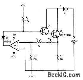
Battery-operate d circuit shown gives adequate stability for strain-gage bridge. Uses four alkaline penlight cells to provide ±3 V for 741 opamp. E1 is chosen to give adequate voltage for intended load at maximum load current. Temperature stability is 0.7 μA/℃ from 0 to 50℃. -R. Tenny, Isolated Current Source, EDN Magazine, April 20, 1973, p 85. (View)
View full Circuit Diagram | Comments | Reading(926)
SQUARE_WAVE_TUNNEL_DIODE
Published:2009/7/16 2:36:00 Author:Jessie
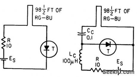
Short-circuited coaxial cable may be connected either in series or in parallel with tunnel diode of basic relaxation oscillator,to get square-wave output with excellent frequency stability over entire bias range.-Wen-Hsiung Ko, Designing Tunnel Diode Oscillators, Electronics, 34:6, p 68-72. (View)
View full Circuit Diagram | Comments | Reading(1123)
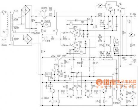
High-precision Constant Voltage And Constant Current DC Power Supply Circuit
Published:2011/7/17 21:32:00 Author:Felicity | Keyword: High-precision, Constant Voltage, Constant Current, DC Power Supply Circuit
View full Circuit Diagram | Comments | Reading(4130)
FLASHING_LED_HV_SUPPLY_CIRCUIT
Published:2009/7/13 4:16:00 Author:May
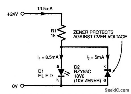
When using FLEDs on a supply voltage higher than the rating of the FLED, precautions should be taken to ensure, that the device never sees a voltage above its maximum rating. (View)
View full Circuit Diagram | Comments | Reading(894)
CHARGING_CURRENT_LIMITER
Published:2009/7/16 4:27:00 Author:Jessie
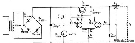
Series regulator transistor is driven by differential amplifier using npn transistors, to control charging of nickel-cadmium battery.-G. H. P. Kohnke, Simple Voltage Regulator Limits Load Current, Electronics, 37:28, p 63. (View)
View full Circuit Diagram | Comments | Reading(1653)
SCR_BATTERY_CHARGING_REGULATOR
Published:2009/7/16 4:25:00 Author:Jessie
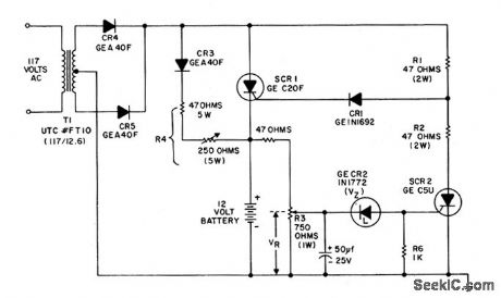
Can charge 12-v battery at up to 6-amp rate.When battery voltage reaches charged level, charging scr shuts off, and trickle charge determined by R4 flows.- Silicon Controlled Rectifier Manual, Third Edition, General Electric Co., 1964, p 109. (View)
View full Circuit Diagram | Comments | Reading(2744)
CHARGER_CONTROL_WITH_REGULATED_D_C_REFERENCE
Published:2009/7/16 4:24:00 Author:Jessie
Eliminates need for separate reference battery. Control fires thyratron to pull in or out and initiate charging cycle when battery voltage drops.-V. Zeluff and J. Markus, Electronics Manual for Radio Engineers, McGraw-Hill, N.Y., 1949, p 545. (View)
View full Circuit Diagram | Comments | Reading(847)
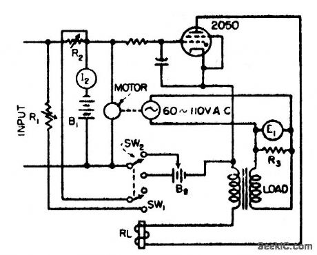
CONSTANT_CURRENT_BATTERY_CHARGER
Published:2009/7/16 4:23:00 Author:Jessie
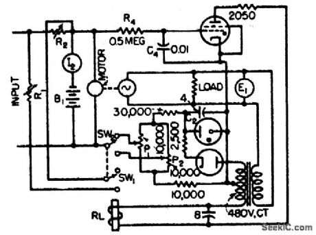
Thyratron-controlled motor drives phasing control rheostat to give fully automatic charging of 50 2-v storage cells at constant role of 2 amp.-J. Markus and V. Zeluff, Handbook of Industrial Electronic Control Circuits, McGraw-Hill, N.Y., 1956, p 150. (View)
View full Circuit Diagram | Comments | Reading(2014)
WELDER_BATIERY_CHARGER
Published:2009/7/16 4:22:00 Author:Jessie
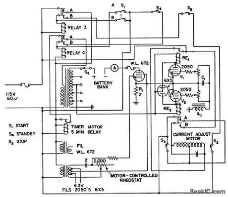
During overnight charging of battery used to maintain equal-amplitude output current pulses for welder, circuit senses whether battery voltage is above or below required value for load current of 1 amp. If low, one-shot timer is actuated, to charge battery for preset interval. Voltage is then measured again, and charging repeated if necessary. If voltage is too high, load remains on until battery voltage drops to point where charger is actuated again.-F. T. Marcellino and A. A. Dargis, Circuit Keeps Voltage Constant for Welder Battery, Electronics, 38:21, p 88. (View)
View full Circuit Diagram | Comments | Reading(2378)
30_W_SEC_SUPPLY_WITH_CHARGER
Published:2009/7/16 4:17:00 Author:Jessie
Charges capacitor to 300 v in 8 to 12 sec through series-line voltage doubler. Battery drain is 750 mo peak and 150 ma idling. Uses transistor collector-base junction in full-wave rectifier circuit to charge nickel-cadmium battery from stepped-down ac voltage across N1 and N2. Converter operates as 120-cps square-wave switch so same transformer may be used for 60-cps charging voltage. Battery provides up to 300 flashes.-H. A. Manoogian, Transistor Photoflash Power Converters, Electronics, 31:35, p 29-31. (View)
View full Circuit Diagram | Comments | Reading(826)
REGULATOR_FOR_PORIABLE_CRO
Published:2009/7/16 4:15:00 Author:Jessie
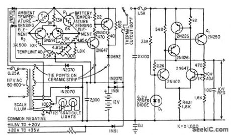
Maintains constant 10-v output from 12-v nickel-cadmium battery, from external d-c voltages up to 35 v, or from 117-v a-c line. Includes battery-charging circuit, in which thermistor R1 senses rise in battery temperature and turns off charger when battery is fully charged.-O. Svehaug and J. R. Kobbe, Battery-Operated Transistor Oscilloscope, Electronics, 33:12, p 80-83. (View)
View full Circuit Diagram | Comments | Reading(941)
THYRATRON_CONTROLS_CHARGER_RECTIFIER
Published:2009/7/16 4:13:00 Author:Jessie
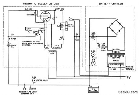
Automatic regular turns charger off when battery voltage exceeds predetermined value, and turns charger on again automatically at any desired lower voltage from 5 to 7.5 v. Line voltage changes do not affect adjustment.-J, Markus and V. Zeluff, Handbook of Industrial Electronic Circuits, McGraw-Hill, N.Y., 1948, p 257. (View)
View full Circuit Diagram | Comments | Reading(948)
NOISE_IMMUNE_BISTABLE
Published:2009/7/16 4:11:00 Author:Jessie

C2 gives immunity to accidental triggering by noise, though with some reduction in switching speed. When C2 is 0.1 mfd, upper frequency limit is 400 cps, and is 100 cps for O.47 mfd. -R. W. Simister, Bistable Multivibrator Immune to Noise, Electronics, 39:6, p 97. (View)
View full Circuit Diagram | Comments | Reading(887)
CHARGER_CONTROL_WITH_REFERENCE_BAT_TERY
Published:2009/7/16 4:11:00 Author:Jessie
Developed to insure constant d-c supply for rotary converters if ship's power supply fails. Control circuit operates SW1 at proper time intervals. B2, in series with B1 with polarity opposing, supplies reference voltage. When storage battery needs charge, gas tube ignites to pull in RL and initiate charging cycle.-V. Zeluff and J. Markus, Electronics Manual for Radio Engineers, McGraw-Hill, N.Y., 1949, p 545. (View)
View full Circuit Diagram | Comments | Reading(875)
QUASI_CONSTANT_CURRENT_BATTERY_CHARGER
Published:2009/7/16 4:10:00 Author:Jessie
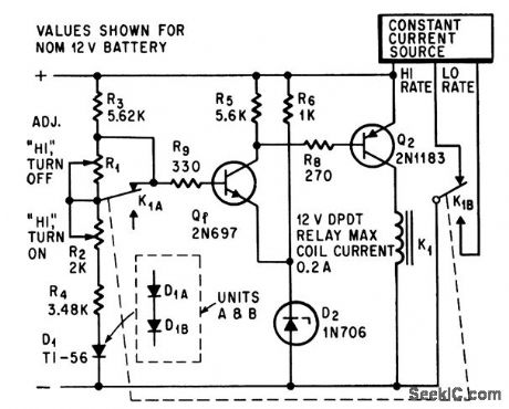
Circuit monitors state of charge of battery while charging at constant high rate, then transfers automatically to constant-current trickle charge when battery is fully charged.-A. Anton, Comparator Controls Battery Charging Rate, Electronics, 37:12, p 72. (View)
View full Circuit Diagram | Comments | Reading(1013)
PREFERRED_SATURATING_BISTABLE
Published:2009/7/16 4:10:00 Author:Jessie
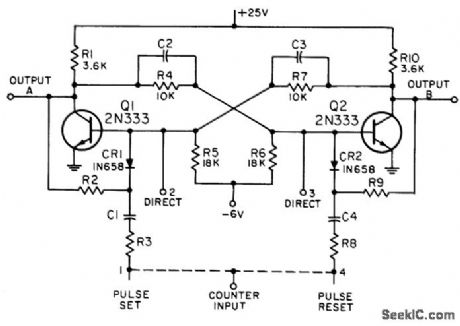
Slow-speed mvbr may be used as counter, shift register, gate, or switch. Provides transitional stages between electromechanical readout and higher-speed nonsaturating bistable counters. Maximum prf is 40 kc, delay time is 2 to 5 microsec, and output levels are both 18 V. 2N333 has been dropped from Preferred List, but 2N335 can be used if operating point is adjusted for its higher beta. -NBS, Handbook Preferred Circuits Navy Aeronautical Electronic Equipment, Vol. II, Semiconductor Device Circuits, PSC 14 (originally PC 250), p 14-2. (View)
View full Circuit Diagram | Comments | Reading(800)
12_V_BATTERY_CHARGER_CONTROL
Published:2009/7/16 4:09:00 Author:Jessie
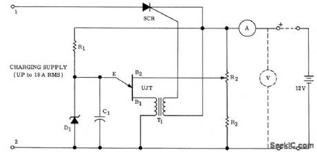
Ujt with R1, R2, R3, and C1 form relaxation oscillator that gets power from battery being charged andserves to trigger scr through T1. When required firing voltage of unijunction, as determined by battery voltage, exceeds break down of zener D1, ujt can no longer oscillate, and charging ceases. R2 controls cutoff point. Charger is protected because scr cannot conduct under conditions of short-circuit, open circuit, or reverse polarity connection to battery. Values are: R13.9K; R2-2.5K; R3-3.3K; C1-0.25 mfd; D1-lN753 zener 6.2 v, 400 mw; SCR-MCR 808-3; UJT-2N2160.-R.Wechsler, A Unique Battery Charger Control Circuit, Motorola Application Note AN-179, Feb. 1966. (View)
View full Circuit Diagram | Comments | Reading(2517)
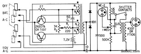
200_W_SEC_SYMMETRICAL_INVERTER
Published:2009/7/16 4:07:00 Author:Jessie
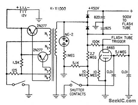
Designed for professional use. Thyratron trigger tube limits shutter contact current to 100 microamp. Converter charges storage capacitors to 90% of full charge in 8 sec. Peak current drain from nickel-cadmium battery during charging is only 5 amp, and idling current is 350 ma. 1,500-cps oscillator uses toroidal saturable-core transformer. 900-v full-wave voltage-doubling circuit has its center grounded, so maximum voltage above or below ground is 450 v.-H. A. Manoogian, Transistor Photoflash Power Converters, Electronics, 31: 35, p 29-31. (View)
View full Circuit Diagram | Comments | Reading(1090)
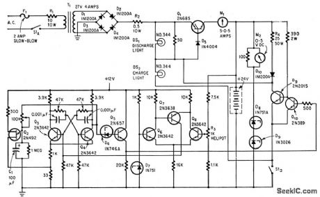
195_V_FROM_27_V_BATTERY
Published:2009/7/13 3:43:00 Author:May
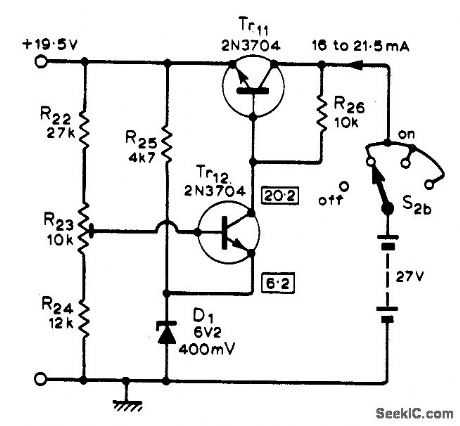
Used to provide precise voltage levels required by portable trigger unit designed to fire up to five different flash units at equal intervals that may range from 11 ms to 11 s. Article gives all circuits.-R. Lewis, Multi-Flash Trigger Unit, Wireless World, Nov.1973, p 529-532.
(View)
View full Circuit Diagram | Comments | Reading(1055)
LOW_POWER_ANTENNA_TUNER_AND_SWR_METER
Published:2009/7/13 3:28:00 Author:May
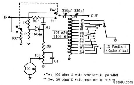
The SWR meter is a variation of a resistive bridge. This circuit has the advantage of providing high sensitivity at low power inputs. Its disadvantage is that the maximum power that can be applied to the circuit is limited by the power dissipation of the 50-Ω bridge resistors because 75 percent of the transmit power is absorbed by these resistors under perfectly matched conditions. In this circuit, a DPDT switch adds in a 100-Ω resistor only for SWR readings, allowing the circuit to provide a reasonable SWR for your transmitter even during severe tune-up conditions. Additionally, you have minimum insertion loss in the FORWARD position because the l-kΩ bridge resistors permit you to always indicate forward relative power and calibrate the full-scale reading for SWR measurements. The antenna tuner itself is a standard T-type tuner utilizing a pair of 335-pF miniature transistor radio variable capacitors and a toroidal inductor, tapped as shown in the figure. To actually make the taps, simply wind the toroid with 40 turns of #24 wire, and then scrape the outer surface of each appropriate tum with a hobby knife to clean off the enamel insulation. Then tin each wire turn, and tack-solder tap wires to them. (View)
View full Circuit Diagram | Comments | Reading(3564)
| Pages:76/291 At 206162636465666768697071727374757677787980Under 20 |
Circuit Categories
power supply circuit
Amplifier Circuit
Basic Circuit
LED and Light Circuit
Sensor Circuit
Signal Processing
Electrical Equipment Circuit
Control Circuit
Remote Control Circuit
A/D-D/A Converter Circuit
Audio Circuit
Measuring and Test Circuit
Communication Circuit
Computer-Related Circuit
555 Circuit
Automotive Circuit
Repairing Circuit