
power supply circuit
Index 68
PHILIPS LCD DC/DC Convertor Circuit
Published:2011/7/14 0:19:00 Author:Joyce | Keyword: PHILIPS , LCD, DC/DC , Convertor
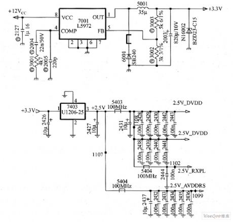
PHILIPS LCD DC/DC convertor circuit is as shown . (View)
View full Circuit Diagram | Comments | Reading(1004)
Sound excitation switch circuit
Published:2011/7/18 6:36:00 Author:Christina | Keyword: Sound, excitation, switch circuit
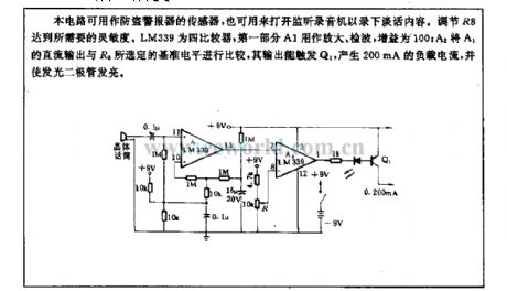
This circuit can be used as the sensor of the anti-theft alarm, and it can be used to open the monitor recorder to record the conversation. You can get the required sensitivity by adjusting R8. LM229 is the quad comparator, the first part A1 can be used in the amplification and the wave detection, the gain is 100; A2 compares the DC output of A1 with the selected reference level of R8, the output can trigger the Q1 to produce the 200mA load current and turns on the light-emitting diode.
(View)
View full Circuit Diagram | Comments | Reading(877)
High input voltage voltage-stabilization circuit
Published:2011/7/13 6:42:00 Author:Christina | Keyword: High input voltage, voltage-stabilization
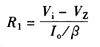
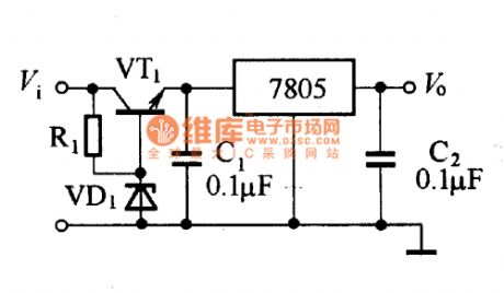
The maximum input voltage-stabilization circuit can be used in the condition of the input voltage, itis higher than the rated voltage of the voltage stabilizer, the high partial pressure power transistor is connected in the input circuit. The resistance value of R1 can be comfirmed by this formula:
In this formula:
Vi--input voltage;VZ--voltage stabilization value of the voltage stabilization diode;Io--the maximum output current of the integrated voltage stabilizer;β--current amplification coefficient of the semiconductor transistor.
(View)
View full Circuit Diagram | Comments | Reading(1595)
Simple And Practical Voice-Controlled Electronic Doorbell Circuit
Published:2011/8/4 0:35:00 Author:Robert | Keyword: Simple, Practical, Voice-Controlled, Electronic, Doorbell
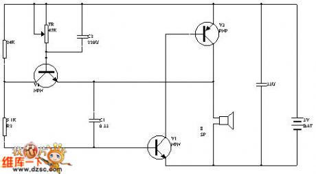
If using this circuit as doorbell circuit, it needn't to install the button switch on the door. The visitors could just knock the door, and the doorbell would sound. The circuit is shown in the picture.
The greatest feature of the circuit is using the loudspeaker as vibration input and also the doorbell sound output.
The transistor V2, potentiometer KP and capacitor C2 make up the control circuit. The V1, V3, R2, C1 make up a complementary oscillator. When the switch S is closed and connected to the power, the power would charge the C2 through the C2, V2's BE junction and loudspeaker BL. The larger peak charging current make V2 saturated and conducted, which clamps the V3's collector polar's voltage level. After the C2's charging, the power would supply the base polar current for V2 through KP, thus it would maintain V2's critical saturation status and make the oscillator not work. (View)
View full Circuit Diagram | Comments | Reading(2529)
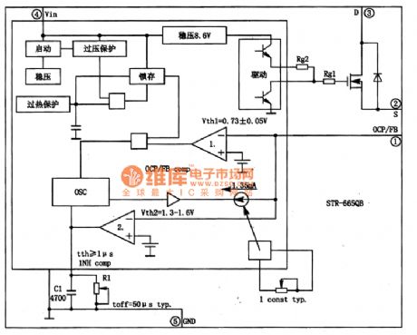
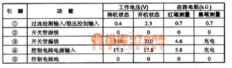
STR-6658B power supply thick film hybrid integrated circuit
Published:2011/8/9 19:57:00 Author:Sophia | Keyword: Power supply thick film hybrid integrated
(View)
View full Circuit Diagram | Comments | Reading(1798)
STR-F6454R Switching power supply thick film integrated circuit diagram
Published:2011/8/8 0:23:00 Author:Sophia | Keyword: Switching power supply, thick film integrated circuit
(View)
View full Circuit Diagram | Comments | Reading(1490)
NEC mobile charger circuit diagram
Published:2011/8/4 21:10:00 Author:Sophia | Keyword: NEC mobile charger
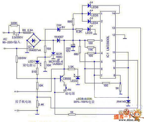
NEC mobile phone charger circuit is shown as below When C1 selected 2.2? F/250V AC step-down capacitor, the output current is about 130mA. Mobile phone battery charging time can be easily selected according to the capacity, so the battery will not be damaged. Specific discharge functions can extend nickel-cadmium battery life with the memory effect. Charging power is indicated by the four high-brightness light-emitting diode level indication, which is very intuitive. In the charging circuit, the AC depressurization capacitor and discharge control tube C8550 are delicate components. When we need to maintain these two components, we can use comprehensive similar component to replace them. (View)
View full Circuit Diagram | Comments | Reading(3906)
The constant voltage/constant current power resources circuit formed by CW117/CW217/CW317
Published:2011/8/10 19:05:00 Author:leo | Keyword: Constant voltage, constant current, power resources
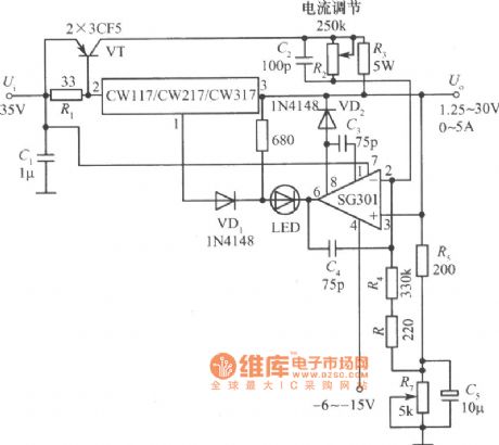
As the picture shows, it is a constant voltage/constant current power supply circuit. It is made up of extend current part, constant voltage part and constant current part. Two power transistors are parallel connected to form the extending current tube. And R3 is the current limited resistance while R2 is current electric level adjusting device. R is the voltage electric level adjusting device. This power resources can offer the voltage of 1.25 V to 30 V with the current of 0 to 5A. (View)
View full Circuit Diagram | Comments | Reading(3268)
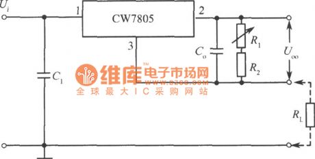
The constant current power resources circuit with adjustable output current formed by CW7805
Published:2011/8/10 19:05:00 Author:leo | Keyword: Constant current, power resources, adjustable output current
View full Circuit Diagram | Comments | Reading(2750)
The absolute sine wave inverted power supply circuit made by MCU
Published:2011/8/10 19:06:00 Author:leo | Keyword: Sine wave, MCU, inverted power supply
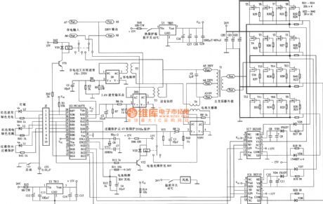
Absolute sine wave inverted power supply circuit made by MCU (View)
View full Circuit Diagram | Comments | Reading(1695)
ZDD-12-160 full auto multi-functional inverted power supply circuit
Published:2011/8/10 19:06:00 Author:leo | Keyword: Full auto, multi-function, inverted power supply
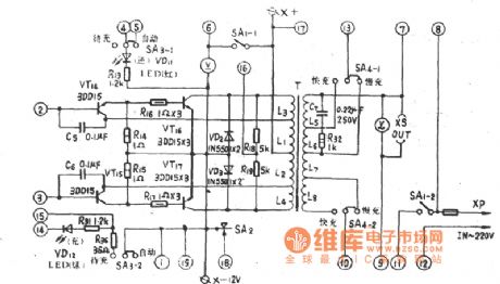
ZDD-12-160 full auto and multi-functional inverted power supply pre-circuit
ZDD-12-160 full auto and multi-functional inverted power supply final stereo circuit
(View)
View full Circuit Diagram | Comments | Reading(903)
The low power constant voltage power resources circuit formed by HIP5600(NO transformer)
Published:2011/8/10 19:07:00 Author:leo | Keyword: Low power, constant voltage, power resources, no transformer

The constant voltage power resources circuit has many unique features:1.DC work voltage can reach 400V2.AC work voltage can reach 280 V3.It can be connected to two outer resistances. Its DC input voltage is 1.2 V and can be adjusted from VIN to 50 V. The input current can be adjusted from 1 mA to 30 mA.4. It has its own cooler and does not need outer protecting circuit.
(View)
View full Circuit Diagram | Comments | Reading(1423)
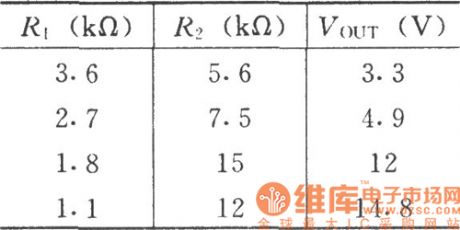
The no transformer constant voltage power resources circuit formed by LR6
Published:2011/8/10 19:08:00 Author:leo | Keyword: No transformer, constant voltage, power resources
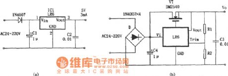
As the picture shows, these are two different constant voltage power resources formed by LR6. LR6 is a kind of high input voltage and low output voltage linear AVR without transformer. It has many kinds of packages, such as TO-92,TO-220,TO-243,DIP8 and so on. Its output voltage is 10 V and output current is 3 mA. Picture (a) is power resources circuit and picture (b) is the extending current circuit. R1+R2=250k (changing the value of R1 and R2 can cause the change of the voltage from 10 V to 12 V).
(View)
View full Circuit Diagram | Comments | Reading(1742)
The projectile lamp voltage stabilization circuit
Published:2011/7/29 4:39:00 Author:Borg | Keyword: projectile lamp, voltage stabilization circuit
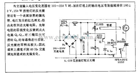
When the AC input voltage changes within 105~250v, the effective voltage on the bulb keeps at 100±2V. Behind the mirror of the 150W projectile lamp, there is a black light leakage tube. The red light emitted by the lamp reaches the LDR through the tube. The resistance change of the LDR is fed back to the igniting circuit Q1-Q2, which controls the conducting angle of the SCR Q3. The coverage of the mirror is big, so it can feel the light change caused by the 60Hz DC light regulation.
(View)
View full Circuit Diagram | Comments | Reading(777)
The 500A power switch control circuit
Published:2011/7/29 4:37:00 Author:Borg | Keyword: power switch, control circuit
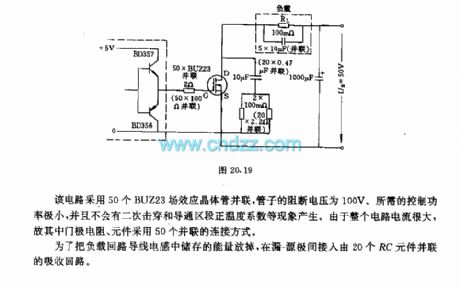
The circuit is fixed with 50 parallel BUZ23 FET transistors, the blocking voltage of the tube is 100V. The needed control power is very low, and there aren't any phenomenon of twice breakdown or conducting area forward temperature coefficient. As the current of the whole current is very high, so the 50 gate resistors and elements are connected in parallel method. To release the energy in the wire inductors of the loading circuit, an attraction circuit composed of 20 parallel RC elements is connected between the leakage-source pole. (View)
View full Circuit Diagram | Comments | Reading(972)
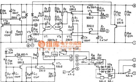
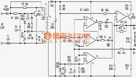
Charger for Motor Vehicle Storage Battery (the 3rd)
Published:2011/7/29 4:21:00 Author:Felicity | Keyword: Charger, Motor Vehicle, Storage Battery
Work of the circuit
The circuit consists of power circuit, pulse oscillator and charging controlling circuit. (It is showed in picture 7-148.)
Power circuit consists of power transformer T, the normally closed contacts K2 relay, normally open contacts of relay Kl, bridge rectifier, URl, UR2, voltage regulator diode VS, capacitor CO, Cl, resistors RO, Rl, fuse FUl, indicating light HL and ammeter PA.
Pulse oscillator consists of time-base integrated circuit IC, potentiometer RPl and related peripheral components.
Charging controlling circuit consists of thyristor VT, relay K2, potentiometer RP2 and peripheral components.
220V AC voltage is adjusted and produces +12V voltage. It works as the working voltage of the pulse oscillator. When the OSC is working, the pulse of IC controls the working condition of relay K1. When the pulse OSC outputs low electrical level, GB is charged. At the same time, the light HL is lightened. When the pulse OSC outputs high electrical level, GB is not charged. And the light HL stops shining. When GB is not fully charged, the indicating light VL does not shine. But when GB is fully charged, VL shines to show that charging is done. (View)
View full Circuit Diagram | Comments | Reading(824)
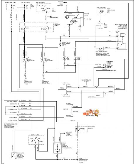
Mazda 95TAURUS (no power windows) gate lock circuit
Published:2011/8/4 8:56:00 Author:nelly | Keyword: power windows, gate lock
View full Circuit Diagram | Comments | Reading(755)
Nokia 8210 mobile phone travel charger circuit diagram
Published:2011/8/4 21:20:00 Author:Rebekka | Keyword: travel charger, Nokia mobile phone
The Nokia 8210 mobile phone travel charger produced by Shanghai has been marked on the shell: input AC220V/50Hz(≤30mA),output 4.2V(≤200mA). When people use it to charge the 3.6V rechargeable lithium battery, the red light will be turned off and green light turned on when the it is charged to 3.98V. the whole charging time is about 4 hours. The op amp in the circuit is used as the comparator.
(View)
View full Circuit Diagram | Comments | Reading(5745)
CF1458 series dual power supply general-purpose dual op amp circuit diagram
Published:2011/8/4 20:57:00 Author:Rebekka | Keyword: dual power supply, general-purpose , dual op amp
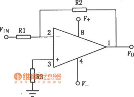
CF1458 series op amps are high-performance dual op amps. Its electrical properties and /-A747 are the same, buttheir pin arrangement is different. The series features are: No external frequency compensation components, short circuit protection and it has the ability to offset voltage to zero. There is a wide differential mode and common mode input voltage range, low power consumption, the use will not becongested. Substitution models of similar or directly are CF1558MT, CF1458CT, CF1558NMT, CF1458NCT, CF1558SMT, CF1458SCT, CF1558MD, CFl458CD, CFl558MJ, CFl458cJ, CFl458CP, CFl558NMD, Fl458NCD, CFl558SMJ, CFl458SCJ, CFl458SCP, CFl558SMD and so on. (View)
View full Circuit Diagram | Comments | Reading(1462)
Multiplexed output digital camera power supply circuit composed of MAX1802
Published:2011/5/10 1:47:00 Author:Rebekka | Keyword: Multiplexed output digital camera , power supply
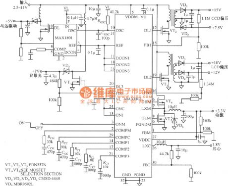
Composed of MAX1802 multiple output digital camera power supply circuit diagram is shown as below. MAX1802 Chip has 2 buck converters and 3 boost converters. Input voltage 2.5~11V, continuously adjustable output voltage 2.7~5.5V. The lowest output voltage can be ajdusted to 1.25V. The working rate of MAX1802 can be adjusted to 1MHz and conversion efficiency can up to 94%.
(View)
View full Circuit Diagram | Comments | Reading(2345)
| Pages:68/291 At 206162636465666768697071727374757677787980Under 20 |
Circuit Categories
power supply circuit
Amplifier Circuit
Basic Circuit
LED and Light Circuit
Sensor Circuit
Signal Processing
Electrical Equipment Circuit
Control Circuit
Remote Control Circuit
A/D-D/A Converter Circuit
Audio Circuit
Measuring and Test Circuit
Communication Circuit
Computer-Related Circuit
555 Circuit
Automotive Circuit
Repairing Circuit