
power supply circuit
Index 97
12_V_AT_10_A
Published:2009/7/17 1:55:00 Author:Jessie
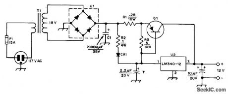
Permits AC operation of 12-V FM transceiver. Article tells how to rewind 12-V TV power transformer rated above 120 W with No.12 enamel to get required 18-V secondary. If original winding has 2 turns per volt, new secondary will need 36 turns. Q1 is HEP233, HEP237, or similar transistor rated 10 A or higher, with heatsink, U1 is 25-A 100-PlV bridge rectifier, and U2 is National LM340K-12 regulator. CR1 can be any rectifier rated at least 3 A at 35 V. - L. McCoy, The Ugly Duckling, QST, Nov.1976, p 29-31. (View)
View full Circuit Diagram | Comments | Reading(1127)
2000_V_LOW_CURRENT_POWER_SUPPLY
Published:2009/7/11 5:05:00 Author:May
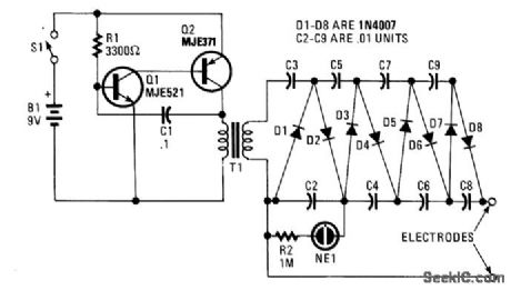
In this circuit Q1, Q2, R1, and C1 form a multivibrator. The square wave that results from the oscillation of this circuit (20 to 30 Vpp) is stepped up by T1 (an audio transformer of the type used in radios or small TVs). An 8- to 1,200-Ω impedance ratio equates to a turn ratio of 12:1. The ac from the secondary of T1 is applied to the multiplier circuit (D1 to D8 and C2 to C9). NE1/R2 are used as an operating indicator. The circuit will supply about 2,000 V. C2 to C9 should have a 400-V or higher voltage rating. (View)
View full Circuit Diagram | Comments | Reading(827)
LASER_POWER_SUPPLY
Published:2009/7/11 5:00:00 Author:May
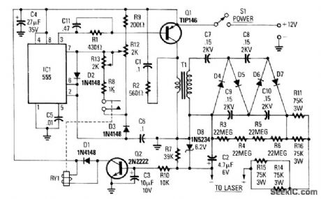
IC1 is a 555 timer running at about 16 kHz. This IC drives Q1, a TIP146, which produces a 12-V square wave across T1 primary. This produces between 800 and 2,000 V across the secondary, which is doubled to 3 to 5 kV. When the load (laser) on the power supply increases, current Q2 is turned on, which energizes RY1. This changes the duty cycle of the 555 timer. To adjust this supply, set R12 and R13 at the center. Adjust R12 until the laser tube triggers, and make sure that the relay pulls in. If the relay chatters, adjust R12. If the full-clockwise adjustment of R12 fails to ignite the tube, adjust R13. (View)
View full Circuit Diagram | Comments | Reading(0)
10_000_Vdc_SUPPLY
Published:2009/7/11 4:45:00 Author:May
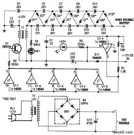
A CMOS oscillator (U1A) drives. U1B through U1F, which drives Q1, which generates a 12-Vpp square wave across the primary of T1. This square wave is applied to a rectifier-multiplier circuit consisting of D1 through D10 (each is two 1N4007 diodes in series) and C3 through C12. About 10 kV is available. (View)
View full Circuit Diagram | Comments | Reading(832)
VIBRATION_DETECTOR
Published:2009/7/17 3:01:00 Author:Jessie
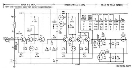
Low-frequency boost compensates for characteristics of velocity-type vibration detector for turbines. Detector voltage is proportional to both displacement and frequency, so integrating action by capacitance feedback around high-gain amplifier stage makes output proportional to displacement only.-H. A. Harriman and W. M.Trenholm, Vibration Measurements with Peak-Reading Circuit, Electronics, 35:20,p 57-59. (View)
View full Circuit Diagram | Comments | Reading(2010)
IMPROVED_REGENERATIVE_SW_RECEIVER
Published:2009/7/17 3:00:00 Author:Jessie
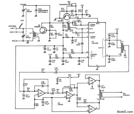
The figure shows the schematic of the circuit. A number of unique features give this design its trouble-free performance. The tendency for regenerative receivers to radiate oscillator-frequency signals is eliminated here by placing a transistor buffer Q1 between the antenna preselector circuit L1-C1a and the regenerative oscillator-tuned circuit L2-C1b. This buffer also nearly eliminates hand-capacitance effects. This design is also unique in that it uses an IC for the regenerative detector. U1, an LM1496 double-balanced mixer, is used here in a somewhat unorthodox manner. The differential SIGNAL INPUT amplifier transistors internal to the IC are used as a Hartley oscillator in conjunction with L2 and C1b. The regenerative feedback for this oscillator is supplied by the output of the GAIN and ADJUST pins of the LM1496. Some of the oscillator output is coupled to one of the CARRIER IN-PUT pins via C9, which allows the mixer section of U1 to act as an asynchronous detector, greatly improving the RE detection sensitivity over that of other regenerative circuits. The regeneration level is controlled by the voltage level applied to the BIAS pin of U1. The circuit containing R12 and transistor Q2 is used as a variable-voltage source, providing the regeneration level immunity from supply-voltage ripple. This bias level controls the quiescent current level through the SIGNAL IN-PUT amplifier transistors, which, in turn, determines the emitter output impedance of these transistors, controlling the amount of power delivered to the feedback winding of L2. This results in very smooth and predictable regeneration control. The outputs of U1 are coupled through audio trans-former T1 into the first section of U2, an LM324 op amp. Volume control is achieved though U2d and variable resistor R18. Using a push-pull audio output stage, as is done here, also reduces susceptibility to audio oscillation. Although the use of switched or plug-in coils could have allowed multiband reception, in the interest of simplicity, this was not done. However, the values of L1 and L2 allow coverage of 5 to 15 MHz, where much of the shortwave action occurs. (View)
View full Circuit Diagram | Comments | Reading(5339)
Low_drift_integrator_with_low_leakage_guarded_reset
Published:2009/7/17 3:00:00 Author:Jessie

Low-drift integrator with low-leakage-guarded reset (courtesy Analog Devices, Inc.). (View)
View full Circuit Diagram | Comments | Reading(848)
SWITCH_MODE_VOLTAGE_REGULATOR
Published:2009/7/17 2:59:00 Author:Jessie
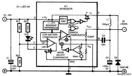
Switch-mode power supplies offer the benefit of a much greater efficiency than obtainable with a tradi-tional power supply. The switch-mode regulator presented here has an efficiency of around 85%.
An input voltage of 12 to 16 Vdc is convened into a direct voltage of exactly 5 V. The use of a MAX638CPA enables the design and construction of the regulator to be kept fairly simple: only nine additional components are needed to complete the circuit.
Resistors R1 and R2 are used to indicate when the battery voltage becomes low: as soon as the voltage on pin 3 becomes lower than 1.3 V, D1 lights. With values as shown for the potential divider, this corresponds to the supply voltage getting lower than about 6.5 V. The output of the IC is shunted by a simple LC filter formed by L1, C3 and D2.
The oscillator on board the IC generates a clock frequency of around 65 kHz and drives the output transistor via two NOR gates. The built-in error detector, the battery low indicator or the voltage comparator can block the clock frequency, which causes the transistor to switch off.
The IC compares the output voltage of 5 V with a built-in reference (FET). Depending on the load, the FET will be switched on for longer or shorter periods. The maximum current through the FET is 375 mA, which corresponds with a maximum output current of 80 mA. (View)
View full Circuit Diagram | Comments | Reading(1120)
RADAR_SPEED_METER
Published:2009/7/17 2:59:00 Author:Jessie
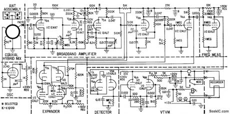
Translates doppler or difference frequency between transmitted and received frequencies into mph and displays on meter or records on strip chart. Operates at 2,455 Mc and is accurate within 2 mph up to 100 mph.-J. Barker, Radar Metet Helps Enforce Traffic Laws, Electronics, 32:10, p 48-49. (View)
View full Circuit Diagram | Comments | Reading(913)
FET_PINCHOFF_VOLTAGE
Published:2009/7/17 2:58:00 Author:Jessie
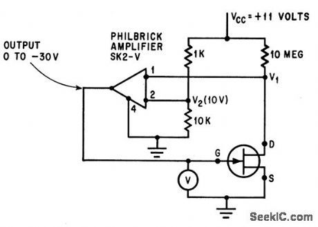
Measures gate-source voltage while drain current is below 0.1 microamp, to give value that matches pinchoff voltage of let.-B. R. Smith and I. C. Chase, Matching Cote Potential to FET Pinchoff Voltage, Electronics, 38:16, p 81. (View)
View full Circuit Diagram | Comments | Reading(759)
Operational_integrator
Published:2009/7/17 2:57:00 Author:Jessie
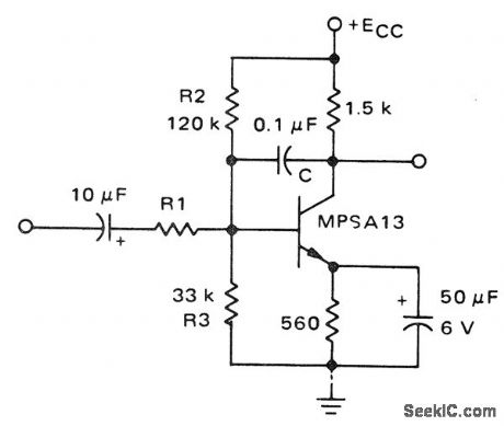
Operational integrator. Two cascaded 2N3904s can replace the MPSA 13 (courtesy Motorola Semiconductor Products Inc.). (View)
View full Circuit Diagram | Comments | Reading(939)
VAVUM_TUBE_SW_RECEIVER
Published:2009/7/17 2:57:00 Author:Jessie
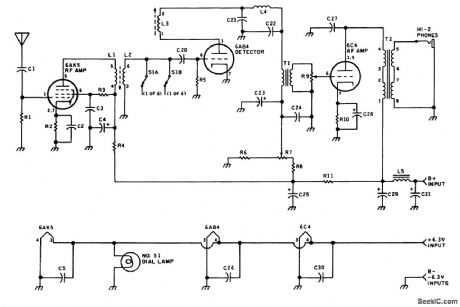
This vacuum-tube receiver covers from 9.4 to 22 MHz and is of interest to those hobbyists who wish to experiment with vacuum-tube circuitry. (View)
View full Circuit Diagram | Comments | Reading(1700)
PROTON_PRECESSION_MAGNETOMETER
Published:2009/7/17 2:57:00 Author:Jessie
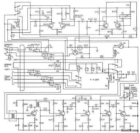
Used in Vanguard III satellite for magnetic field measurements at altitudes of 510 to 3,750 km.-D. Mansir, Magnetic Measurements in Space, Electronics, 33:32, p 47-51. (View)
View full Circuit Diagram | Comments | Reading(999)
MULTICHANNEL_MO_N_ITOR
Published:2009/7/17 2:56:00 Author:Jessie
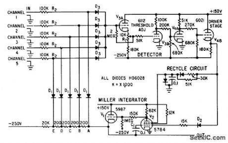
Automatically detects single signal coming from large number of separate sources and identifies source, as required in doppler radar sets that must search bank of sharp filters placed side by side, to detect target, while antenna scans field of search. Positive signal reaching detector is amplified to drive Miller integrator V1-V2. As V1 goes negative, it disconnects one channel at a time (by driving its disconnecting diode D1 below 0 V) until live channel is reached. Detector output is then cut off, and C1 stores level at which disconnect occurred.-R. Kronlage, Monitoring Multiple Inputs Simultaneously, Electronics, 32:35, p 50-51. (View)
View full Circuit Diagram | Comments | Reading(677)
RECEIVER_INCREMENTAL_TUNING_CIRCUIT
Published:2009/7/17 2:56:00 Author:Jessie
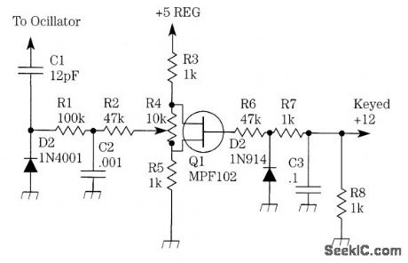


D1 acts as a varactor diode coupled to the transceiver or receiver LO tuning circuit. On receive, Q1, the MPF102, is cut off and the varactor voltage is controlled by the 10-kΩ pot. On transmit, Q1 conducts; this effectively shorts the 10-kΩ pot, placing a fixed voltage on the varactor diode. (View)
View full Circuit Diagram | Comments | Reading(1005)
CAPACITANCE_METER
Published:2009/7/17 2:55:00 Author:Jessie
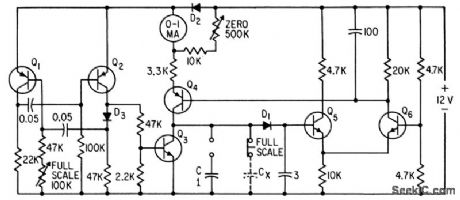
Milliammeter indicates capacitance values over any desired range on linear scale having zero at right.-W. Mosinski, Capacitance Meter has Linear Scale, Electronics, 35:12, p 64. (View)
View full Circuit Diagram | Comments | Reading(4431)
Latching_DPDT_switch
Published:2009/7/17 2:48:00 Author:Jessie
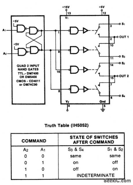
Latching DPDT switch.The A1 and A2 inputs are normally low A high input to A2 turns S1 and S2 on,A highto A1 turns S3 and S4 on,This feature is desirable with limit detectors,peak detectors or mechanical closures(courtesy Intersil,Inc.). (View)
View full Circuit Diagram | Comments | Reading(1060)
NE602_OUTPUT_CONFIGURATIONS
Published:2009/7/17 2:48:00 Author:Jessie
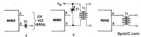
Here are (a) a simplest single-ended approach without impedance matching, (b) a single-ended approach for a tuned LC circuit load, and (c) a balanced approach for better suppression of input and LO signals. (View)
View full Circuit Diagram | Comments | Reading(760)
30_MHz_IF_PREAMP
Published:2009/7/17 2:47:00 Author:Jessie
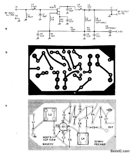
This preamp for 30 MHz is useful for IF applications used in microwave work, etc. A 40673 MOSFET is used and typically the gain at 30 MHz will be 20 to 25 dB. (View)
View full Circuit Diagram | Comments | Reading(876)
SAWTOOTH_CLIPPER
Published:2009/7/17 2:47:00 Author:Jessie
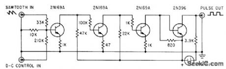
High-gain amplifier converts sawtooth input to rectangular out.put pulse whose width is proportional to portion of sawtooth amplitude that is above threshold level.-B. E. Mathews and F. R. Sias, Jr., Testing Space Craft with Induction Heaters, Electronics, 35:34, p 38-41. (View)
View full Circuit Diagram | Comments | Reading(763)
| Pages:97/291 At 2081828384858687888990919293949596979899100Under 20 |
Circuit Categories
power supply circuit
Amplifier Circuit
Basic Circuit
LED and Light Circuit
Sensor Circuit
Signal Processing
Electrical Equipment Circuit
Control Circuit
Remote Control Circuit
A/D-D/A Converter Circuit
Audio Circuit
Measuring and Test Circuit
Communication Circuit
Computer-Related Circuit
555 Circuit
Automotive Circuit
Repairing Circuit