
power supply circuit
Index 113
JFET_chopper_with_extended_range_of_±10_volts
Published:2009/7/19 23:07:00 Author:Jessie
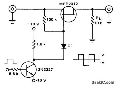
JFET chopper with extended range of ±10 volts (courtesy Motorola Semiconductor Products Inc.). (View)
View full Circuit Diagram | Comments | Reading(901)
Power_down_to_SBC_80_20_interface
Published:2009/7/19 22:23:00 Author:Jessie
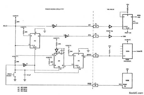
Power down to SBC 80/20 interface. The SBC 80/20 is a single board computer containing an 8259 programmable interrupt controller (courtesy Intel Corporation). (View)
View full Circuit Diagram | Comments | Reading(1152)
TUNNEL_DIODE_COINCIDENCE
Published:2009/7/19 22:21:00 Author:Jessie

Used in liquid scintillation counter for carbon-14 and other radioactive solutions delivers output pulse to stretcher ampliflier only for coinciding pulses from two photomultiplier inputs.-G. J. Sprokel, A Liquid Scintillation Counter Using Anticoincidence Shielding, IBM Journal of Research and Development, 7:2, p 135-145.
(View)
View full Circuit Diagram | Comments | Reading(704)
SClNTILLATION_COUNTER_ANTI_COINClDENCE
Published:2009/7/19 22:13:00 Author:Jessie

Produces an output from a trigger at in.put 1 only if input 2 is not triggered at that time. Used in liquid scintillation counter where expected count mtes are low.-G. J Sprokel, A Liquid Scintillation Counter Using Anticoincidence Shielding, IBM Journal of Research and Development, 7:2, p 135-145. (View)
View full Circuit Diagram | Comments | Reading(1100)
RADIOLOGICAL_VACUUM_GAGE
Published:2009/7/19 21:52:00 Author:Jessie
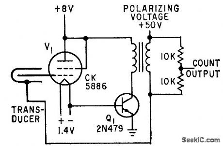
Permils measuring extremely low pressures in laboratory equipment and in high-althude research. Provides digital output that can be used for storage for telemetry. Transformer is audio type with Iarge step-up ratio. Polarizing voltage supplies less than 1 microamp. Transducer is small cylindrical tube lined with radioactive foil.-G. F. Vanderschmidt, Using lsotopes to Measure tow Pressures, Electron-ics, 32:25, p 60-61. (View)
View full Circuit Diagram | Comments | Reading(893)
_15_5AND__15V
Published:2009/7/19 21:52:00 Author:Jessie


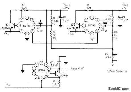
Single potentiometer R5 serves for adjusting all three regulated output voltages simultaneously Accuracy of adjustment is within 2%.-R.C Dobkin. One Adjustment Controls Many Regulators .EDN Magazine,Nov,1,1970,p33-35 (View)
View full Circuit Diagram | Comments | Reading(729)
Tachometer_with_set_point
Published:2009/7/19 21:51:00 Author:Jessie
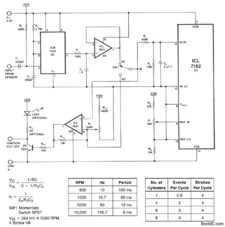
This circuit shows an ICLT182 bargraph converter that is connected to form a tachometer with set point. The connections between the ICL7182 and bargraph are shown in Fig. 12-14. Harris Semiconductor$ Data Acquisition 1991 p 2 144 (View)
View full Circuit Diagram | Comments | Reading(0)
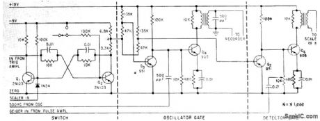
SURVEY_METER_HAS_PULSED_AND_CURRENT_MODES
Published:2009/7/19 21:51:00 Author:Jessie
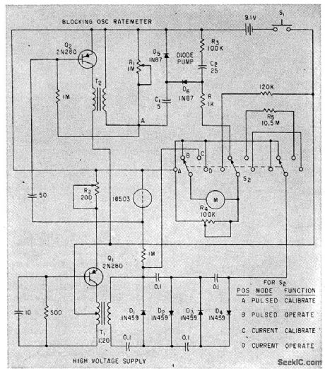
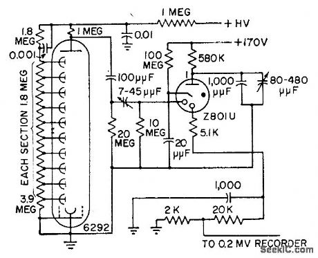
High-voltage source for G-M counter uses 10-kc blocking oscillator and Cockcroft-Walton multiplier, to give 550 v stabilized by zener region of D1. Range for pulsed operation is 0.5 to 50 milliroentgen per hour. For current mode, same 18503 G-M tube is used, and current in range of 50 milliroentgen to 5 roentgen per hour is logarithmic function of radiation intensity.-R. W. Lehnert and J. M. McKenzie, Radiation Survey Meter, Electronics, 35:8, p 50. (View)
View full Circuit Diagram | Comments | Reading(1002)
Bargraph_display_of_quad_load_cell_values
Published:2009/7/19 21:50:00 Author:Jessie
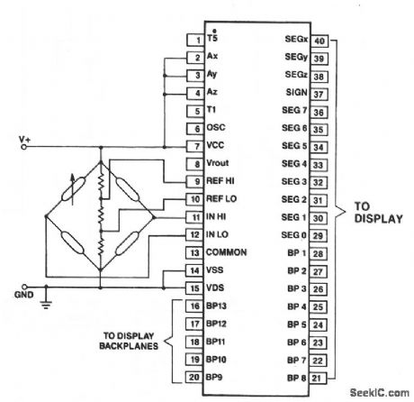
This shows an ICL7182 bargraph converter connected to measure ratiometric values of quad load cells, and to display the results on a bargraph. The resistor values within the load-cell bridge are determined by the desired sensitivity.Harris Semiconductors, Data Acquisition 1991 p. 2-143 (View)
View full Circuit Diagram | Comments | Reading(3415)
POWER_TO_VOLTAGE
Published:2009/7/10 3:36:00 Author:May
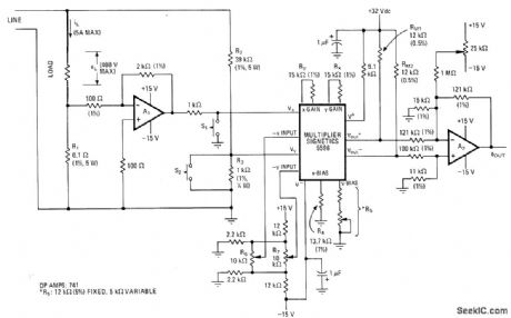
Two Oρamρs and inexpensiveIC multiplier provide output voltage directly ρroρortional to instantaneous power through load. Frequency response extends from DC to several kilohertz.Maximum load powerfor linearity is 2 kVA, with maximums of 400 V and 5 A for load voltage and current. Output voltage can vary from -10 V to +10 V depending on instantaneous polarities and magnitudes of load voltage and current. R1 determines current range, and R2 determines voltage range.-D. DeKold, Integrated Multiplier Simplifies Wattmoter Design, Electronics, Sept. 27, 1973, p 106-107; reprinted in Circuits for Electronics Engineers, Electronics, 1977, p 175-176. (View)
View full Circuit Diagram | Comments | Reading(793)
_10V_TO__05V
Published:2009/7/19 22:26:00 Author:Jessie
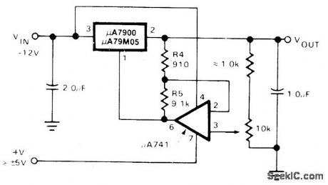
Regulator in μA7900 series is used with 741 opamp to provide adjustable output voltage. Differential between input and output is 2V.- Signetics Analog Data Manual, SignetIcs, Sunnyvale, CA, 1977, p 670. (View)
View full Circuit Diagram | Comments | Reading(581)
2_KC_COLD_CATHODE_COUNT_RATE_CIRCUIT
Published:2009/7/19 22:26:00 Author:Jessie
Uses triode having separate cold-cathode diode that produces glow discharge to eliminate trigger-cathode gap of triode section. This eliminates photosensitivity shown by most cold-cathode devices. Maximum operating speed is 2,000 counts per second.-M. H.Goosey, Designing Cold-Cathode Tube Circuits, Electronics, 31:3, p 101-108. (View)
View full Circuit Diagram | Comments | Reading(727)
POST_DETECTION_DIVERSITY_COMBINER
Published:2009/7/19 22:25:00 Author:Jessie
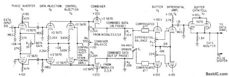
Can handle any IRIG modulating signal and feed any telemetry receiver having external agc output. Will combine two, three, or four channels.-W. Casson and R. C. Robinson, Versatile Diversity Combiner Handles Most Missile-Range Signals, Electronics, 35:44, p 40-43.
(View)
View full Circuit Diagram | Comments | Reading(1326)
5_24V
Published:2009/7/19 22:25:00 Author:Jessie
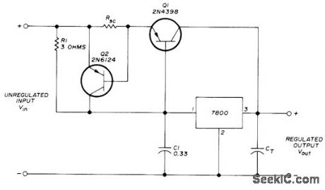
Choice of regulator in 7800 series determines value of output voltage that is maintained within 0.05% of its actual value. Choose regulator for voltage desired. Unregulated input Vin must be at least 2 V higher than regulator rating. Transient suppression capacitor CT is typically 10 to 50 μF. Output current is increased above IC rating by using PNP series-pass transistor Q1 which has maximum collector current of 30 A. Protection circuit Q2 pre-vents burnout of power transistor. Choose RSC for limiting current value to desired value.-J.E. Trulove, Three-Terminal Voltage-Regulator ICs, Ham Radio, Dec. 1973, p 26-30. (View)
View full Circuit Diagram | Comments | Reading(944)
RADIOACTIVE_FUEL_FLOW_GAGE
Published:2009/7/19 22:23:00 Author:Jessie
Used in recording flow rate of let fuel containing radioactive tracer.-J. D. Keys and G. E. Alexander, Radioactive Tracers Find Jet Fuel Flow Roles, Electronics, 33:8, 58-59. (View)
View full Circuit Diagram | Comments | Reading(650)
Transistor_based_thermometer
Published:2009/7/19 22:23:00 Author:Jessie
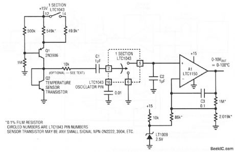
This circuit provides a 0- to 10-V output, corresponding to a 0 to 100℃ temperature range at the sensor transistor Q2. Accuracy is ±1℃. No calibration is required, and any common small-signal npn can serve as the sensor.The need for calibration is eliminated because Q1 operates as a switched-value current source, alternating between about 10 and 100μA as the LTC1043 commutates switch pins 12 and 14. The two current values are not important, as long as the ratio remains constant. Linear Technology Corporation, 1991 AN45-7 (View)
View full Circuit Diagram | Comments | Reading(996)
RS_232_port_with_four_pairs_of_inputs_outputs
Published:2009/7/19 22:20:00 Author:Jessie
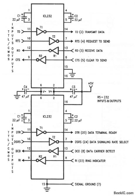
This circuit shows two ICL232s that are combined to accommodate four pairs of inputs/outputs. Notice that each circuit requires two charge-pump capacitors C1/C2, but can share common reservoir capacitors C3/C4. Harris Semiconductors, Data Acquisition 1991 p 137. (View)
View full Circuit Diagram | Comments | Reading(674)
Simple_duplex_RS_232_port
Published:2009/7/19 22:19:00 Author:Jessie
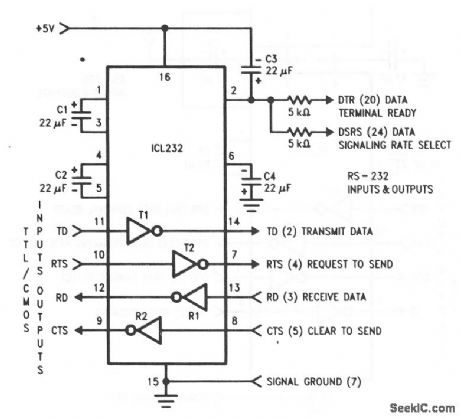
This circuit shows an ICL232 that is connected as a simple duplex RS-232 port with CTS/RTS handshaking. Fixed output signals, such as DTR (data terminal ready) and DSRS (data signaling rate select), are generated by driving them through a 5-kΩ resistor that is connected to V+. Harris Semiconductor. Data Acquisition 1991 p 136 (View)
View full Circuit Diagram | Comments | Reading(1643)
LCD_interface_using_an_ICM7217A_a_DF411_and_a_CD4011
Published:2009/7/19 22:19:00 Author:Jessie
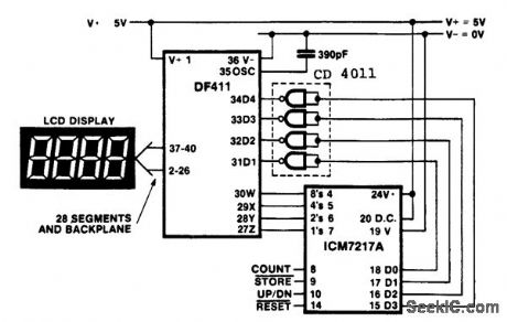
LCD interface using an ICM7217A, a DF411 and a CD4011.Total system power consumption is less than 5 mW, Common-cathode devices should be used since the digit drivers are CMOS, while in common-anode devices the digit drivers are NPN devices and will not provide full logic swing (courtesy Intersil, Inc.). (View)
View full Circuit Diagram | Comments | Reading(1023)
Simple_thermometer
Published:2009/7/19 22:19:00 Author:Jessie
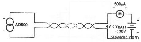
With the connections as shown, the meter displays directly current output in degrees Kelvin. Using the AD590J, the sensor output is within ±10° over the entire range. Harris Semiconductors. Data Acquisition 1991 p. 12-10 (View)
View full Circuit Diagram | Comments | Reading(721)
| Pages:113/291 At 20101102103104105106107108109110111112113114115116117118119120Under 20 |
Circuit Categories
power supply circuit
Amplifier Circuit
Basic Circuit
LED and Light Circuit
Sensor Circuit
Signal Processing
Electrical Equipment Circuit
Control Circuit
Remote Control Circuit
A/D-D/A Converter Circuit
Audio Circuit
Measuring and Test Circuit
Communication Circuit
Computer-Related Circuit
555 Circuit
Automotive Circuit
Repairing Circuit