
power supply circuit
Index 104
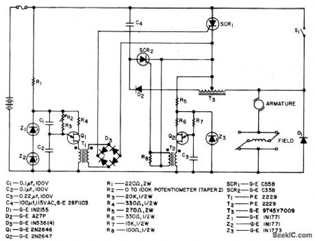
Automotive_regulated_battery_charger
Published:2009/7/17 3:42:00 Author:Jessie
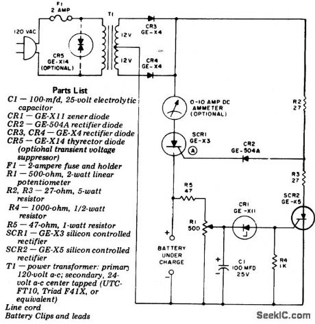
Automotive regulated battery charger. Adjust R1 for a fully charged battery voltage. This inexpensive unit can charge any 12-volt lead-add battery. Should the battery become discharged while the charger is connected the unit will come back on again to recharge the battery (courtesy General Electric Company). (View)
View full Circuit Diagram | Comments | Reading(821)
25_kHz_nicad_battery_charger_with_third_electrode_sensing
Published:2009/7/17 3:40:00 Author:Jessie
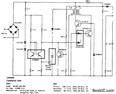
25 kHz nicad battery charger with third-electrode sensing(courtesy Motorola semiconductor Products Inc.). (View)
View full Circuit Diagram | Comments | Reading(708)
MAIN_GATE_MVBR_WITH_TRIODE_LIMITER
Published:2009/7/17 3:39:00 Author:Jessie
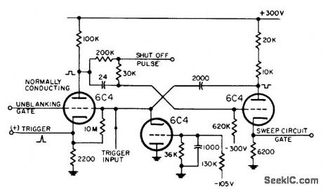
Triode connected to grid of normally-on tube limits swing of voltage. Plate of shutoff tube is tied to point in d-c coupling network between plate and grid, to give greater flexibility in setting plate voltage level of shutoff tube.-NBS, Handbook Preferred Circuits Navy Aeronautical Electronic Equipment, Vol. 1, Electron Tube Circuits, 1963, p N10-5. (View)
View full Circuit Diagram | Comments | Reading(671)
Tachometer
Published:2009/7/17 3:39:00 Author:Jessie

This circuit uses two sections of an XR-13600 (Fig. 11-1b) to form a tachometer or frequency-to-voltage converter. The input is triggered by a positive-going waveform. The maximum FIN is limited by the time required to charge Ct from VL to VH with a current of IB, where VL and VH represent the maximum-low and maximum-high output voltage swing of the XR-13600. D1 provides a discharge path for Ct when A1 switches low. EXAR Corporation Databook 1990 p 5-256 (View)
View full Circuit Diagram | Comments | Reading(2950)
MODEL_TRAIN_CROSSING_INCANDESCENT_FLASHER
Published:2009/7/17 3:38:00 Author:Jessie
This simple circuit can operate the incandescent bulbs in a railroad-crossing flasher. (View)
View full Circuit Diagram | Comments | Reading(866)
TUNNEL_DIODE_MONOSTABLE
Published:2009/7/17 3:38:00 Author:Jessie
Used as pulse-controlled oscillator. Power consumption is very low.- Transistor Manual, Seventh Edition, General Electric Co., 1964, p 366. (View)
View full Circuit Diagram | Comments | Reading(785)
12_conbattery_charger_with_20_ampere_PMS_maximum
Published:2009/7/17 3:37:00 Author:Jessie
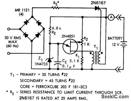
12-conbattery charger with 20-ampere PMS maximum.ms circuits a simple relaxation oscillator using a UJT,The circuit will not work unless the polarity of the battery is observed when connected(courtesy Motorola Semiconductor Products Inc.). (View)
View full Circuit Diagram | Comments | Reading(958)
HIGH_POWER_ONE_SHOT
Published:2009/7/17 3:37:00 Author:Jessie
Operates from random-amplitude (10 to 28 V) square-wave input having 1 to 6.5 sec random duration, and switches 20-W load for adjustable period of 5 to 200 millisec. Can easily be adapted for transient detection, pulse-width adjustment, and time delays.-G. T. Pennell, High-Power One-Shot Multi, EEE, 12:9, p 62. (View)
View full Circuit Diagram | Comments | Reading(765)
SHUTTLE_TRACK_CONTROLLER
Published:2009/7/17 3:36:00 Author:Jessie
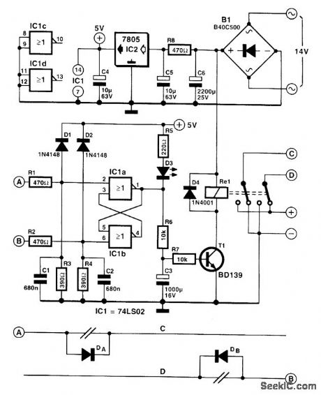
This circuit enables a model train to shuttle continuously between two tracks. When the train travels from left to right across the track in the lower part of the diagram, the lower rail (D) is connected to the positive supply line. After it has passed diode DB, the train will stop. Because the loco-motive short-circuits the diode when it passes the break in the rail, a short positive pulse is generated on rail section B. The pulse is used to set bistable IC1, whereupon D3 goes out and capacitor C3 is being charged. When the potential across the capacitor rises to a sufficiently high level, transistor T1 switches on, whereupon the relay is energized. This causes the polarity of rails C and D to be re-versed. Diode DB is then on, so the train departs in the direction of A. Rail C is then connected to the positive supply rail; so when the train passes diode DA, a positive pulse is generated on rail section A. This pulse is used to reset the biastable, whereupon the LED lights and the relay is deenergized. After the relay contacts have reversed the polarity of C and D again, diode DA comes on and the train departs again in the direction of B. (View)
View full Circuit Diagram | Comments | Reading(1579)
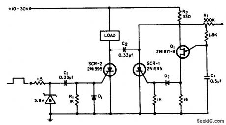
12_15_V_AT_500_W
Published:2009/7/17 3:36:00 Author:Jessie
Developed to permit operation of high-power mobile solid-state amateur transmitter in home. Current sensing is done with 15-milliohm resistor R16. Short-circuit cutoff is provided by regulator along with current limiting through R16. Output voltage begins dropping as load exceeds 35 A. When voltage drops below 8 V, Q1 turns off and SCR1 turns on, cutting output power. Power supply must be turned off to unlatch SCR1. For over-voltage shutdown, CR2 starts conducting above 16 V, turning on SCR2 and activating relay K1 to cut off main DC supply. Article gives construction details. T1 has 22-V secondary.-C. C. Lo, 500-Watt Regulated Power Supply, Ham Radio, Dec. 1977, p 30-32. (View)
View full Circuit Diagram | Comments | Reading(1026)
TESLA_COIL_SECONDARY_RECEIVER
Published:2009/7/17 3:36:00 Author:Jessie
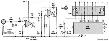
Here's a Tesla-coil secondary to try: Wind 750 turns of 24-gauge enameled magnet wire onto an 18 long piece of 1.9 outer-diameter PVC pipe. The large coil has an inductance of about 2800 mH, with a self-capacitance of about 20 pF. One end of the coil should be earth grounded. Put a metal ball (a drawer pull knob or doorknob) at the other end. Now attach it to a crystal radio.The RF is detected by a 1N34 germanium diode, D1, and you will note that signal strength is high. What you should hear is one or possibly several AM radio stations, depending on the coil, the radio frequencies in your area, and distance to the transmitter(s). (View)
View full Circuit Diagram | Comments | Reading(2364)
RECEIVER_FRONT_END_SELECTOR
Published:2009/7/17 3:34:00 Author:Jessie
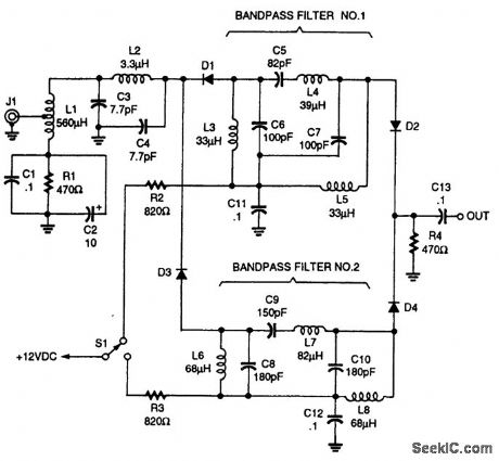
Receiver front-end selection can be accomplished by using PIN-diode switches (as shown). The PIN diodes can be MV3404 or similar types. (View)
View full Circuit Diagram | Comments | Reading(706)
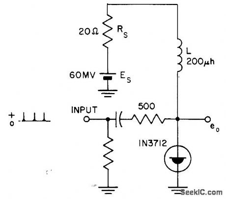
JONES_CHOPPER_FOR_BATTERY_POWERED_VEHICLE
Published:2009/7/10 22:58:00 Author:May
Uses variable-frequency constant pulse-width system that starts reliably and provides smooth acceleration. At low speeds, on time of chopper, in series with d-c series motor,is much less than off time so average motor voltage is low. Potentiometer R2 controls ratio of on to off limes for speed control. Silicon Controlled Rectifier Manual, Third Edition, General Electric CO,1964, p173. (View)
View full Circuit Diagram | Comments | Reading(1729)
136_V_AT_1_A
Published:2009/7/17 4:11:00 Author:Jessie
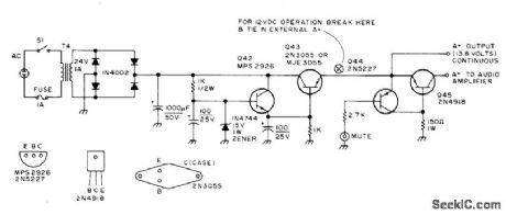
Used in all-band double-conversion superheterodyne receiver for AM, narrow-band FM, CW, and SSB operation Simple transformer-rectifier-filter circuit is followed by zener-referenced Darlington pair. When transmitter of amateur station is on air, muting is accomplished by grounding base of Q44 through 2.7K resistor, which turns off Q45 and kills A+ to audio amplifier.-D. M. Eisenberg, Build This All-Band VHF Receiver, 73 Magazine, Jan. 1975, p 105-112. (View)
View full Circuit Diagram | Comments | Reading(1810)
BISTABLE__TD_TRANSISTOR
Published:2009/7/17 4:11:00 Author:Jessie
Fast switching speed of tunnel diode contributes to output waveform.- Transistor Manual, Seventh Edition, General Electric Co., 1964, p 367. (View)
View full Circuit Diagram | Comments | Reading(603)
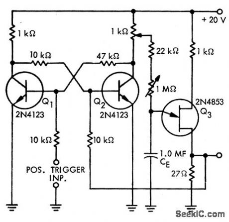
Indicating_one_shot_multivibrator
Published:2009/7/17 4:12:00 Author:Jessie
Indicating one-shot multivibrator. The circuit delivers a 0.5-second flash from the LED every time the pushbutton makes contact (courtesy National Semiconductor Corporation). (View)
View full Circuit Diagram | Comments | Reading(623)
3_V_POWER_SUPPLY_FOR_PORTABLE_RADIOS
Published:2009/7/10 22:25:00 Author:May
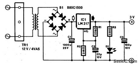
Most small portable radios require a 3-V supply, which is normally provided by two AA or AAA bat-teries. Because rechargeable batteries are an option with many of these radios, most of them are fitted with a charger socket. When such radios are used in a stationary condition (e.g., in the kitchen or in the office), it is useful (and economical) to use the mains-operated supply described here.
The supply is small enough to be fitted inside the radio or in a mains adapter case (less than trans-former). Voltage regulator IC1 is adjusted for an output of 3 V by resistors R1 and R2, which are decou-pled by C2. Capacitor C3 provides additional filtering. Diode D1 indicates whether the unit has been connected to the mains. The diode also provides the load necessary for the regulator to function properly; in its absence, the secondary voltage of the transformer might become too high when the unit is not loaded.
The transformer should be a short-circuit-proof miniature type, which is rated at 12 V and 4.5 VA.The secondary voltage is slightly higher than needed for a radio, but this reserve is useful when the unit is used with a cassette or CD player. It is advisable to check the output voltage of the unit when it is switched on for the first time before connecting it to a radio or cassette player. (View)
View full Circuit Diagram | Comments | Reading(1261)
One_shot_multivibrator_using_a_UJT
Published:2009/7/17 4:13:00 Author:Jessie
One-shot multivibrator using a UJT. This circuit is insensitive to bias voltage changes (courtesy Motorola Semiconductor Products Inc.). (View)
View full Circuit Diagram | Comments | Reading(771)
RADAR_TRANSPONDER
Published:2009/7/17 4:13:00 Author:Jessie
Used in missiles for tracking during test firing on range. Semi-conductor modulator minimizes power drain and thereby reduces heating in transponder, while providing r-f output pulse having extremely fast rise and fall times. Delay stability gives range accuracy of 1 yard.-L. Diven, Solid-Stage Modulator Feeds Subminature. Transponder, Electronics, 33:27, p 48-51. (View)
View full Circuit Diagram | Comments | Reading(1490)
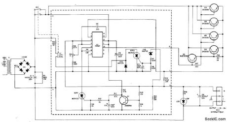
Fire_siren_using_an_LM3909_chip
Published:2009/7/17 4:47:00 Author:Jessie
Fire siren using an LM3909 chip. Circuitry inside dashed lines is the LM3909.This circuit produces a rapidly rising sound when pressing the pushbutton and a coasting sound upon release (courtesy National Semiconductor Corporation). (View)
View full Circuit Diagram | Comments | Reading(764)
| Pages:104/291 At 20101102103104105106107108109110111112113114115116117118119120Under 20 |
Circuit Categories
power supply circuit
Amplifier Circuit
Basic Circuit
LED and Light Circuit
Sensor Circuit
Signal Processing
Electrical Equipment Circuit
Control Circuit
Remote Control Circuit
A/D-D/A Converter Circuit
Audio Circuit
Measuring and Test Circuit
Communication Circuit
Computer-Related Circuit
555 Circuit
Automotive Circuit
Repairing Circuit