
power supply circuit
Index 105
FAIL_SAFE_COMMUNICATIONS_SQUELCH_CIRCUIT
Published:2009/7/17 4:47:00 Author:Jessie
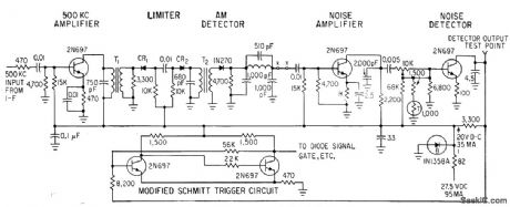
Circuit adjusts automatically to changing noise levels in point-to-point vhf and uhf receivers while suppressing noise when no carrier is present, but stays open when receiver gain is below threshold level of 0.7 microvolt over range of 108.95 to 135.95 Mc. Schmitt trigger gives fast turn-on and turn-off of receiver audio output at predetermined carrier-to-noise ratios.-H. G Michael, Fail-Safe Squelch Circuit Adapts to Changing Noise levels, Electronics, 36:1, p 88-91. (View)
View full Circuit Diagram | Comments | Reading(814)
Whooper_siren_using_two_LM3909_chips
Published:2009/7/17 4:46:00 Author:Jessie
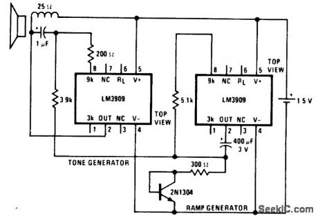
Whooper siren using two LM3909 chips (courtesy National Semiconductor Corporation). (View)
View full Circuit Diagram | Comments | Reading(784)
Electronic_trombone_using_an_LM3909_chip
Published:2009/7/17 4:46:00 Author:Jessie
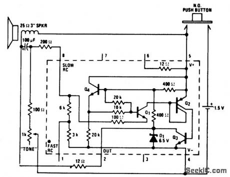
Electronic trombone using an LM3909 chip. Circuitry inside dashed lines is the LM3909. The location and surroundings of the speaker determine the frequency output. Construct a cubical box roughly 64 cubic inches with one end that is able to slide in and out like a piston. The box should be stiffened with thin layers of pressed wood. Minimum volume should be 10 cubic inches. Speaker, circuit and battery should be mounted in the sliding end. A tube 21/2 inches long with an inside diameter of 5/16 inch should be provided to bleed air in and out as the piston moves (courtesy National Semiconductor Corporation). (View)
View full Circuit Diagram | Comments | Reading(804)
NEGATIVE_INPUT_CURRENT_REGULATOR
Published:2009/7/17 4:45:00 Author:Jessie
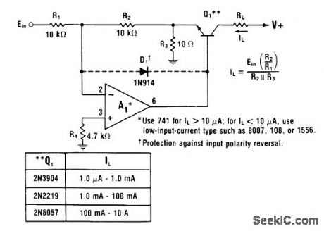
Opamp is used as inverter starting current-boosting transistor to provide positive supply voltage. Load current range depends on transistor used.R3 forcesQ1 to conduct much heavier current than feedback current, as required for high load current. Current gain depends on ratio of R2 to R3-W. G. Jung, IC Op-Amp Cookbook, Howard W. Sams, Indianapolis, IN, 1974, p 176-177. (View)
View full Circuit Diagram | Comments | Reading(771)
1_KC_NOISE_FIGURE_TEST_SET
Published:2009/7/17 4:44:00 Author:Jessie
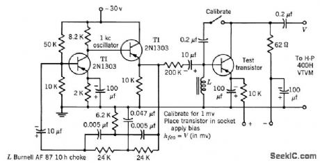
Used in measuring low-frequency Gommon-emitter short-circuit forward current transfer ratio h-feo, which is one of the parameters having greatest effect on transistor noise figure. -Texas Instruments Inc., Transistor Circuit Design, McGraw-Hill, N.Y., 1963, p 304. (View)
View full Circuit Diagram | Comments | Reading(759)
Norton_comparator_for_positive_input_voltages
Published:2009/7/17 4:43:00 Author:Jessie
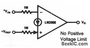
This circuit uses one section of an LM3900 to form an inverting comparator. The reference voltage must be larger than VBE (typically 0.5 V), but there is no limit as long as the input resistor is large enough to guarantee that the input current does not exceed 200μA. National Semiconductor Linear Applications Handbook 1991, p 243. (View)
View full Circuit Diagram | Comments | Reading(668)
100_mA_TRACKING
Published:2009/7/17 4:42:00 Author:Jessie
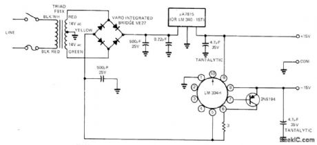
Circuit uses +15 V from μA7815 positive fixed-output regulator as external reference for LM304 negative regulator operating with outboard current-carrying PNP transistor. Arrangement requires only one center-tapped transformer winding yet gives required tracking of voltages. Output can be boosted to 200 mA by using larger bridge rectifier section.-H. Olson, Simple ±15V Regulated Supply Provides Tracking, EDN Magazine, March 20, 1973, p 87. (View)
View full Circuit Diagram | Comments | Reading(1721)
_5_V_WITH_LM3OOH
Published:2009/7/17 4:40:00 Author:Jessie
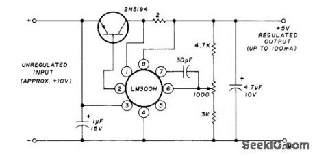
Series power transistor and National IC voltage regulator provide up to 100 mA. Improved version of regulator,LM305H, may be substituted.-H. Olson, Power-Supply Servicing, Ham Radio, Nov.1976, p 44-50. (View)
View full Circuit Diagram | Comments | Reading(1027)
6_30_V_AT_500_mA
Published:2009/7/17 4:40:00 Author:Jessie
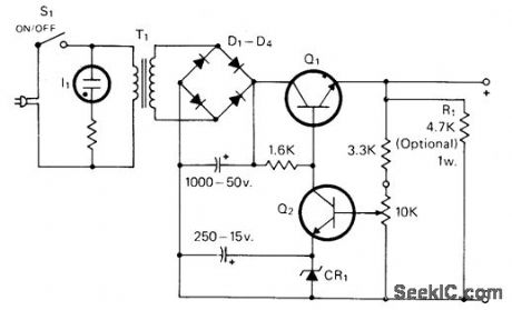
Zener used for CR1 should be rated 1 V less than desired minimum voltage, at 300 mW. R1 improves regulation at low cur rent levels. Current-limiting value is about 1 A. Diodes are 50-PIV 1-A silicon. I1 is 117-V neon lamp, Q1 is any 15-W NPN power transistor. Q2 is 2N697 or equivalent. T1 is power transformer with 24-V secondary at 0.5 A.-J. Huffman, The Li'I Zapper-a Versatile Low Voltage Supply, CQ, Nov. 1977, p 44. (View)
View full Circuit Diagram | Comments | Reading(764)
AUXILIARY_SUPPLY
Published:2009/7/10 21:54:00 Author:May
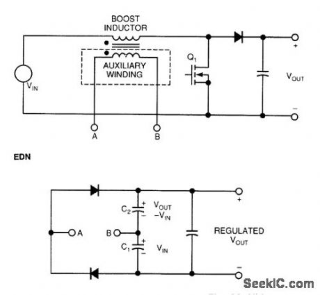
Many power-factor-correction circuits use a boost converter to generate a regulated dc output voltage from the ac line input while forcing the load to draw sinusoidal current, which maximizes the power factor.
This circuit's full-wave rectifter the auxiliary winding's output to completely cancel out line variations and provide a regulated output voltage. The circuit essentially sums the two phases of the boost inductor's voltage to eliminate the 120-Hz components. The regulated output tracks the power-factor-controlled pre-regulator output voldage and it can be used in the corrected output voltage's feedback loop.
An isolated auxiliary winding consists of the desired number of turns wound on the boost inductor. You can vary the exact value of the auxiliary supply's output voltage by adjusting or scaling the auxiliary wind-ing's number of tums. Figure 63-4(b)'s rectifter develops two separate, but individually unregulated volt-ages, across capacitors C1 and C2. Each of these voltages varies in amplitude at twice the ac-line frequency. When switch Q1 is on, the boost inductor connects directly across the input supply, and a volt-age proportional to the instantaneous input voltage develops across capacitor C1.
Once the switch tums off, the inductor voltage reverses and clamps to a voltage equal to VOUT -VIN. During this interval, a voltage proportional to VOUT -VIN develops across C2. The sum of these two capac-itor voltages produces a regulated auxiliary voltage that is proportional to VOUT. The voltage across the output capacitor equals VIN+ (VOUT- VIN), which cancels the input-line variations. (View)
View full Circuit Diagram | Comments | Reading(1042)
UNIVERSAL_SUPPLY
Published:2009/7/17 4:38:00 Author:Jessie
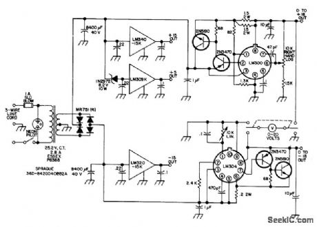
Provides three different fixed voltages and two variable, each regulated and each current-limited at 1.5 A for use on experimenter's bench. Use heatsinks for fixed voltage regulators and for output transistors. - N. Calvin, Universal Power Supply, 73 Magazine, Aug. 1974, p 65-66. (View)
View full Circuit Diagram | Comments | Reading(861)
Norton_phase_locked_loop
Published:2009/7/17 4:36:00 Author:Jessie

This circuit uses three sections of an LM3900 to form a phase-locked loop (with a center frequency of about 3 kHz using the values shown). National Semiconductor Linear Applications Handbook 1991 p 239 (View)
View full Circuit Diagram | Comments | Reading(960)
MILLIOHMMETER
Published:2009/7/17 4:35:00 Author:Jessie
Substitution of transistors for diodes in rectifier circuit of a-c milliohm-meter gives significant increase in sensitivity and linearity. Uses inexpensive milliammeter.-P. Lefferts, Transistors Replace Diodes in Milliohmmeter Circuit, Electronics, 39:18, p 97. (View)
View full Circuit Diagram | Comments | Reading(3091)
Norton_free_running_staircase_generator
Published:2009/7/17 4:34:00 Author:Jessie

This circuit uses four sections of an LM3900 to form a free-running staircase generator. When the output exceeds about 80% of V+, a 100-μs reset pulse is generated, and the staircase output is caused to fall to about zero volts. The next pulse from amplifier I then starts a new stepping cycle. National Semiconductor, Linear Applications Handbook 1991, p 236 (View)
View full Circuit Diagram | Comments | Reading(986)
Norton_slow_sawtooth_waveform_generator
Published:2009/7/17 4:32:00 Author:Jessie
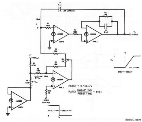
This circuit uses four sections of an LM3900 to form a generator with very slow sawtooth waveforms (which can be used to generate long time-delay intervals, as one application). The reset signal is applied to amplifier 3 through R10, and R5 adjusts the sweep. With the values shown, the 10-nA current and 1-μF capacitor establishes a sweep rate of 100 s/V. R4 provides a reset rate of 0.7 s/V.National Semiconductor, Linear Applications Handbook, 1991 p 234. (View)
View full Circuit Diagram | Comments | Reading(921)
RESISTANCE_COMPARATOR
Published:2009/7/17 4:32:00 Author:Jessie
Known and unknown resistances are connected alternately, across shock-excited oscillator by flip-flopdriven relay, and damping effect is observed on cro.-A. Kislovsky, Comparing Resistances with Oscillator and Oscilloscope, Electronics, 34:23, p 118. (View)
View full Circuit Diagram | Comments | Reading(1318)
DISTANCE_MARK_GENERATOR_1
Published:2009/7/17 4:32:00 Author:Jessie
Uses switched Hartley oscillator, mvbr-type trigger shaper, and parallel-triggered blocking oscillator to generate distance marks in airborne search radar. RLC unit is switched to change mark spacting.-NBS, Handbook Preferred Circuits Navy Aeronautical Electronic Equipment, Vol. 1, Electron Tube Circuits, 1963, p N8-1. (View)
View full Circuit Diagram | Comments | Reading(640)
VARIABLE_SWEEP_LENGTH
Published:2009/7/17 4:30:00 Author:Jessie

Operates with sweep lengths varying by factor of 8 to 1. Supplies 1,100 v at 160 ma for 0.5-mile range and 400 v at 270 ma for 4-mile range.-R. F. P. Smith, Airport Radar Has High Resolution, Electronics, 32:14, p 64-69. (View)
View full Circuit Diagram | Comments | Reading(768)
FAR_END_OF_LINE_MODULATOR_CLIPPER
Published:2009/7/17 4:29:00 Author:Jessie
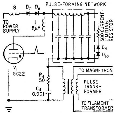
In variation of diode modulator, clipper diodes D9 and D10 are connected to far end of pulse-forming network, for improved perform once. Choke L in plate circuit of thyratron limits rate of rise of thyratron current.-M. G. Gray, Using Silicon Diodes in Radar Modulators, Electronics, 32:24, p 70-72. (View)
View full Circuit Diagram | Comments | Reading(1672)
PULSE_WIDTH_ENCODER
Published:2009/7/17 4:28:00 Author:Jessie
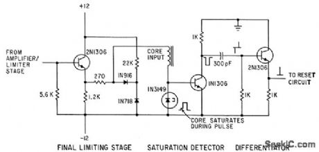
Pulse widths in microsecond range are amplitude-limited and dumped into magnetic core. When core saturates, signal is recorded on magnetic tape and core is reset for next series of pulses. The number of changes of state between saturation points gives the number of pulses for core saturation, from which pulse width can be computed.-W. L. Carter and P. J. Knoke, Pulse-Width Measurements, Electronics, 35:43, p 51-53. (View)
View full Circuit Diagram | Comments | Reading(806)
| Pages:105/291 At 20101102103104105106107108109110111112113114115116117118119120Under 20 |
Circuit Categories
power supply circuit
Amplifier Circuit
Basic Circuit
LED and Light Circuit
Sensor Circuit
Signal Processing
Electrical Equipment Circuit
Control Circuit
Remote Control Circuit
A/D-D/A Converter Circuit
Audio Circuit
Measuring and Test Circuit
Communication Circuit
Computer-Related Circuit
555 Circuit
Automotive Circuit
Repairing Circuit