
power supply circuit
Index 109
Audio_dancing_lights_with_three_channels
Published:2009/7/17 4:51:00 Author:Jessie
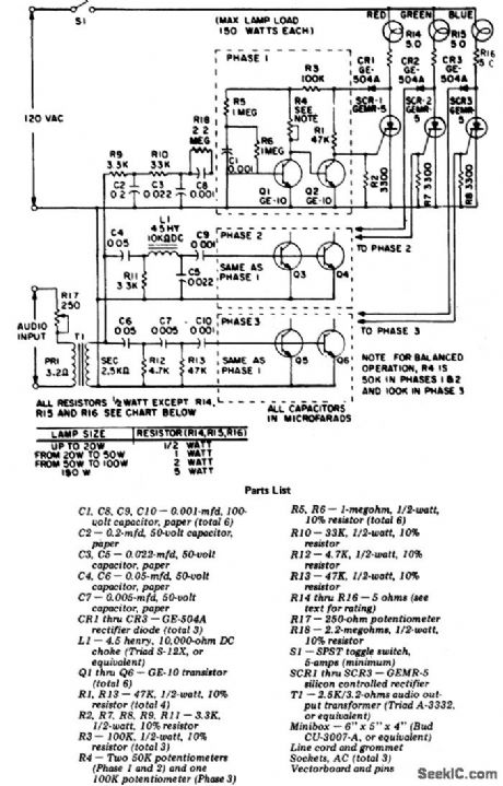
Audio dancing lights with three channels. This circuit uses the audio output from your stereo and separates the high, low and medium frequencies to activate three colored lights. Input sensitivity is controlled by R17 (courtesy General Electric Company). (View)
View full Circuit Diagram | Comments | Reading(1435)
Morse_code_set_using_an_LM3909_chip
Published:2009/7/17 4:50:00 Author:Jessie
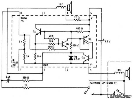
Morse code set using an LM3909 chip. Circuitry inside dashed lines is the LM3909. The three-wire system and parallel telegraph keys allow the user to practice with send/receive switches (courtesy National Semiconductor Corporation). (View)
View full Circuit Diagram | Comments | Reading(788)
Automotive_burglar_alarm_for_12_volt_negative_ground_systems
Published:2009/7/17 4:49:00 Author:Jessie
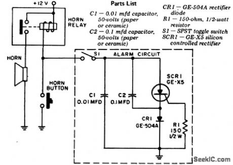
Automotive burglar alarm for 12-volt negative ground systems. The entire alarm circuit (inside dashed lines) can be mounted on the SPST toggle switch. The circuit is triggered whenever any electrical device in the car is turned on. To turn off the alarm it is necessary to turn off S1 or hit the horn button. Mount S1 in the truck (courtesy General Electric Company). (View)
View full Circuit Diagram | Comments | Reading(864)
O1_35V_AT_1A
Published:2009/7/17 4:48:00 Author:Jessie
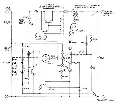
CA3160 serves as error amplifier in continuously adjustable regulator that functions down to vicinity of 0 V. RC network between base of 2N2102 output drive transistor and input source prevents turn-on overshoot. Input regulation is better than 0.01%/V, and regulation from no load to full load is better than 0.005%. Hum and noise output is less than 250μVRMS.- Linear Integrated Circuits and MOS/FET's, RCA Solid State Division, Somerville, NJ, 1977, p 267-269. (View)
View full Circuit Diagram | Comments | Reading(1320)
Light_triggered_photoflash_slave
Published:2009/7/17 4:48:00 Author:Jessie
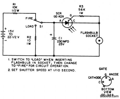
Light-triggered photoflash slave. This circuit is activated when you operate your camera's flash. If a 22.5-volt battery is not available use two 9-volt batteries. To increase the LASCR sensitivity mount it behind a lens or reflector (courtesy General Electric Company). (View)
View full Circuit Diagram | Comments | Reading(1243)
5V_AT_200mA
Published:2009/7/19 21:06:00 Author:Jessie
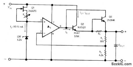
Article gives step-by-step design procedure for developing special opamp regulator when commercial unit meeting desired specifications is not available. Opamp is μA741. Circuit gives good regulation along with short-circuit protection, with less than 2 mV P-P AC ripple. Required input of 20V is obtained from conventional full-wave bridge rectifier with capacitor-input filter.-C. Brogado, IC 0p Amps Simplify Regulator Design, EDN/EEE Magazine, Jan. 15, 1972, p 30-34. (View)
View full Circuit Diagram | Comments | Reading(799)
BOXCAR_DETECTOR
Published:2009/7/19 21:05:00 Author:Jessie
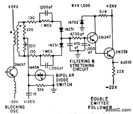
Diodes conduct during range gate interval of 0.2 microsec in portable doppler radar, to connect video signal to filter circuit.-J. Scott, D. Randise, and R. P. Lukacovic, Portable Radar Traces Battlefield Deployment, Electronics, 33:12, p 67-70. (View)
View full Circuit Diagram | Comments | Reading(645)
VARIABLE_DUAL_POLARITY
Published:2009/7/19 21:05:00 Author:Jessie
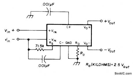
External resistor R0 determines values of positive and negative regulated output voltages provided by Silicon General SG3501 dual regulator.-H. Olson, Second-Generation IC Voltage Regulators, Ham Radio, March 1977, p 31-37. (View)
View full Circuit Diagram | Comments | Reading(979)
PRF_GENERATOR_1
Published:2009/7/19 21:03:00 Author:Jessie
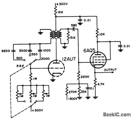
Blocking oscillator operates in range of 200 to 2,000 pps, as radar repetition-rate generator having frequency stability of about 5%. Has positive grid return, although this may decrease frequency stability if heater voltage drops below rated value.-NBS, Handbook Preferred Circuits Navy Aeronautical Electronic Equipment, Vol. 1, Electron Tube Circuits, 1963, p N5-2. (View)
View full Circuit Diagram | Comments | Reading(0)
0_20V_AT_2A
Published:2009/7/19 21:01:00 Author:Jessie
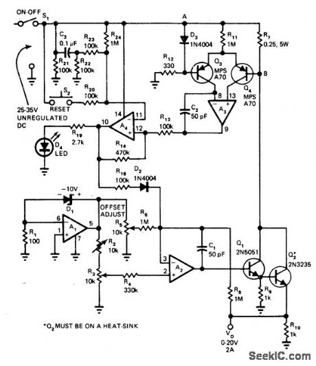
R3 provides control of output voltage for regulator built around LM3900 quad Norton opamp. Output is well regulated against both line and load variations and is free of ripple. Opamp sections A3 and A, provide over current sensing and shutdown functions; after out-put fault is cleared, S2 is closed momentarily to restore output power. Article describes circuit operation and initial setup in detail.-J. C. Han-isko and W. Wiseman, Variable Supply Built Around Quad Amp Outputs 2A, EDN Magazine, June 20, 1976, p 128 and 130. (View)
View full Circuit Diagram | Comments | Reading(780)
LINE_SWEEP_GENERATOR_FOR_ENCODER
Published:2009/7/19 21:00:00 Author:Jessie
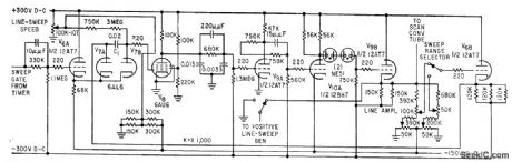
Circuit is basically negative-feedback linearized R.C sawtooth generator in which charging voltage is held constant while negative end of sweep-forming capacitor is driven negative. Amplifier V8-V9A-V10A is direct-coupled throughout. Loop-stabilizing networks pass high-frequency components.-H. W. Gates and A. G. Gatfield, Scan Converter Aids Phone-Line Radar Relay, Electronics, 32:16, p 48-51. (View)
View full Circuit Diagram | Comments | Reading(652)
5V_AT_1A
Published:2009/7/19 20:59:00 Author:Jessie
Use of Darlington at output boosts power rating of standard opamp voltage regulator circuit. Article gives step-by-step design procedure. With μA741 opamp, circuit gives good regulation along with short-circuit protection. AC ripple is less than 2 mV P-P. Required input of 30V is obtained from conventional full-wave bridge rectifier with capacitor-input filter.-C, Brogado, IC Op Amps Simplify Regulator Design, EDN/EEE Magazine, Jan. 15, 1972, p 30-34. (View)
View full Circuit Diagram | Comments | Reading(928)
15_V_AT_200mA
Published:2009/7/19 20:57:00 Author:Jessie
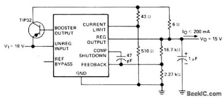
Linear regulator using Texas Instruments SN52105, SN72305, or SN72376 is connected for foldback current limiting. Regulators are interchangeable with LM105, LM305, and LM376 respectively. Load regulation is 0.1%, and input regulation is 0.1%/V.- The Linear and Interface Circuits Data Book for De-sign Engineers, Texas Instruments, Dallas, TX, 1973, p 5-9. (View)
View full Circuit Diagram | Comments | Reading(1210)
FLYBACK_BLANKING
Published:2009/7/19 20:56:00 Author:Jessie
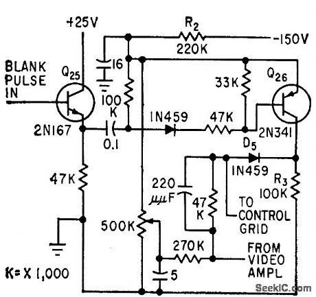
Amplifies blanking pulse from monostable mvbr sweep circuitto level required for blanking crt screen. Q26, normally nonconducting, is driven to saturation by blanking pulse, thereby applying high negative voltage to crt control grid.-C. E. Veazie, Transistorized Radar Sweep Circuits Using Low Power, Electronics, 32:26, p 46-47. (View)
View full Circuit Diagram | Comments | Reading(724)
PULSED_X_BAND_MAGNETRON
Published:2009/7/19 20:54:00 Author:Jessie
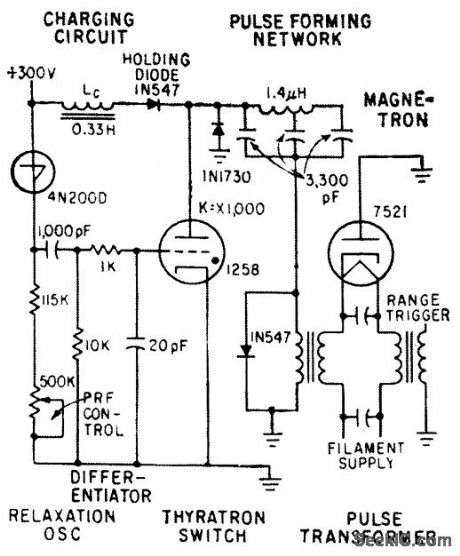
Differentiator forms sharp 2-microsec pulse at trailing each of each sawtooth waveform generated by R-C charging circuit and Shockley pnpn diode. Pulse triggers thyratronto discharge pulse-forming network, and new pulse is stepped up to 4,500 v by pulse transformer for magnetron.-J. Scott, D. Randise, and R. P. Lukacovic, Portable Radar Traces Battlefield Deployment, Electronics, 33:12, p 67-70. (View)
View full Circuit Diagram | Comments | Reading(2044)
DOUBLE_PULSE_GENERATOR
Published:2009/7/19 20:52:00 Author:Jessie
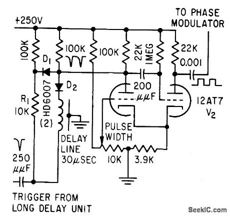
Used in responder-interrogator range computer to produce pair of 15-microsec-wide pulses spaced 30 microsec. Monostable mvbr receives two triggers, one through 30-microsec delay line, and produces 15-microsec pulse for each trigger received.-H. Vantine, Jr., and E.C. Johnson, Modified Transceivers Compute Distance, Electronics, 31:37, p 94-98. (View)
View full Circuit Diagram | Comments | Reading(765)
KLYSTRON_SERVO
Published:2009/7/19 20:51:00 Author:Jessie

Simple three-tube modecentering servo is only control required for local-oscillator klystron in wide-band receiver of short-pulse radar system.-C. D. Hardin and J. Salerno, Miniature X-Band Radar Has High Resolution, Electronics, 32:5, p 48-51. (View)
View full Circuit Diagram | Comments | Reading(766)
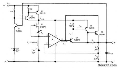
_5V_AT_3A
Published:2009/7/19 20:50:00 Author:Jessie
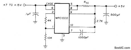
Uses Motorola MPC1000 positive voltage regulator to provide high current required for large TTL project. Current-limiting resistor RSC is in range of 0.66 to 0.066 ohm. Use copper wire about 50% longer than calculated length and shorten step by step until required pass current is obtained; thus, start with 25 ft of No. 16, 15 ft of No. 18, 10ft of No. 20, or 6 ft of No. 22.-G. L. Tater, The MPC1000-Super Regulator, Ham Radio, Sept. 1976, p 52-54. (View)
View full Circuit Diagram | Comments | Reading(761)
12_37V_AT_15A
Published:2009/7/19 20:49:00 Author:Jessie
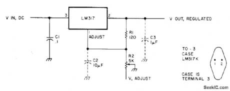
Uses National LM317 adjustable three-terminal positive voltage regulator. Output voltage is determined by ratio of R1 and R2. Output can be adjusted from 37 V down to 1.2V with R2. If DC input is 40V, regulation is about 0.1% at all settings when going from no load to full load. Regulator includes overload and thermal protection. If current limit is exceeded, regulator shuts down. C2 and C3 are optional; C2 improves ripple rejection, and ca prevents instability when load capacitance is between 500 and 5000 pF.-Adjustable Bench Supply, 73Magazine, Dec. 1977, p 192-193 (View)
View full Circuit Diagram | Comments | Reading(1052)
Oscilloscope_calibrator_using_an_LM3909_chip
Published:2009/7/19 20:25:00 Author:Jessie
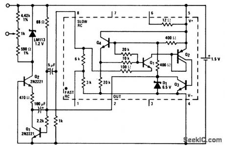
Oscilloscope calibrator using an LM3909 chip. The output is a clean rectangular wave that is exactly 1 volt peak to peak. The rectangular wave is approximately 1.5 ms on and 5.5 ms off. Battery life from a 1.5-volt D-cell is approximately 500 hours (courtesy National Semiconductor Corporation). (View)
View full Circuit Diagram | Comments | Reading(696)
| Pages:109/291 At 20101102103104105106107108109110111112113114115116117118119120Under 20 |
Circuit Categories
power supply circuit
Amplifier Circuit
Basic Circuit
LED and Light Circuit
Sensor Circuit
Signal Processing
Electrical Equipment Circuit
Control Circuit
Remote Control Circuit
A/D-D/A Converter Circuit
Audio Circuit
Measuring and Test Circuit
Communication Circuit
Computer-Related Circuit
555 Circuit
Automotive Circuit
Repairing Circuit