
power supply circuit
Index 121
REFERENCE_OUTPUT_IN_05_V_STEPS
Published:2009/7/20 4:29:00 Author:Jessie
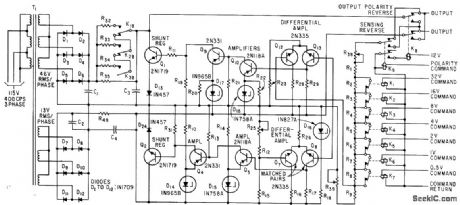
Eight command signals combined in a binary manner provide stable reference output voltage r from -63.5 v to +63.5 v in 0.5-v steps, with regulation of 0.05% for 5% change in input voltage. System uses two independent d-c power supplies, one delivering fixed 20 v and the other from 20 to 83.5 v in 0.5-v in crements.-M. Beebe and J. Miller, Reference. Supply Delivers Half-Volt Increments, Electronics,35:18, p41-43. (View)
View full Circuit Diagram | Comments | Reading(717)
100_kHz_MULTIPLE_OUTPUT_SWITCHING_POWER_SUPPLY
Published:2009/7/9 5:02:00 Author:May
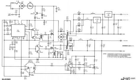


The power supply uses two VN4000A 400-V MOSPOWER FETs in a half-bridge power switch configuration. Outputs availableare+5 V at 20A and±15V or±12 V at 1 A,Since linear three-termlinal regulators are used for the low-current outputs,either±12V or±15V can be made available with a simple change h the transformer secondary windings. A TL494 switching regulator IC provides pulse-width modulation control and drive signals for the power supply.The upper MOSPOWER FET,Q7,In the powerswitch stage is driven by a simple transformer driven by a simple transformer drive circuit.The lower MOS,Q6,smce it is ground referenced,is directly driven fromthe control IC. (View)
View full Circuit Diagram | Comments | Reading(3479)
Four_channel_sequencing_multiplexer
Published:2009/7/20 6:21:00 Author:Jessie
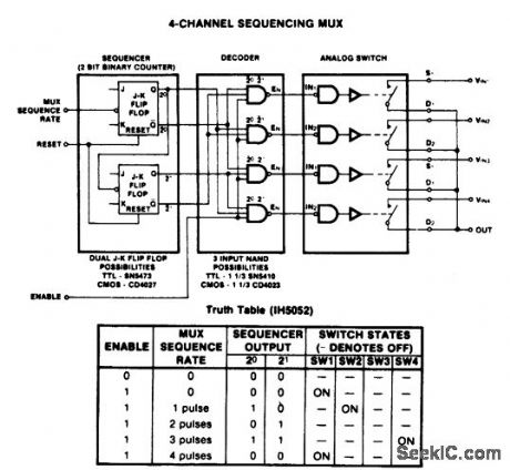
Four-channel sequencing multiplexer. The analog switch package is an Intersil IH5052 16-pin CMOS DIP (courtesy Intersil, Inc.). (View)
View full Circuit Diagram | Comments | Reading(851)
2_level_16_channel_multiplexer
Published:2009/7/20 6:20:00 Author:Jessie

2-level 16-channel multiplexer (courtesy Motorola Semiconductor Products Inc.). (View)
View full Circuit Diagram | Comments | Reading(689)
2_input_analog_multiplexer_using_an_MC14007_dual_pair_plus_inverter
Published:2009/7/20 6:18:00 Author:Jessie
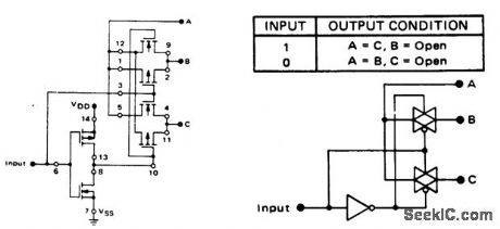
2-input analog multiplexer using an MC14007 dual pair plus inverter (courtesy Motorola Semiconductor Products Inc.). (View)
View full Circuit Diagram | Comments | Reading(682)
8_cannel_analog_multiplexer_with_two_methods_of_selection
Published:2009/7/20 6:17:00 Author:Jessie

8-cannel analog multiplexer with two methods of selection. Two MC14016s as shown in (a) can be connected for an 8-channel multiplexer. The MC14022 octal counter in (b) is used for time division multiplexing (stepping switch) and each channel is on for one period of the scanning clock. The MC14028 decoder is used for control in applications requiring selection with a 3-bit binary code (courtesy Motorola Semiconductor Products Inc.). (View)
View full Circuit Diagram | Comments | Reading(1752)
Positive_voltage_regulator_5_volts_with_foldback_current_limiting_using_an_ECG915_or_ECG915D
Published:2009/7/20 6:03:00 Author:Jessie
Positive voltage regulator (5 volts) with foldback current limiting using an ECG915 or ECG915D.For a ±5% fixed output R1 is 2.15 ohms and R2 is 4.99 ohms(courtesy GTE Sylvania Incorporated). (View)
View full Circuit Diagram | Comments | Reading(720)
0_10_V_TWO_ZENER
Published:2009/7/20 6:02:00 Author:Jessie
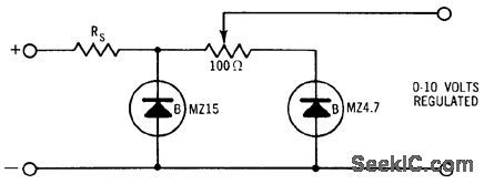
Simple arrangement provides source of well-regulated adjustable voltage. First zener diode tends to act as pre-regulator, improving dynamic regulation.- Zener Diode Handbook, International Rectifier Corp., 1960, p 54. (View)
View full Circuit Diagram | Comments | Reading(662)
Positive_precision_voltage_regulator_15_volts_using_an_ECG915_or_ECG915D_IC
Published:2009/7/20 6:01:00 Author:Jessie
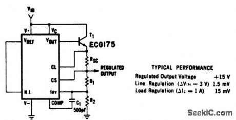
Positive precision voltage regulator (15 volts) using an ECG915 or ECG915D IC.R1 is 7.87 ohms, R2 is 7.15 ohms and Rsc is 10 ohms for a ±5% fixed output (courtesy GTE Sylvania Incorporated). (View)
View full Circuit Diagram | Comments | Reading(578)
20000_V_INDUCTIVE_STORAGE_SUPPLY
Published:2009/7/20 5:55:00 Author:Jessie
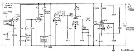
Consists of shunt-regulated electronically switched inductive energy storage system in which coil L1 is charged through vacuum switch. When high voltage is needed, V2 is fired to deionize V1. Cathode capacitor of V2 is then charged to 20,000 V by coil current, at which time electronic feedback regulator in shunt with L1 draws current to maintain constant output voltage.-R. L. Gamblin, Ohmic Heating Circuits for Plasma Physics, Electronics, 32:41, p 57-59. (View)
View full Circuit Diagram | Comments | Reading(740)
PREFERRED_300_V_D_C_REGULATOR
Published:2009/7/20 6:06:00 Author:Jessie
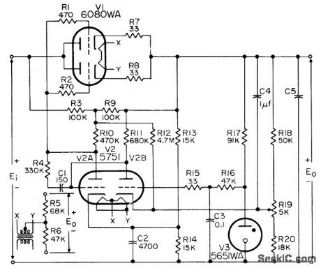
Provides either polarity of output with 1% regulation, from minimum of 350 v d-c input. Maximum output current is 125 ma for single series tube section and 100 ma per triode section when two or morn are paralleled. Minimum value of C5 is 4 mfd.-NBS, Hand-book Preferred Circuits Navy Aeronautical Electronic Equipment, Vol. 1, Electron Tube Circuits, 1963, PC 3, p 3-2. (View)
View full Circuit Diagram | Comments | Reading(1018)
Negative_voltage_regulator_using_an_ECG923_or_ECG923D_precision_regulator_IC
Published:2009/7/20 6:06:00 Author:Jessie
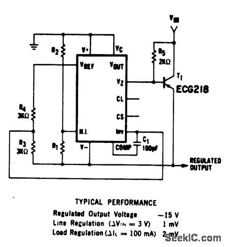
Negative voltage regulator (15 volts) using an ECG923 or ECG923D precision regulator IC. For metal can applications, where Vz is required, an external 6.2-volt zener should be connected in series with the regulated output. R1 is 3.65 ohms and R2 is 11.5 ohms for a ±5% fixed output (courtesy GTE Sylvania Incorporated). (View)
View full Circuit Diagram | Comments | Reading(872)
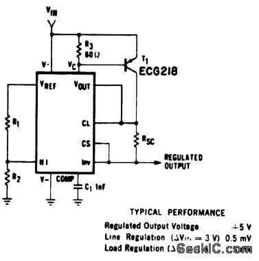
Short_circuit_protected_current_boost_regulator_using_the_ECG9XX_series_of_regulators
Published:2009/7/20 6:05:00 Author:Jessie
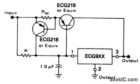
Short-circuit protected current boost regulator using the ECG9XX series of regulators.The ratings of the ECG9XX series are as follows: ECG960, 5 volts; ECG962, 6 volts; ECG966, 12 volts; ECG968, 15 volts; and ECG972, 24 volts. The current-sensing ECG2:8 transistor must be able to handle the current of the three-terminal regulator; therefore, a 4-ampere transistor is specified. Resistor R in conjunction with the VBE of the pass transistor determines when the transistor begins to conduct. Input-output differential voltage minimum is increased by the VBE of the pass transistor (courtesy GTE Sylvania Incorporated). (View)
View full Circuit Diagram | Comments | Reading(1290)
BLOCKING_OSCILLATOR_SWITCHING_VOLT_AGE_REGULATOR
Published:2009/7/20 6:05:00 Author:Jessie
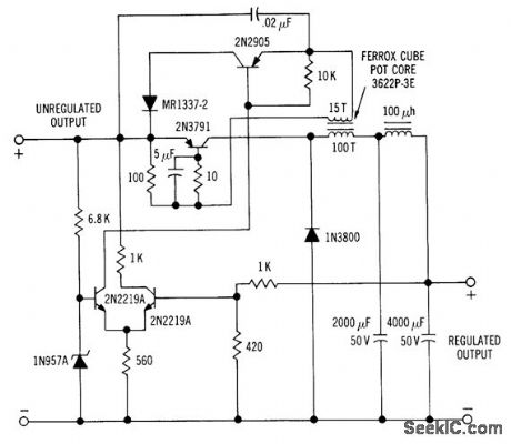
Efficiency is improved greatly by having current of 2N379l transistor flow through load. Differential-amplifier voltage-sensing arrangement controls ac lion of oscillator to maintain constant output voltage. Will regulate 24.v output lo within 1% over load range of 100 ma to 2 amp. Oscillator frequency is 6 kc.-H. Weber, Two Unique Switching Voltage Regulators Using Blocking Oscillators, Motorola Application Note AN-163, Aug. 1965. (View)
View full Circuit Diagram | Comments | Reading(837)
Current_regulator_using_the_ECG9XX_series_of_fixed_voltage_regulators
Published:2009/7/20 6:04:00 Author:Jessie
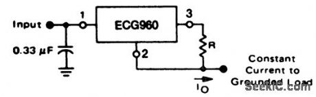
Current regulator using the ECG9XX series of fixed voltage regulators. The series and ratings are as follows: ECG960, 5.0 volts; ECG962, 6.0 volts; ECG966, 12 volts: ECG968, 15volts; and ECG972, 24 volts. It is recommended that the regulator input be bypassed if the regulator is at a distance from the power supply filters. A 0.33 μF or larger tantalum or Mylar should be used. If an aluminum type is used it should be 1.0 pF or larger. Using the 5-volt ECG960 as an example, resistor R determines the current as follows: Io = (5 volts/R) + IQ, where IQ is 1.5 mA over line and load changes (courtesy GTE Sylvania Incorporated). (View)
View full Circuit Diagram | Comments | Reading(662)
SIMPLE_5_VOLTAGE_SUPPLY
Published:2009/7/20 5:53:00 Author:Jessie

Provides -6 v and both positive and negative 12 and 18 v outputs, each regulated by zeners, for linear integrated-circuit tester and for integrated circuits under lest. Transformer has cenfertapped 24-v secondary. Lamp across half of secondary operates at 12 v to extend life.-J. N. Giles, How to Measure Linear-IC Performance, EEE, 14:8, p 62-68 and 161. (View)
View full Circuit Diagram | Comments | Reading(632)
REFERENCE_AMPLIFIER_12_V_REGULATED_SUPPLY
Published:2009/7/20 5:52:00 Author:Jessie
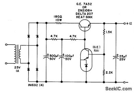
Uses integrated device consisting of zener diode and npn transistor in single pellet, to serve dual function of voltage reference element and error voltage amplifier. Provides up to 100 ma. 180-ohm series resistor provides short-circuit protection by limiting output current to less than 200 ma. Output regulation is better than 0.3% for line voltage variations of 10%.- Trcmsistor Manual, Seventh Edition, General Electric Co., 1964, p 231. (View)
View full Circuit Diagram | Comments | Reading(638)
Tracking_positive_and_negative_voltage_reference_using_an_ECG947_dual_operational_amplifier
Published:2009/7/20 5:51:00 Author:Jessie
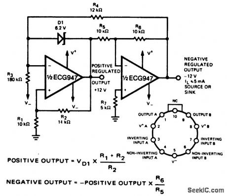
Tracking positive and negative voltage reference using an ECG947 dual operational amplifier. The ECG947 is short-circuit protected and requires no external components for frequency compensation (courtesy GTE Sylvania Incorporated). (View)
View full Circuit Diagram | Comments | Reading(739)
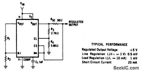
Positive_precision_voltage_regulator_using_an_ECG915_or_ECG915D_IC
Published:2009/7/20 5:50:00 Author:Jessie
Positive precision voltage regulator (5 volts) using an ECG915 or ECG915D IC. For a ±5% fixed output R1 is 2.15 ohms, R2 is 4.99 ohms and Rsc is 10 ohms (courtesy GTE Sylvania Incorporated). (View)
View full Circuit Diagram | Comments | Reading(604)
_Current_boost_regulator_for_5_amperes_using_the_ECG9XX_series_of_
Published:2009/7/20 5:49:00 Author:Jessie
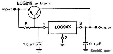
Current boost regulator for 5 amperes using the ECG9XX series of regulators. The ratings of the ECG9XX series are as follows:ECG960,5 volts;ECG962,6 volts;ECG966,12 volts;ECG968,15 volts; and ECG972,24 volts. Resistor determines when the transistor begins to conduct. This circuit is not short-circuit proof. Input-output differential voltage minimum is increased by the VBE of the transistor (courtesy GTE Sylvania Incorporated). (View)
View full Circuit Diagram | Comments | Reading(1029)
| Pages:121/291 At 20121122123124125126127128129130131132133134135136137138139140Under 20 |
Circuit Categories
power supply circuit
Amplifier Circuit
Basic Circuit
LED and Light Circuit
Sensor Circuit
Signal Processing
Electrical Equipment Circuit
Control Circuit
Remote Control Circuit
A/D-D/A Converter Circuit
Audio Circuit
Measuring and Test Circuit
Communication Circuit
Computer-Related Circuit
555 Circuit
Automotive Circuit
Repairing Circuit