
power supply circuit
Index 111
RANDOM_NOISE_GENERATOR
Published:2009/7/17 22:05:00 Author:Jessie
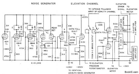
Uses thyratron in magnetic field as basic noise source, to provide azimuth and elevation drive signals for missile radar that simulale actual tracking conditions. Eliminates need for expensive test drones in evaluating missile performance. –C. E. Hendrix, Target Simulator Tests Beam-Rider Missiles, Electronics, 31:5, p 32-35. (View)
View full Circuit Diagram | Comments | Reading(1487)
25_TO_450_MC_NOISE_GENERATOR
Published:2009/7/17 22:04:00 Author:Jessie
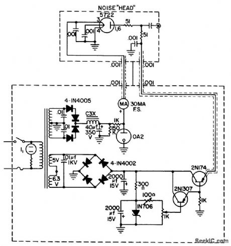
Uses conventional noise diode in shielded head. Transistor series regulator with zener diode improves performance when making noise figure measurements of communications receivers.-H. Olson and H. Howard, Noise Figure Measurement Fundamentals, Electronic Technician, November 1965, p 63-66 and 108. (View)
View full Circuit Diagram | Comments | Reading(924)
G_M_COUNTING_RATE_METER
Published:2009/7/19 21:42:00 Author:Jessie
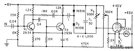
Uses Two transistors in integrating circuit and pentode recorder drive. Output of counting-rate mvbr Q1-Q2 is 4.5-V, 260.microsec square pulse that charges integrating capacitor C1 through D2.-F. E. Armstrong and E. A. Pavelka, Monitoring Radioisotope Tracers in Industry, Electronics, 32:26, p 42-43. (View)
View full Circuit Diagram | Comments | Reading(639)
Measuring_ratiometric_values_of_quad_load_cells
Published:2009/7/19 21:42:00 Author:Jessie
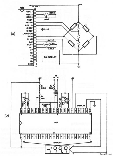
This circuit shows an ICL7107 connected to measure ratiometric values of quad load cells, and to display the results on a 31/2-digit LED. Direct connections between the ICL7107 and the LED are shown in Fig. 12-10B. The resistor values with the load-cell bridge are determined by the desired sensitivity. (View)
View full Circuit Diagram | Comments | Reading(2635)
G_M_COUNTER_AND_IONIZATION_GAGE
Published:2009/7/19 21:41:00 Author:Jessie

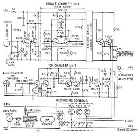
Used to correlate cosmic radiation intensity with other ionospheric and geomagnetic phenomenom. G-M counter provides negative pulse that is differentiated, shaped, and amplified in circuits similar to that of ion chamber. Counter rate is scaled down by 9-stage binary sealer before square wave output is fed to telemetering unit.-L. E. Peter-son R. L. Howard, and J. R. Winckler, Bal-loon Gas Monitors Cosmic Radiation, Electronits, 31:45, p 76-79. (View)
View full Circuit Diagram | Comments | Reading(1524)
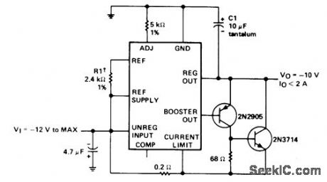
_10V_AT_1A
Published:2009/7/19 21:41:00 Author:Jessie
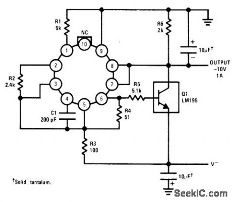
National LM195 power transistor, used with LM105 regulator, provides full overload protection. Load regulation is better than 2 mV. Circuit requires only 2-V differential between input and output voltages.-R. Dob-kin, Fast IC Power Transistor with Thermal Protection, National Semiconductor, Santa Clara, CA, 1974, AN-110, p 5. (View)
View full Circuit Diagram | Comments | Reading(886)
Electronic_music_synthesizer
Published:2009/7/19 21:41:00 Author:Jessie
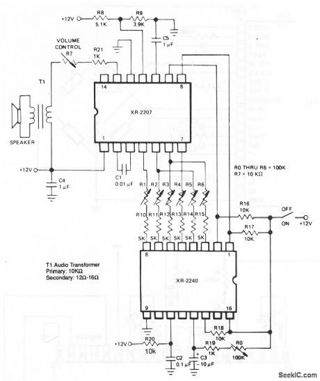
In this circuit, the XR-2207 oscillator produces a sequence of tones by oscillating at a frequency set by C1 and resistors R1 through R6 (which sot the frequency or pitch of the output tone sequence). The XR-2240 counter/timer generates pseudo-random pulse patterns by selectively counting down the time-base frequency. The outputs of XR-2240 (pins 1 through 8) activate the timing resistors R1 through R6 of XR-2207, which convert the binary pulse patterns to tones. C3 and R0 set the beat or tempo of the music. The output tone sequence continues for about 1 to 2 minutes (depending on the beat ) and then repeats. The XR-2240 resets to zero when power is applied, so the tone sequence (or music) always starts from the same point when the synthesizer is turned on. (View)
View full Circuit Diagram | Comments | Reading(1696)
Precision_electronic_thermometer
Published:2009/7/19 21:38:00 Author:Jessie


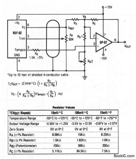
This circuit shows how a voltage reference can be combined with an op amp to create an electronic thermometer (with±5% accuracy). To calibrate, measure the voltage at pin 3 of REF-02, and the ambient room temperature (TA in℃). Then find X as follows:
selected from table in Fig. 12-8. Then, turn off the power, short pin 6 (VO) of REF-02 to ground, apply exactly 100.00 mV to the op-amp output (pin 6 of OP-07), and adjust RB2 so that VB= X. Now, remove the short and the 100-mV source, reapply circuit power, and adjust RP so that the op-amp output voltage equals (TA) (,S). The system is now calibrated. For remote sensor applications, a 1.5-kΩ resistor (RS) must be connected in series with pin 6 of REF-02. This isolates REF-02 from cable capacitances. Use low temperature coefficient metal-film resistors for RA, RB, and RC Raytheon Linear integrated Circuits, 1989 p. 8-16 (View)
View full Circuit Diagram | Comments | Reading(790)
FOLDBACK_CURRENT_LIMITING
Published:2009/7/19 21:38:00 Author:Jessie
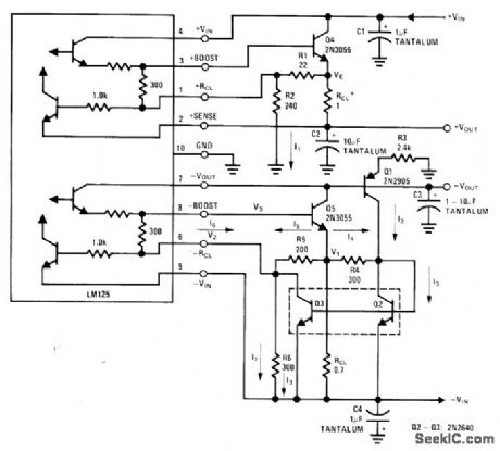
Reduces short-circuit output current of National LM125 dual tracking regulator sections to fraction of full-load output current, avoiding need for larger heatsink. Programmable current source is used to give constant voltage drop across R5 for negative regulator. Simple resistor divider serves same purpose for positive regulator. Design examples are given.-T. Smathers and N. Sevastopoulos, LM125/LM126/LM127 Precision Dual Tracking Regulators, National Semi-conductor, Santa Clara, CA, 1974, AN-82, p7. (View)
View full Circuit Diagram | Comments | Reading(1293)
MECHANICAL_COUNTER_DRIVE
Published:2009/7/19 21:37:00 Author:Jessie

Takes output from scale-of-64 circuit and converts to 40-millisec square-wave pulse by means of complementary mvbr, to drive coil of mechanical register, once for every 64 pulses from G –M tube,-F, E. Armstrong, Battery Powered Portable scaler Electronic, 33:19 74-75. (View)
View full Circuit Diagram | Comments | Reading(643)
±15V_TRACKING
Published:2009/7/19 21:36:00 Author:Jessie

Single NE/SE5554 dual tracking regulator is used with pass transistors to give higher output current than 200-mA limit for each section of regulator, with close-tolerance tracking.- Signetics Analog Data Manual, Signetics, Sunnyvale, CA, 1977, p 672-673. (View)
View full Circuit Diagram | Comments | Reading(1594)
_10V_AT_2A
Published:2009/7/19 21:35:00 Author:Jessie
Negative-voltage regulator using SN52104 or SN72304 accepts input voltage of -12V to -40V and uses only single external resistor to provide regulated output of -10 V with typical load regulation of 1mV and input regulation of 0.06%. ICs are interchange-able with LM104 and LM304 respectively.- The Linear and Interface Circuits Data Book for Design Engineers, Texas Instruments, Dallas, TX, 1973, p 5-5. (View)
View full Circuit Diagram | Comments | Reading(1888)
Voltage_to_frequency_converter_with_zero_and_full_scale_adjust
Published:2009/7/19 21:34:00 Author:Jessie
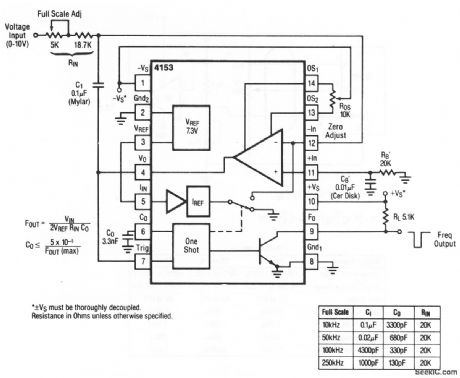
This circuit shows a VFC with both zero and full-scale adjustments.Raytheon Linear Integrated Circuits, 1989 p 7-20 (View)
View full Circuit Diagram | Comments | Reading(731)
Frequency_to_voltage_converter_with_zero_and_full_scale_adjust
Published:2009/7/19 21:32:00 Author:Jessie
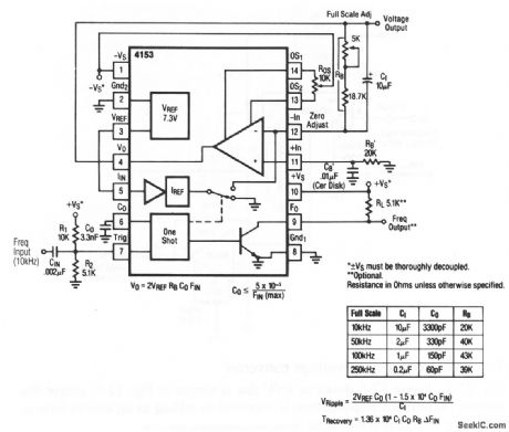
This circuit shows an FVC with both zero and full-scale adjustments.Raytheon Linear integrated Circuits 1989 p 7 19 (View)
View full Circuit Diagram | Comments | Reading(718)
0_25V_AT_0_10A
Published:2009/7/19 21:30:00 Author:Jessie
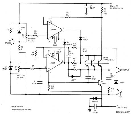
Lab-type constant-voltage/constant-current power supply using standard ICs achieves high current output by paralleling of seven LM395 power transistors serving as pass element. Current limiting is provided on LM395 chip for complete overload protection.- Linear Applications, Vol. 2, National Semiconductor, Santa Clara, CA, 1976, LB-28. (View)
View full Circuit Diagram | Comments | Reading(3148)
±15V_AT_7A
Published:2009/7/19 21:29:00 Author:Jessie
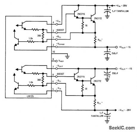
External Darlington stages boost output currents of LM125 dual tracking regulator and increase minimum input/output voltage differential to 4.5 V. Maximum output current is limited by power dissipation of 2N3772. Typical load regulation is 40 mV from no load to full load.-T. Smathers and N Sevastopoulos, LM125/LM126/LM127 Precision Dual Tracking Regulators, National Semiconductor, Santa Clara, CA, 1974, AN-82, p 6. (View)
View full Circuit Diagram | Comments | Reading(939)
5V_AT_20_A_AND_0_25V_AT_0_24_A
Published:2009/7/19 21:27:00 Author:Jessie
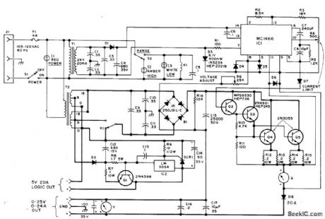
Developed as lab supply for experimenting with high-current TTL circuits. Motorola MC1466 monitors voltage and current requirements monitors voltage and current requirement continuously, providing output proportional to paramenters called for by front-panel controls of supply. D2 and D8 are 50-PIV 20-A diodes, and all other diodes except D3 are 1N4002 or are equivalent. Article give construction detail.- J. W. Crawford, The Smart Power Supply, 73 Magazine, March 1976, p 96-98 and 100-101. (View)
View full Circuit Diagram | Comments | Reading(3038)
Basic_frequency_to_voltage_converter
Published:2009/7/19 21:27:00 Author:Jessie
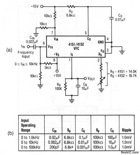
Figure 12-4A shows a stand-alone FVC. Figure 12-4B shows the operating range for various component values. This circuit performs the opposite of a VFC (the FVC converts an input pulse train into an average output voltage). Raytheon Linear Integrated Circuits 1989 p. 7-9. (View)
View full Circuit Diagram | Comments | Reading(1498)
MULTI_OUTPUT_BINARY
Published:2009/7/19 21:26:00 Author:Jessie
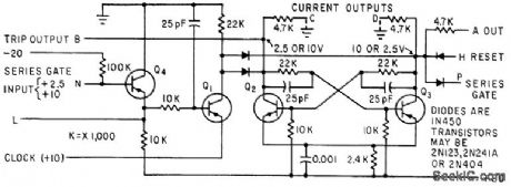
Basic binary circuit of 256-channel neutron analyzer is controlled by diode gates in coincidence with dock pulses derived from 200-kc crystal oscillator. Used in countdown, address overflow, memory cycle, sync, and gate stages.-E. J. Wade, Digital Instrumentation for Nuclear Research Tests, Electronics, 33:43, p 68-71. (View)
View full Circuit Diagram | Comments | Reading(725)
Precision_voltage_sourced_VFC
Published:2009/7/19 21:25:00 Author:Jessie
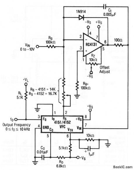
Figure 12-3 shows a voltage-sourced VFC that is similar to Fig. 12-2, except that current pulses into the integrator are taken directly from the switched voltage reference. This improves temperature drift at the expense of high-frequency linearity. Raytheon Linear Integrated Circuits, 1989, p 7-8 (View)
View full Circuit Diagram | Comments | Reading(681)
| Pages:111/291 At 20101102103104105106107108109110111112113114115116117118119120Under 20 |
Circuit Categories
power supply circuit
Amplifier Circuit
Basic Circuit
LED and Light Circuit
Sensor Circuit
Signal Processing
Electrical Equipment Circuit
Control Circuit
Remote Control Circuit
A/D-D/A Converter Circuit
Audio Circuit
Measuring and Test Circuit
Communication Circuit
Computer-Related Circuit
555 Circuit
Automotive Circuit
Repairing Circuit