
power supply circuit
Index 25
Low Riple Power Supply
Published:2013/3/20 1:28:00 Author:Ecco | Keyword: Low Riple, Power Supply
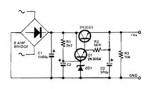
This Low riple power supply circuit can be used in which a high current is needed with a low ripple voltage (for example in a high powered class AB amplifier when high quality reproduction is required).
Q1, Q2, and R2 may be considered as a power darlington transistor. ZD1 and R1 give a reference voltage at the base of Q1. ZD1 should be selected thus: ZDl = Vow-1.2. C2 can be picked for the degree of smoothness as its value is effectively multiplied by the combined gains of Q1/Q2, if 100 µF is chosen for C2, assuming minimum hfe for Q l and Q2, C = 100 x 15(Q1) x 25(Q2) = 37,000 uF.
(View)
View full Circuit Diagram | Comments | Reading(997)
5V / 10A regulator circuit
Published:2013/3/20 1:27:00 Author:Ecco | Keyword: 5V / 10A regulator
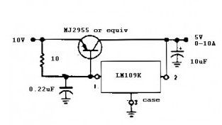
This power supply regulator circuit can provide current up to 10 amperes at a voltage 5 V.
The circuit is built from a complete 5V regulator IC LM 109 series from National Semiconductor. While for the current amplifier assisted by the PNP type transistor MJ 2955.
(View)
View full Circuit Diagram | Comments | Reading(1948)
5V / 3A Regulator
Published:2013/3/20 1:26:00 Author:Ecco | Keyword: 5V / 3A Regulator
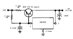
This regulator power supply schematic diagram is the same as the previous 5V 10A regulator circuit with a little modification and have the ability to supply less current up to 3 amperes at voltage of 5V.
The circuit is built from a complete 5V regulator IC LM 109 series from National Semiconductor. While for the current amplifier using a PNP type transistor MJE 370.
(View)
View full Circuit Diagram | Comments | Reading(1512)
5V / 4A Regulator Circuit
Published:2013/3/20 1:26:00 Author:Ecco | Keyword: 5V / 4A , Regulator
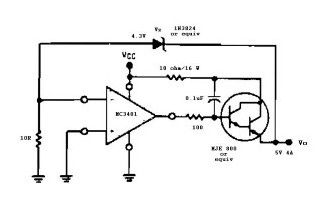
This is the other power supply regulator circuit, is different from the previous circuit, this using IC op amp quad type MC 3401 operational amplifier from Motorola. Here is also used NPN Epitaxial Silicon Darlington Transistor MJE 800.
(View)
View full Circuit Diagram | Comments | Reading(1486)
Linear Power Supply
Published:2013/3/20 1:24:00 Author:Ecco | Keyword: Linear Power Supply
Every electronic circuit will work as good as its power supply. However this is often overlooked. There are two main families of power supplies: the linear power supply and switch mode power supplies. Linear power supplies are easier to manufacture and to troubleshoot. But they have the disadvantage (especially for high power), the circuit is more complicated with the results of less power and heat faster than the switch mode power supply.
For a manufacturer, the choice of type of power supply will obviously influence the cost of manufacturing or integration. It should be notedthat anyhardwarevendordoes notmake themost ofits own power supply,and oftenwillbuy froma specialist.Creating aswitchingpower supplybyamateur is relatively difficult,evenwith the advent ofintegratedcomponentsprovidemost of the work.
In any case,strongly suggesta beginnerin electronics tostartwith the realization oflinearpower supply.Similarly,youare advisednottosolve theproblem ofswitchmodepowersupplyifyoudo notfullyunderstand.However, insome articlesthat this will bediscussed about thelinearpower supply.
(View)
View full Circuit Diagram | Comments | Reading(1330)
Low Power Regulated DC to DC Converter
Published:2013/3/20 1:24:00 Author:Ecco | Keyword: Low Power , Regulated DC to DC Converter
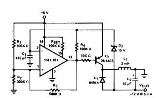
This Low power regulated dc to dc converter circuit obtained by adding a flyback circuit to a square wave oscilator.
This dc dc converter circuit operating at a frequency of 20 kHz to minimize the size of L1 and C2. Regulation is achieved by zener diode D2. Maximum current available before the converter drops out of regulation is 5.5 mA.
(View)
View full Circuit Diagram | Comments | Reading(789)
Lithium Battery Charger
Published:2013/3/20 1:22:00 Author:Ecco | Keyword: Lithium Battery Charger
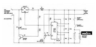
This Lithium batterychargercircuitis dedicatedto chargelithiumbatteries.Ituses 2chips, voltage regulatorLM317TandICL7665warnsmicroprocessors(μPs)ofovervoltageand undervoltageconditions.
Charging is completed with a constant current of 60 ma for Aa cells to a cutoff voltage of 2.4 V per cell, at which point the charge should be terminated. The charging system shown is made for multi-cell lithium battery packs of two to six series-connected cells or series/parallel arrangements. It is important that all of the cells built in the pack are at an identical state-of-charge (voltage) before charging. The maximum upper cut-off voltage is 15.6 V (6 x 2.6 V).
(View)
View full Circuit Diagram | Comments | Reading(0)
Low Voltage Regulators with Short Circuit Protection
Published:2013/3/20 1:22:00 Author:Ecco | Keyword: Low Voltage , Regulators, Short Circuit Protection
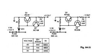
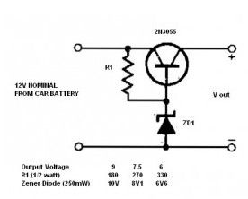
These Low Voltage regulators with short circuit protection can provide 6, 7.5, and 9 V from an automobile battery supply of 13.5 V nominal, however, they will function just as well if connected to a smoothed dc output from a transformer/rectifier circuit.
Two types are shown for both positive and negative ground systems. The power transistors can be mounted on the heatsink without a mica insulating spacer thus allowing for greater cooling efficiency. Both circuits are protected against overload or short-circuits. The current can’t exceed 330 mA. Under normal operating conditions the voltage across R2 does not rise above the 500 mV necessary to turn Q2 on and the circuit behaves as if there was only Q1 present. If excessive current is drawn, Q2 turns on and cuts off Q1, protecting the reg-ulating transistor. The table gives the values of R1 for different zener voltages.
(View)
View full Circuit Diagram | Comments | Reading(2073)
Variable Voltage Regulator based LM117
Published:2013/3/20 1:20:00 Author:Ecco | Keyword: Variable Voltage Regulator
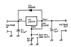


The regulator circuit uses an LM117K three-terminal adjustable output positive voltage regulator in a TO-3 can. The variable voltage regulator lets you adjust the output voltage of a fixed DC power supply between 1.2 and 37 VDC, and will supply the output current in excess of 1.5 A.
Thermal overload protection and short-circuit current-limiting constant with temperature are included in the package. Capacitor Cl reduces sensitivity to input line impedance, and C2 reduces excessive ringing. Diode CR1 prevents C2 from diseharoinu through the IC during an output short.
(View)
View full Circuit Diagram | Comments | Reading(1355)
Simple 12V to 9, 7.5 or 6V converter
Published:2013/3/20 1:19:00 Author:Ecco | Keyword: 12V to 9, 7.5 or 6V, converter
You’re traveling and you forgot to bring DC to DC converter in your car, but you need it. This simple DC to DC converter circuit can help you.
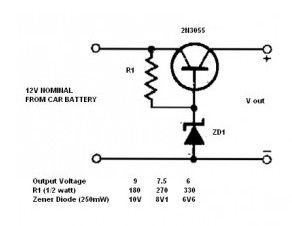
This DC to DC converter circuit enables transistorized items such as radio, cassettes, and other electrical devices to be operated from a car’s electrical supply. The table gives values for resistors and specified diode types for different voltage. Should more than one voltage be required a switching arrangement could be incorporated. For high currents, the transistor should be mounted on a heatsink.
(View)
View full Circuit Diagram | Comments | Reading(1804)
Positive Regulator with PNP Boost
Published:2013/3/20 1:17:00 Author:Ecco | Keyword: Positive Regulator , PNP Boost
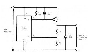
The IC8211 (Programmable Voltage Detectors) provides the voltage reference and regulator amplifier, while Q1 is the series pass transistor. R1 defines the output current of the IC8211, while Cl and C2 provide loop stability and also act to suppress feedthrough of input transients to the output supply.
(View)
View full Circuit Diagram | Comments | Reading(0)
Single Output Power Supply 12V / 5A based on LM338
Published:2013/3/20 1:14:00 Author:Ecco | Keyword: Single Output , Power Supply, 12V / 5A
You’re traveling and you forgot to bring DC to DC converter in your car, but you need it. This simple DC to DC converter circuit can help you.
(View)
View full Circuit Diagram | Comments | Reading(2965)
Single Output Power Supply +5V to +15 V / 1A based on LM78xx
Published:2013/3/20 1:13:00 Author:Ecco | Keyword: Single Output, Power Supply, +5V to +15 V , 1A
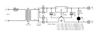
This power supply is very simple and suitable for the device either analog or digital type. Key Features of the power supply:Voltage: 5 V, 6 V, 8 V, 9 V, 12 V or 15 VCurrent: 1 ARegulated: Yes
This single output power supply circuit uses a voltage regulator which is quite famous LM78xx fixed type. Output voltage of 5 V here, but the adoption of other values from +5 V to +15 V is very possible, with the changes described in the image above. The current that can be drawn from this supply is directly related to the type of regulator used here and is limited to 1 A, and therefore provided to add a heatsink for cooling. This power is required even if you do not need 1 A; current supplied by power supply depending on the needs of the device. If we connect the device consumes 100 mA current at the power source capable of providing a value of 1 A, it will only provide 100 mA.
Before starting assembly, it is useful to describe two or three things about your power supply. This type of regulator used in theory can provide a maximum current 1.5 A. Under such currents, the controller gets a lot of heat, and are in thermal protection if it is too hot (it turns itself off to protect itself, and released when the temperature has returned correctly). Heating controller depends on two factors: the potential difference between the input and output, and the current passing through it (which is what will cost you). If the potential difference is important, you can not make a lot of power to the controller. At the same time, the controller must have input voltage of 3 V above the output voltage (for +5 V regulated output, the input voltage must be at least 8 V). Knowing that the voltage regulator receives input as high as 37V, you will discover what makes sense between the two limits, depending on the desired output current. For the summarize, if you want to get high current (say, 1 A), you should not apply overload input voltage (say it will be limited to 10 V. V 0.12 to 5 V output). To be able to work the regulator in the power range incurred, it is very important to provide cooling heatsink.
(View)
View full Circuit Diagram | Comments | Reading(864)
Bipolar +/- 15V and 5V from Car Battery supply
Published:2013/3/20 1:11:00 Author:Ecco | Keyword: Bipolar, +/- 15V , 5V , Car Battery supply
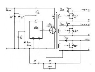
This DC to DC Converter use Max 541 from Maxim, IC1 is a switching regulator that generates a 45-kHz signal that drives the gate of MOSFET Q1 BUZ71A from Motorolla. The sourceofthispower supplycomes froma 12Vcarbattery voltage. This DCtoDCconverter have an output +-15Vand5V.
D1, D2, and D3 are Schottky diodes. The 5 V output is sensed as a reference; feedback to the chip turns off the gate signal to Q1 if the voltage rises above 5 V.
T1 has Trifilar windings that assume about 2% regulation for a 10-to 100-mA load change on the ± 15-V supplies. R1/D4 provide overvoltage protection. T1 has a primary inductance of about 21 H. Core size should allow 4 A peak currents. The turn ratios are 111/2 turns each for the 15-V supplies, 111/2 turns for the primary, and four turns for the 5 V secondary. The efficiency is about 75%.
(View)
View full Circuit Diagram | Comments | Reading(1060)
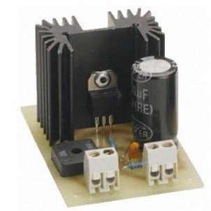
Adjustable Regulated Power Supply 0-15V / 1A
Published:2013/3/18 22:11:00 Author:Ecco | Keyword: Adjustable, Regulated Power Supply , 0-15V, 1A
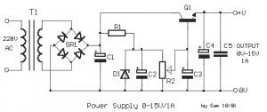
This is the schematic diagram of adjustable power supply which the voltage output can be vary from 0V up to 15V with fixed current output maximum of 1A. The circuit is very simple and easy to build, finding the components is easy and inexpensive. The output voltage is stabilized and regulated in the range of 0V to +15 V, supplied with a maximum current of 1 A.The potensiometer R2 is used to adjust the voltage output. The Q1 is an old type power transistor which commonly used to amplify an input, and this transistor needs to be on heatsinks, as it will be heat up when working continuously in the region of maximum current. The type of transformer is standard on the market. (View)
View full Circuit Diagram | Comments | Reading(1230)
Choosing a PC Power Supply by Power Comparison
Published:2013/3/18 22:09:00 Author:Ecco | Keyword: PC Power Supply, Power Comparison
Power supply is probably the most computer components are often overlooked by PCs buyers. However, this component is very important : such as when the power is insufficient or if the voltage is too unstable, the power supply can cause crashes or reboots the machine. Even worse, if power is working too hard and / or in poor quality, maybe just by turning on the computer may cause damage to most of the components: motherboard, CPU, hard drive and a DVD player! Note that branded manufacturers are also found in the market often overlook the power supply in order to reduce the selling price of the computer. Most buyers assume the power supply is not important, some unscrupulous manufacturers introduce large-sized power and poor quality for their machines.
(View)
View full Circuit Diagram | Comments | Reading(911)
Single Output Power Supply +1.25 V to 28 V / 1A Based on LM317
Published:2013/3/18 22:08:00 Author:Ecco | Keyword: Single Output, Power Supply , +1.25 V to 28 V / 1A
The voltage regulator used here (LM317) theoretically can provide 1A maximum current. Its heating depends on two factors: the potential difference between its input and output, and the current passing through it (which is what the charge will apply). If the potential difference is important, you can not make out much power to the controller. At the same time, the controller must have its input voltage of at least 3 volts higher than the output voltage (for 12V regulated output, the input voltage must be at least 15V). Knowing that the regulator accepts a voltage as high as 37V input, you will find what is reasonable between these two limits, depending on the desired current output. In summary, avoid using an input voltage too high for a low output voltage if you really do charge to 1A power supply, limit yourself to 5V or 6V differential. In order to to work the regulator in the power range for which it is said, it is imperative to provide a sufficiently large cooling radiator.
(View)
View full Circuit Diagram | Comments | Reading(978)
Car DC to DC Converter for laptops
Published:2013/3/18 22:07:00 Author:Ecco | Keyword: Car , DC to DC, Converter, laptops
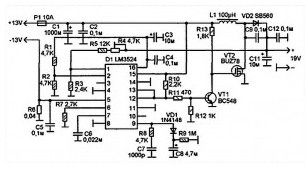
Laptops today are the what is called notebook computers, which now is becoming popular. Laptops can be brought into the bag making it suitable for business trips. And even as the “home entertainment center” laptop is more convenient, because it takes a little space. However, in my opinion, there is one very important which become shortcomings – most laptops which powered by an electric voltage of 19V, making it impossible for them to direct the power to an integrated network vehicle (12-14V). It is very important, especially when laptop battery capacity is not more than two hours in active mode. And what if you, at some object in the whole day want to process some data, but no other useful sources of electricity?
This is a description of the relatively simple psu laptop circuit adapter (laptop DC-DC converter), which increases the voltage-board vehicle network to 19V, needed to supply the laptop. And maintain this voltage stable.
The adapter is based on chip LM3524, which is a high-frequency switching DC-DC converter with pumped inductance and output current up to 200mA, the output current which, in this scheme, will increased to 3.5-4A using a powerful transistor switch (on transistors VT1 and VT2).
(View)
View full Circuit Diagram | Comments | Reading(1118)
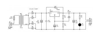
5000VDC Output from 230 VAC Input, with Diode Voltage Multiplier / Capacitor
Published:2013/3/18 22:07:00 Author:Ecco | Keyword: 5000VDC Output, 230 VAC Input, Diode Voltage Multiplier , Capacitor
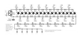
The diagram shows a set of cell diode / capacitor connected in series, each set of increasing voltage 300 V.The voltage 230 V applied to the input of voltage multiplier, it gradually increased in each set of diodes / capacitors. Which eventually reached a value of more than 5000 V at the anode of the last diode (D16). Voltage rise gradually, as the capacitor discharged at the time of power up: voltage 5000 V was obtained after a few seconds.
(View)
View full Circuit Diagram | Comments | Reading(2335)
Dual Polarity Power Supply +/- 15V based Transistors
Published:2013/3/18 22:06:00 Author:Ecco | Keyword: Dual Polarity , Power Supply, +/- 15V , Transistors
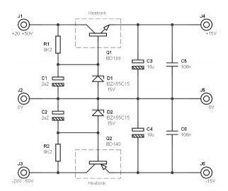
This Dual supply circuit is suitable for installation of power analog (audio or measurement), it provides a bipolar voltage with voltage source between 20 and 50 V (in audio power amp, for example). Regulated output voltage is 15V, but can be adjusted from + /-12V or + /-18V by simply changing two components. The maximum output current must not exceed 100 mA each branch.
If you ask, where the transformer and diode rectifier?This circuit is intended to be transplanted into an existing circuit (eg audio amp), which already provides symmetric voltage between + /-20V and + /-50V.
(View)
View full Circuit Diagram | Comments | Reading(1866)
| Pages:25/291 At 202122232425262728293031323334353637383940Under 20 |
Circuit Categories
power supply circuit
Amplifier Circuit
Basic Circuit
LED and Light Circuit
Sensor Circuit
Signal Processing
Electrical Equipment Circuit
Control Circuit
Remote Control Circuit
A/D-D/A Converter Circuit
Audio Circuit
Measuring and Test Circuit
Communication Circuit
Computer-Related Circuit
555 Circuit
Automotive Circuit
Repairing Circuit