
power supply circuit
Index 21
5V FET Voltage Regulator circuit
Published:2013/3/29 4:35:00 Author:Ecco | Keyword: 5V FET Voltage Regulator
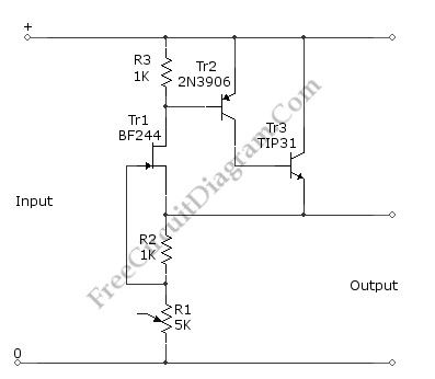
This voltage regulator circuit gives a stable 5V output from unregulated inputs (more than 5V). The stability of the output voltage is good enough, only change less than 0.1 volts when the load current changes about 60mA. Here is the schematic diagram of the circuit:
(View)
View full Circuit Diagram | Comments | Reading(1709)
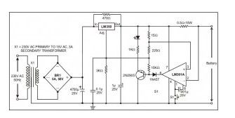
The Ni-Cad Battery Zapper, A Rechargeable Battery Reconditioner
Published:2013/3/28 3:52:00 Author:Ecco | Keyword: Ni-Cad Battery, Zapper, A Rechargeable Battery, Reconditioner
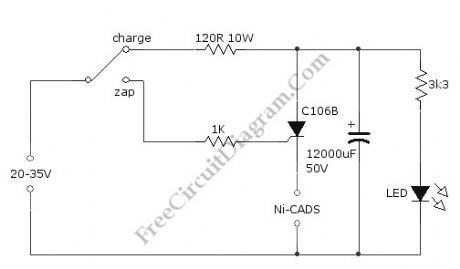
Ni-Cad (NiCd, NiCad) battery, sometimes doesn’t work as expected, gives no power and cannot be recharged. In this situation, the battery need to be reconditioned. It’ is possible that the battery is internally shorted, and we can get the battery into life again by recondition the Ni-Cad battery using a zapper circuit. This circuit restore the Ni-Cad battery from shorting by forcing a high current flow to burn the internal dirt. The current stored in the high capacitance capacitor is heavy discharged by the SCR when zapping, and the SCR is used to disconnect the battery connection when charging the capacitor. A 120 ohm 10W resistor is used to limit the current when charging the capacitor, and you have to make sure the LED’s intensity has reach the steady state before switching to zap position. After zapping the battery and switch to charge position, the charging process will take some period and indicated by the LED which will gradually increase the brightness until get stable intensity when fully charged. The power supply for this circuit can be taken from small transformer (350 mA to 1 A) with half or full wave rectifier. Here is the schematic diagram of the battery zapper circuit:
(View)
View full Circuit Diagram | Comments | Reading(3114)
The TLC497CN Negative Supply Generator
Published:2013/3/28 3:47:00 Author:Ecco | Keyword: Negative Supply Generator
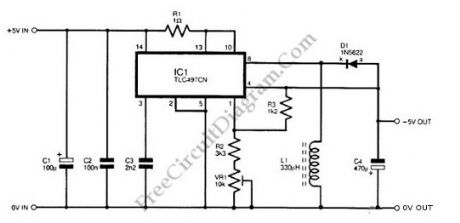
Negative supply from positive supply is needed if the circuit need both positive and negative supply while we have only positive supply. The circuit shown in the schematic diagram below is a negative supply generator, built using a TLC497CN integrated circuit. The TLC497CN is used as the main switching circuit, and it can provide negative supply of up to 150mA. With an input supply of 10V, this circuit has efficiency about 50% but it is decreased under 50% when the input voltage is 5V. This circuit use resistor R1 to protect the IC1 from damage by limiting the current at the input to IC1 because this circuit is often be fed from high current supply. To control the average output voltage, TLC497CN uses a variable clock frequency and a fixed pulse width. The timing component in the oscillator section of the PWM this circuit is capacitor C3. capacitors C2 and C1 are supply-decoupling components on the input supply.
(View)
View full Circuit Diagram | Comments | Reading(1153)
Industrial Battery Charger Project Kit
Published:2013/3/27 4:23:00 Author:Ecco | Keyword: Industrial, Battery Charger, Project Kit
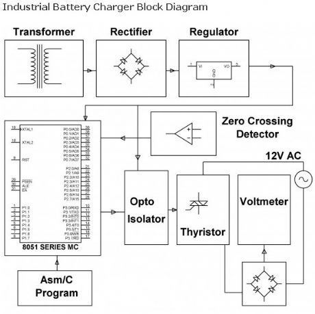
The assignment is intended for charging battery(s) by DC from AC supply of power. DC power supplied for a battery’s charger is a derivative from a thyristor controlled rectifier mechanism. AC supply of power is useful to a link rectifier consisting of diodes and a TRIAC achieving preferred power from the micro controller.
(View)
View full Circuit Diagram | Comments | Reading(1790)
Simple 12 Volt Battery charger
Published:2013/3/22 4:02:00 Author:Ecco | Keyword: 12 Volt Battery charger
This kind of battery charger circuit will quickly and easily recharge almost every lead acid battery pack.This battery charger supplies maximum current till the current drawn by the battery falls to 150 miliamper. At this point, less voltage will be applied to complete and avoid over charging. Once the lead acid battery is completely charged, this circuit goes off and lights up the led, showing that the battery has completed to be charged.
(View)
View full Circuit Diagram | Comments | Reading(2978)
12V to 220V 100W Inverter
Published:2013/3/22 4:01:00 Author:Ecco | Keyword: 100W Inverter
If we want to work with the electrical equipment outsite home that has a voltage 220Volt /AC 50HZ, that only have around 100Watt not exceed. Yo need Small power inverter around 100Watt. This inverter perform modify from work electrical power forces of electric battery 12 volt provide high voltage to work.
(View)
View full Circuit Diagram | Comments | Reading(2786)
Mobile Charger with Voltage Converter
Published:2013/3/22 4:00:00 Author:Ecco | Keyword: Mobile Charger , Voltage Converter
The circuit allows a simple and safe charging of 1-10 Ni-Cd or Ni-MH cells from a 12V source. The voltage converter can be operated at 6V, in this case is the max. output voltage 12V (no load). The performance can be improved through the use of Schottky diodes (D2/D3). D4 (LED) can omitted if you dont want any indicator. An astable Mutivibrator generates the oscillation frequency. At the output (pin 3) connected the voltage doubler. At C5 is idling roughly double the input voltage. Thus, sufficient voltage difference exists to charge the connected batteries.Due to the high Switching frequency can be used relatively small capacitors. The charge current is indicated by a “real” load control (D4).
(View)
View full Circuit Diagram | Comments | Reading(1787)
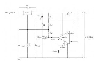
+15 Volt 1 Amp Regulated Power Supply
Published:2013/3/22 3:59:00 Author:Ecco | Keyword: +15 Volt, 1 Amp, Regulated Power Supply
The actual supply takes +20 Volt Dc through the dioda bridge or filter part. This can be given to pins 11 and 12 on ua723, and also for the collector 2N3055 series-pass transistor. All the output voltage will be sampled through R1 and R2, giving around 7 Volt relating to ground at pin 4. The reference terminal at pin 6 is linked right to pin 5, the noninverting input of the error amplifier.
(View)
View full Circuit Diagram | Comments | Reading(1491)
-15 V 1-A Regulated Power Supply
Published:2013/3/22 3:59:00 Author:Ecco | Keyword: -15 V, 1-A , Regulated Power Supply
The actual supply should get -20 V coming from rectifier/filter that is given to the collector of Darlington PNP-type pass transistor, a TIP 105. The base drive for the TIP105 is supplied via resistor R5. The base of the TIP is driven from Vz terminal at pin 9, this is anode of 6.2 V zener diode which links with the emitter of uA 723 output control transistor. The way of providing the positive feedback needed for feedback action is shown.
(View)
View full Circuit Diagram | Comments | Reading(0)
12 Volt Battery charger
Published:2013/3/22 3:58:00 Author:Ecco | Keyword: 12 Volt, Battery charger
The following schematic is a high-performance battery charger for gelled electrolyte lead acid battery. Battery charger quickly recharges lead acid battery and shuts off at a full charge. Innitially, charging current has limitations to 2 Ampere. While the battery voltage goes up, current to the lead acid battery decrease, and if the current has decrease to 150 mA, the battery charger changes to a lower float voltage protecting against overcharge.
(View)
View full Circuit Diagram | Comments | Reading(1870)
12 VDC TO 117 VAC / 60HZ POWER INVERTER
Published:2013/3/22 3:57:00 Author:Ecco | Keyword: 12 VDC TO 117 VAC , 60HZ , POWER INVERTER
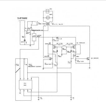
Capacitor C5 and potentiometer R12 figure out the frequency of the output signal at pin number 3 of IC1, the 555oscillator. The output signal is differentiated by C3 and C4 before it’s input to the base of powertransistors Q1 and Q2 through diodes D1 and D2, respectively. The signal from IC1 is adjusted to 120 Hertz,because the flip-flop created by transistors Q3 and Q4 splits the frequency by two.
(View)
View full Circuit Diagram | Comments | Reading(1473)
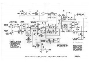
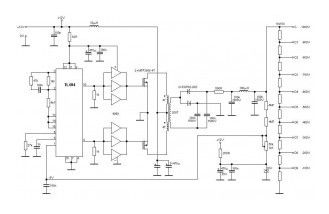
230W Switching Power Supply
Published:2013/3/22 3:56:00 Author:Ecco | Keyword: 230W, Switching Power Supply
View full Circuit Diagram | Comments | Reading(1874)
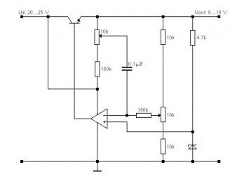
DC to DC Converter 12 Volt to 21 Volt
Published:2013/3/22 3:55:00 Author:Ecco | Keyword: DC to DC Converter, 12 Volt to 21 Volt
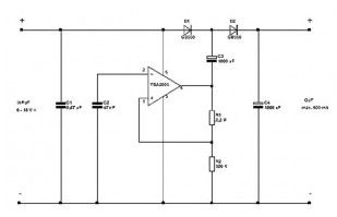
This 12 V to 21 V DC to DC Converter can perform nicely at 500mA maximum current. In case the current exceeds 500 milli-amperes, the voltage will drop below 21 Volt.
(View)
View full Circuit Diagram | Comments | Reading(2172)
Super-Clean 9VDC Power Supply Circuit
Published:2013/3/22 3:54:00 Author:Ecco | Keyword: Super-Clean, 9VDC, Power Supply
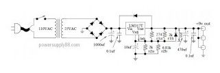
This circuit will give you a 9V regulated DC voltage at maximum current of about 1A. The circuit uses stepdown tansformer with secondary output voltage of 25V AC and 1A current. The primary voltage depended your home electrical power line installation. If your power line voltage is 110V then you must find transformer 110V primary voltage. The diode can be 4 pieces of 1N4002 (1A rectifier diode) or a 1A bridge diode.
(View)
View full Circuit Diagram | Comments | Reading(1440)
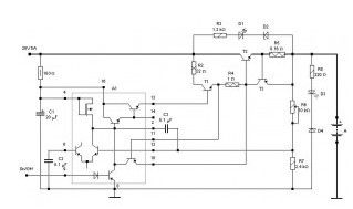
PWM Rectifier – power controller
Published:2013/3/22 3:52:00 Author:Ecco | Keyword: PWM Rectifier , power controller
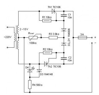
PWM Rectifier – power controller designed for low-voltage sources. Full-wave rectifier is made on the thyristors Th1, Th2, and power in the load from 0 to 40 W resistor regulate Rvar.
(View)
View full Circuit Diagram | Comments | Reading(2105)
10V High-Stability Voltage Source Model
Published:2013/3/22 3:52:00 Author:Ecco | Keyword: 10V , High-Stability, Voltage Source Model
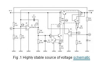
Experimental studies of exemplary scheme of a highly stable source of voltage (Fig. 1) in the temperature range from -18 ° C to 50 ° C show that the temperature error of less than ± 0.001% / ° C, temporal drift no more than ± 0.005% per day. Source has a small thermal hysteresis (Fig. 2).
(View)
View full Circuit Diagram | Comments | Reading(1175)
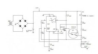
220 watts Uninterruptible Power Supply
Published:2013/3/22 3:50:00 Author:Ecco | Keyword: 220 watts , Uninterruptible Power Supply
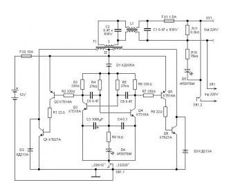
Uninterruptible power supply provides output power to 220 watts (load current up to 1A). In the mode switch SB1 12/220 – the battery voltage is applied to a given multivibrator Q3 Q4 50 Hz, which builds up powerful keys Q1, Q6, amplified and fed to transformer T1. With the secondary winding T1 voltage of 220 V and 50 Hz filters L1 C1 C2 goes to the load.
(View)
View full Circuit Diagram | Comments | Reading(1715)
Voltage regulator with zero ripple
Published:2013/3/22 3:49:00 Author:Ecco | Keyword: Voltage regulator , zero ripple
This voltage regulator input need around 20 Volt to 25 Volt. The voltage regulator with zero ripple voltage regulator with zero fluctuations is the usual parametric stabilizer, but the inverting input of op amp is fed from the potentiometer 10 k of the voltage ripple. These voltages are summed in opposite phase. 10K potentiometer can be adjusted compensation ripple at the output of the stabilizer, to virtually zero.
(View)
View full Circuit Diagram | Comments | Reading(1464)
Stable Power Supply for High Voltage -100V to -1000V
Published:2013/3/22 3:48:00 Author:Ecco | Keyword: Stable Power Supply , High Voltage , -100V to -1000V
Stable power supply for high voltage power supply for the core of a high voltage of the PWM – Controller TL494, loaded with over 4050 followers on a pair of powerful field-effect transistors, switching the primary winding of step-up transformer (4 + 4 turns – the primary winding, 200 turns – the secondary winding). With the secondary winding through a rectifier with voltage doubling and smoothing filter RC LC voltage reaches the voltage divider, and the regulator output voltage. Scheme can be used as a voltage converter to power the photomultiplier.
(View)
View full Circuit Diagram | Comments | Reading(2406)
5 A Stable Car Baterry Charger
Published:2013/3/22 3:39:00 Author:Ecco | Keyword: 5 A , Stable Car Baterry Charger
View full Circuit Diagram | Comments | Reading(2510)
| Pages:21/291 At 202122232425262728293031323334353637383940Under 20 |
Circuit Categories
power supply circuit
Amplifier Circuit
Basic Circuit
LED and Light Circuit
Sensor Circuit
Signal Processing
Electrical Equipment Circuit
Control Circuit
Remote Control Circuit
A/D-D/A Converter Circuit
Audio Circuit
Measuring and Test Circuit
Communication Circuit
Computer-Related Circuit
555 Circuit
Automotive Circuit
Repairing Circuit