
power supply circuit
Index 39
12-VOLT GEL CELL CHARGER
Published:2012/11/8 1:08:00 Author:muriel | Keyword: 12-VOLT, GEL CELL CHARGER
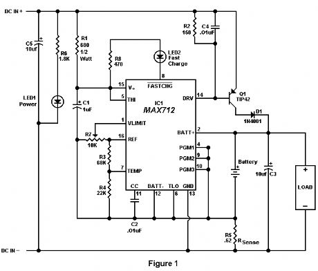
Recently, a fellow amateur was looking for a gel cell charger which would first charge at a fixed rate and then later switch to a trickle charge when the cell was fully charged. After reviewing several catalogs and web sites, the MAX712 IC was discovered. This IC meets all the requirements for almost any type of battery charging system. The circuit in Figure 1 was designed specifically for 12 volt gel cells.
When a discharged gel cell is connected, the charger goes into a fast charge mode at a fixed rate of 400 ma. After the chip detects the voltage leveling off or when 4 1/2 hours has elapsed. (which ever happens first.) the fast charge will stop. After the fast charge has ended, the IC goes into a trickle charge rate of about 50 ma. This trickle charge continues until 13.8 volts is reached which will stop all charging current since the cell is now fully charged. If the cell voltage should drop for any reason, either a fast charge or trickle charge (IC will detect what is needed) will start again.
When constructing this circuit, be sure to attach a small heat sink to Q1. Apply a DC (partially filtered) voltage of at least 15.3 volts. The voltage must never go below this level even under load conditions. Many of the DC wall transformers available will work just fine as long as they meet the minimum voltage requirement. The input voltage can be as high as 24 volts. If the input voltage must be in the 30 volt range, increase R1 to about 820 ohms.
The output voltage must be aligned prior to use. Disconnect the battery from the circuit and apply power. Connect a digital volt meter or other accurate volt meter to pin 2 (positive lead) and to pin 12 (negative lead). Adjust R7 until exactly 13.8 volts is read.
Because this circuit will not overcharge a gel cell, the battery can be connected indefinitely. This circuit is designed primarily as a 12 backup system and can be connected to the load provided the device to be powered only draws current during power line interruptions. Use a diode from the battery to load if needed. This circuit makes an excellent battery backup to an amateur transceiver.
The MAX712 IC and the .62 ohm resistor are available from Digi-Key, 701 Brooks Ave, Thief River Falls, MN 56701 (1-800-344-4539). Order part numbers MAX712CPE-ND and 0.62W-1-ND respectively. All other parts are available at Radio Shack. (View)
View full Circuit Diagram | Comments | Reading(0)
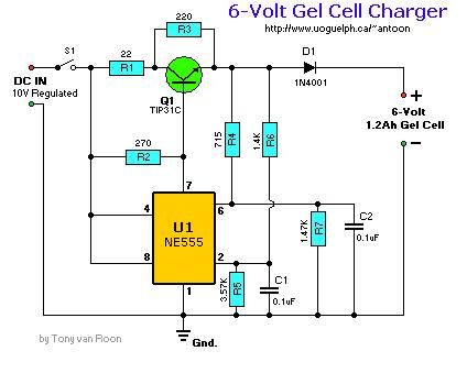
6-V gel cell charger
Published:2012/11/8 1:07:00 Author:muriel | Keyword: 6-V, gel cell charger
View full Circuit Diagram | Comments | Reading(1067)
Cell Phone Helper
Published:2012/11/8 1:05:00 Author:muriel | Keyword: Cell Phone Helper
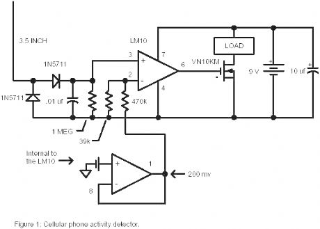
For times when a loud beeping is unacceptable, the load could be a small motor with an offset weight on the shaft so that it vibrates when the phone receives a call. (Add a switch in series with the battery for this application to stop the vibration while you talk.) Or the load could be a lamp or lamp/flasher circuit for a visual indication of an incoming call. The load could be a timer, tape recorder, or even an interrupt line on your laptop to bring up a call logging program. (That one might be rather challenging.) At the other extreme, the detector could be used to generate a louder ringing signal or even honk the horn for when you leave the phone in the car. The circuit will work well from the car’s 12 volt battery and the current consumption is so low that a power switch is not included. The only critical wiring involves the diodes, antenna, and .01uf capacitor. Keep these leads short and the circuit should work fine. If the sensitivity is too high then increase the value of the 39k resistor. Other RF Schottky diodes or fast silicon diodes may be substituted and even 1N914s may work adequately well. Use insulated wire for the antenna and keep it fairly straight although bending the antenna to fit inside a small plastic enclosure won’t hurt the performance much. Substitute a cmos op-amp for the LM10 with different voltage divider values for the trigger reference to reduce the standby current to virtually nothing for applications powered by tiny batteries. (View)
View full Circuit Diagram | Comments | Reading(1301)
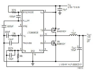
14V to 3.3V Step-Down Converter
Published:2012/10/30 22:22:00 Author:muriel | Keyword: 14V to 3.3V, Step-Down Converter
View full Circuit Diagram | Comments | Reading(1354)
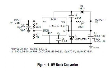
High Efficiency 5V/1A Step-Down Converter circuits
Published:2012/10/30 22:20:00 Author:muriel | Keyword: High Efficiency , 5V, 1A , Step-Down Converter circuits
View full Circuit Diagram | Comments | Reading(2265)
28V to 5V 20A Buck Converter
Published:2012/10/30 22:18:00 Author:muriel | Keyword: 28V to 5V , 20A, Buck Converter
View full Circuit Diagram | Comments | Reading(3026)
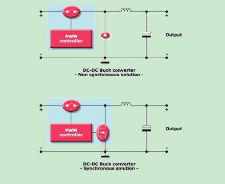
Synchronous Converter with Spread Spectrum Frequency Modulation
Published:2012/10/30 22:15:00 Author:muriel | Keyword: Synchronous Converter, Spread Spectrum, Frequency Modulation
View full Circuit Diagram | Comments | Reading(1458)
LED stepdown power supply - PFM stepdown switcher powers LEDs
Published:2012/10/30 22:12:00 Author:muriel | Keyword: LED , stepdown power supply , PFM, stepdown switcher, powers LEDs

View full Circuit Diagram | Comments | Reading(1026)
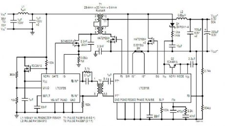
Complete 100W High Efficiency, Low Cost, Minimum Part Count Isolated Telecom Converter
Published:2012/10/30 22:11:00 Author:muriel | Keyword: Complete , 100W , High Efficiency, Low Cost, Minimum Part Count, Isolated Telecom Converter
View full Circuit Diagram | Comments | Reading(1148)
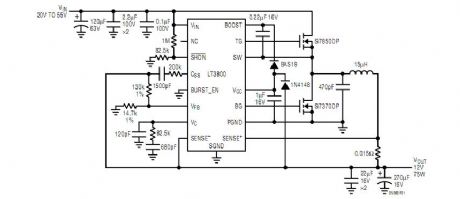
LT3800 12V, 75W Buck DC/DC Converter with High Effi ciency at Light Loads
Published:2012/10/30 22:05:00 Author:muriel | Keyword: LT3800 , 12V, 75W , Buck DC/DC Converter , High Effi ciency , Light Loads
View full Circuit Diagram | Comments | Reading(1920)
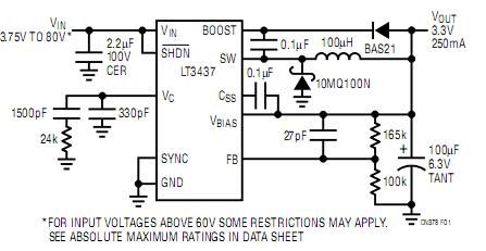
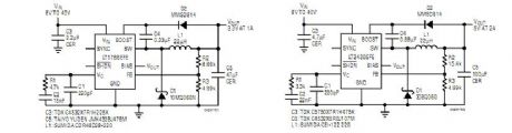
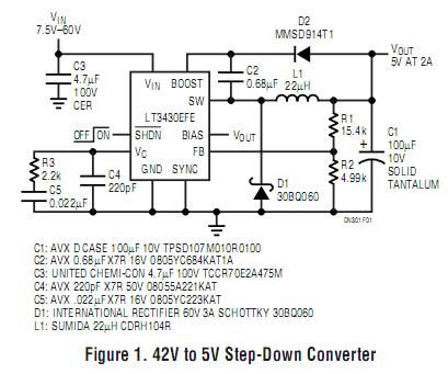
Low Component Count, 8V to 40V IN, 3.3V at 1A OUT DC/DC Converter
Published:2012/10/30 22:02:00 Author:muriel | Keyword: Low Component Count, 8V to 40V, 3.3V, 1A OUT , DC/DC Converter
View full Circuit Diagram | Comments | Reading(1093)
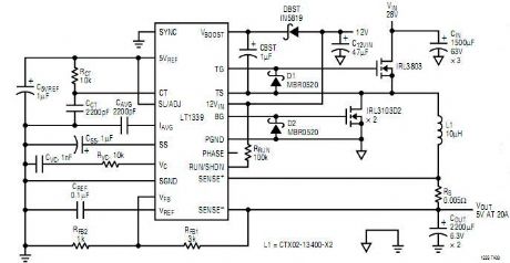
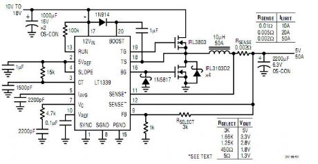
High Power Synchronous Buck Converter Delivers Up to 50A
Published:2012/10/30 21:48:00 Author:muriel | Keyword: High Power , Synchronous Buck Converter, 50A
View full Circuit Diagram | Comments | Reading(5140)
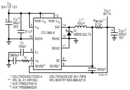
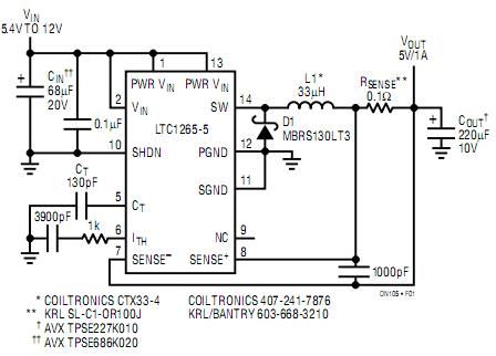
High Efficiency 5V/1A Step-Down Converter
Published:2012/10/30 21:48:00 Author:muriel | Keyword: High Efficiency , 5V, 1A, Step-Down Converter
View full Circuit Diagram | Comments | Reading(1196)
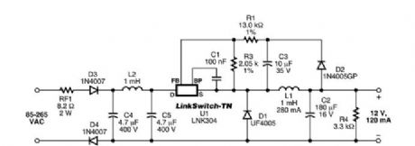
1.4 W Non-Isolated Buck Converter
Published:2012/10/30 21:45:00 Author:muriel | Keyword: 1.4 W , Non-Isolated, Buck Converter
View full Circuit Diagram | Comments | Reading(1951)
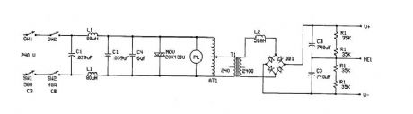
TESLA COIL DRIVER power supply
Published:2012/10/30 21:43:00 Author:muriel | Keyword: TESLA COIL DRIVER , power supply
View full Circuit Diagram | Comments | Reading(1305)
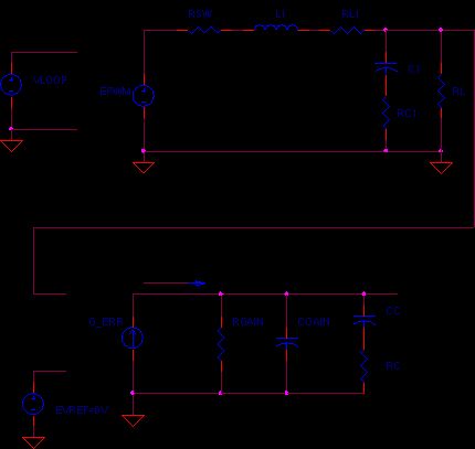
BUCK CONVERTER - AC MODEL
Published:2012/10/30 21:38:00 Author:muriel | Keyword: BUCK CONVERTER, AC MODEL
View full Circuit Diagram | Comments | Reading(992)
Buck Converter
Published:2012/10/30 21:30:00 Author:muriel | Keyword: Buck Converter
View full Circuit Diagram | Comments | Reading(985)
High Efficiency 500kHz, 4.5A Step-Down Converter
Published:2012/10/29 22:07:00 Author:muriel | Keyword: High Efficiency , 500kHz, 4.5A , Step-Down Converter
View full Circuit Diagram | Comments | Reading(876)
60V/3A Step-Down DC/DC Converter
Published:2012/10/29 22:06:00 Author:muriel | Keyword: 60V/3A, Step-Down DC/DC Converter
View full Circuit Diagram | Comments | Reading(4320)
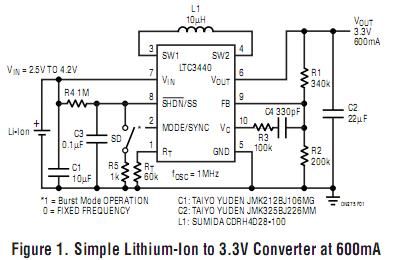
Single Inductor, Tiny Buck-Boost Converter
Published:2012/10/29 22:03:00 Author:muriel | Keyword: Single Inductor, Tiny Buck-Boost Converter
View full Circuit Diagram | Comments | Reading(1654)
| Pages:39/291 At 202122232425262728293031323334353637383940Under 20 |
Circuit Categories
power supply circuit
Amplifier Circuit
Basic Circuit
LED and Light Circuit
Sensor Circuit
Signal Processing
Electrical Equipment Circuit
Control Circuit
Remote Control Circuit
A/D-D/A Converter Circuit
Audio Circuit
Measuring and Test Circuit
Communication Circuit
Computer-Related Circuit
555 Circuit
Automotive Circuit
Repairing Circuit