
power supply circuit
Index 9
6 oxt (1.0) in computer motherboard circuitry _12
Published:2014/1/22 3:41:00 Author: | Keyword: 6 oxt (1.0) in computer motherboard circuitry _12,
As shown in figure 6 oxt (1.0) in computer motherboard circuitry _12 (View)
View full Circuit Diagram | Comments | Reading(843)
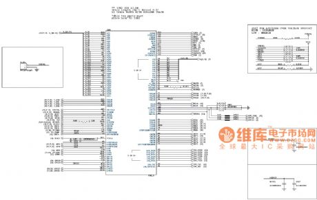
Computer motherboard circuitry _13 6 oxt (1.0)
Published:2014/1/22 3:37:00 Author: | Keyword: Computer motherboard circuitry _13 6 oxt (1.0),

As shown in figure 6 oxt computer motherboard circuitry _13 (1.0) (View)
View full Circuit Diagram | Comments | Reading(851)
Computer motherboard circuitry _15 6 oxt (1.0)
Published:2014/1/22 3:34:00 Author: | Keyword: Computer motherboard circuitry _15 6 oxt (1.0),
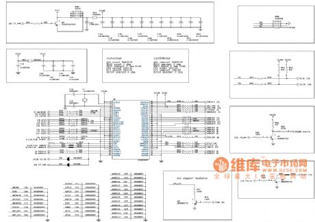
As shown in figure 6 oxt computer motherboard circuitry _15 (1.0) (View)
View full Circuit Diagram | Comments | Reading(805)
Computer motherboard circuitry _16 6 oxt (1.0)
Published:2014/1/21 20:09:00 Author: | Keyword: Computer motherboard circuitry _16 6 oxt (1.0),
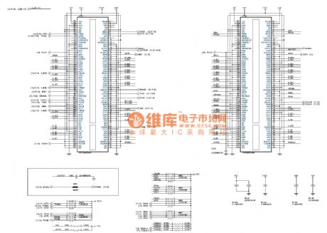
As shown in figure 6 oxt computer motherboard circuitry _16 (1.0) (View)
View full Circuit Diagram | Comments | Reading(752)
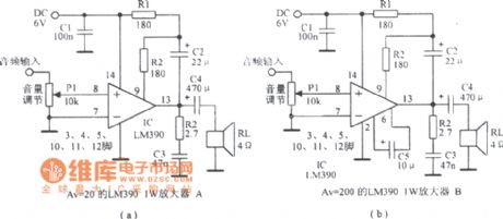
Composed of LM390 practical circuit diagram
Published:2014/1/21 20:05:00 Author: | Keyword: Composed of LM390 practical circuit diagram,
View full Circuit Diagram | Comments | Reading(1162)
Computer motherboard circuitry _17 6 oxt (1.0)
Published:2014/1/21 20:02:00 Author: | Keyword: Computer motherboard circuitry _17 6 oxt (1.0),

As shown in figure 6 oxt computer motherboard circuitry _17 (1.0) (View)
View full Circuit Diagram | Comments | Reading(808)
Overload and three sections of equalization circuit diagram
Published:2014/1/15 18:31:00 Author: | Keyword: Overload and three sections of equalization circuit diagram,
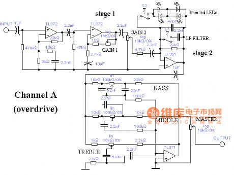
Overload and three sections of equalization circuit diagram as shown (View)
View full Circuit Diagram | Comments | Reading(1090)
Reduce excitation voltage circuit (wideband strain signal conditioner 1B31) circuit diagram
Published:2014/1/14 20:09:00 Author:lynne | Keyword: Reduce excitation voltage circuit (wideband strain signal conditioner 1B31) circuit diagram,
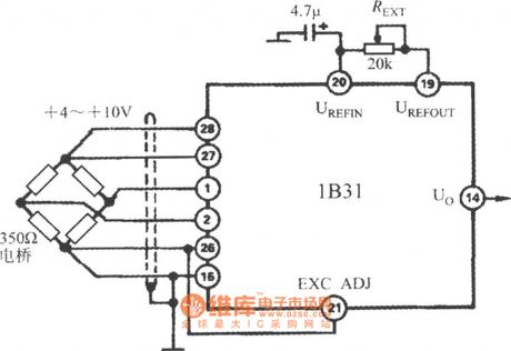
Reduce excitation voltage circuit (wideband strain signal conditioner1B31) circuit diagram shown in Fig.:
(View)
View full Circuit Diagram | Comments | Reading(896)
Noise Gate Noise Gate circuit diagram
Published:2014/1/14 18:31:00 Author: | Keyword: Noise Gate Noise Gate circuit diagram,
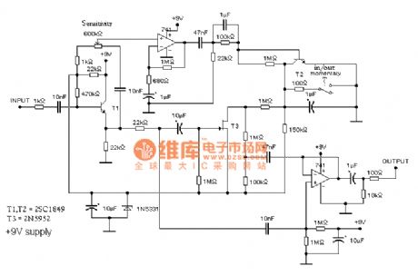
Noise Gate (door) Noise, the Noise of the door design to be in the absence of signal input, can remove Noise, and when a signal is input, covers signal to Noise.
As shown, whose Gate Noise Gate circuit diagram
(View)
View full Circuit Diagram | Comments | Reading(2920)
Equalizer circuit diagram
Published:2014/1/14 18:25:00 Author: | Keyword: Equalizer circuit diagram,
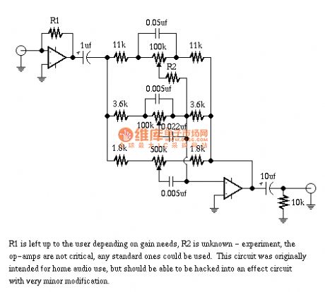
Equalizer circuit diagram as shown (View)
View full Circuit Diagram | Comments | Reading(1253)
Reverberation diagram
Published:2014/1/14 18:24:00 Author: | Keyword: Reverberation diagram,
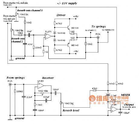
Reverberation diagram as shown (View)
View full Circuit Diagram | Comments | Reading(1056)
A 24 million - bit data circuit diagram
Published:2014/1/9 19:44:00 Author: | Keyword: A 24 million - bit data circuit diagram,
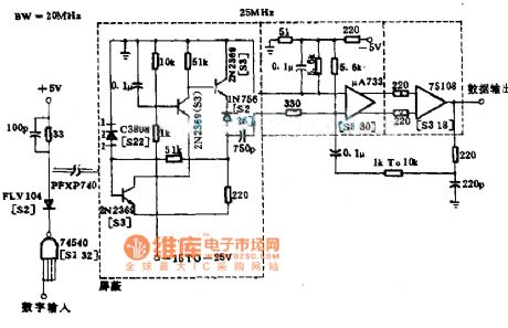
By improving the performance of the receiver, the digital output from the electric typewriter is a message on the far side of feed to the microprocessor, can achieve high data rate for square wave pulse. Pre set designed for use in a limited frequency range to compensate the noise, until about 20 MHZ, has uniform letter/noise ratio. In the demonstration device, the image method in visible light leds and photoelectric detector, at 19.2 cm (40 feet) long cable meet the requirements on its performance.
(View)
View full Circuit Diagram | Comments | Reading(835)
"Welcome, Welcome" sound and light voice / music circuit diagram
Published:2014/1/6 19:43:00 Author: | Keyword: "Welcome, Welcome" sound and light voice / music circuit diagram,
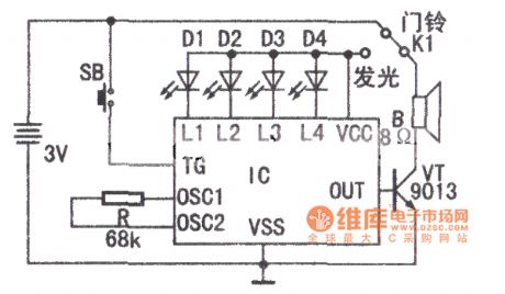
As shown is welcome, welcome to patronize light voice, music integrated circuit principle diagram. IC internal storage is 2 pieces. Welcome, welcome to patronize speech information and seven beautiful melody, high fidelity of the Chinese and foreign famous songs. The voice IC has the following three characteristics: 1. The storage section 2 of speech information can be in accordance with the actual use is divided into: welcome , welcome to patronize , welcome, welcome to patronize single voice or welcome , welcome to patronize 2 audio and welcome , welcome to patronize , welcome, welcome to patronize 3 audio output; 2. A variety of flexible trigger: pulse trigger, trigger level, in order to trigger, random trigger, cycle trigger, etc.; 3. Acousto-optic synchronous/asynchronous flicker, sparkling water, etc. (View)
View full Circuit Diagram | Comments | Reading(1770)
ML - 01 (voice broadcast) are connected to the LM386 g application circuit diagram
Published:2014/1/5 20:37:00 Author: | Keyword: ML - 01 (voice broadcast) are connected to the LM386 g application circuit diagram,
As shown in figure with LM386 power amplifier circuit principle diagram. Figure trimmer potentiometer in VR resistance of 10 k Ω, adjust the output volume. LM386 power output of 500 mw ~ 800 mw. R2, C3, constitute a high-pass filter circuit. Improve the sound quality effect. C4 is 220 mu electrolytic capacitor. Circuit produced, can put the whole circuit board, etc in the speaker speaker internal fixation installation. (View)
View full Circuit Diagram | Comments | Reading(984)
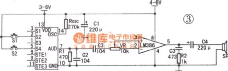
ML - 01 g type automatic play a flag-raising ceremony application-specific integrated circuit diagram
Published:2014/1/5 20:33:00 Author: | Keyword: ML - 01 g type automatic play a flag-raising ceremony application-specific integrated circuit diagram,
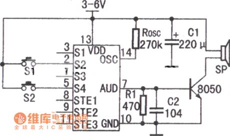
Typical application circuit diagram as shown in figure is ML - 01 g. Figure in the IC is 14 feet dual in integrated circuit, function arrangement and the pin description as shown in table. Use 3 v to 6 v dc power supply. Figure in the resistance ROSC Ω nominal value 270 k. The size of the appropriate change ROSC. Can adjust the rhythm of IC output signal. 470 Ω resistor R1 resistance value, to provide appropriate working point triode. Capacitance C2 104 pf. Improve the sound quality effect; C1 is 220 u F electrolytic capacitor, the filter and the effect of decoupling, NPN transistor T1 for TT - 8050 type low power triode, IC output of audio signal would be enlarged to promote speakers work. S2 is playing music trigger switch, the flag-raising S4 for the flag button switch. The flag-raising, press S2. Start working circuit. The speaker played the national anthem of the People's Republic of China. At the same time IC 9 feet are level of output signals. Driving motor, change gear driving device synchronization flag of raising national flag. The national anthem was over, the national flag just ascended to the flagpole. Flag, start the S4, the circuit no music. IC 8 feet are level of output signals. Descending drive flag electromechanical device, the national flag.
(View)
View full Circuit Diagram | Comments | Reading(931)
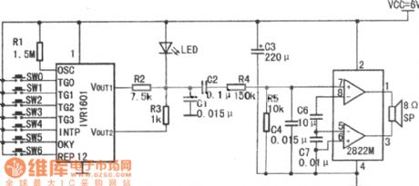
ML - 03 yd type triad voice circuit diagram
Published:2014/1/5 20:32:00 Author: | Keyword: ML - 03 yd type triad voice circuit diagram,
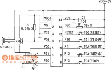
ML - 03 yd type triad voice circuit is a kind of cheap, novel and practical voice IC, has the circuit is simple, less peripheral components, easy to install, do not need to debug, etc. As shown in figure is the circuit principle diagram.
(View)
View full Circuit Diagram | Comments | Reading(1012)
120 seconds countdown music reminders circuit diagram
Published:2014/1/5 20:24:00 Author: | Keyword: 120 seconds countdown music reminders circuit diagram,

The circuit adopts the LM - 4 d200 af must not be embedded microprocessor voice, music memory ROM, dedicated COMS integrated circuit, its working voltage from 5 v to 2.4 v, the static current is less than 5 mu A. LM - type 4 d200 af must not be circuit has 14 feet DIP encapsulation, COB and three DIX chip packaging form for users to choose. (View)
View full Circuit Diagram | Comments | Reading(941)
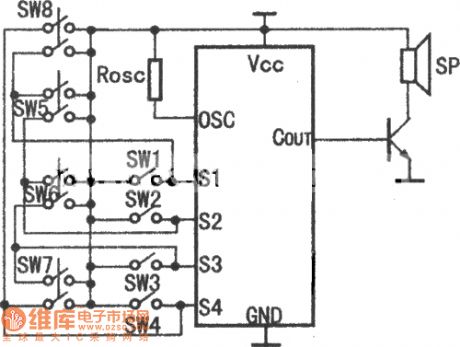
HY8000A eight voice circuit principle diagram
Published:2014/1/2 19:46:00 Author: | Keyword: HY8000A eight voice circuit principle diagram,
View full Circuit Diagram | Comments | Reading(832)
HY8010, HY8020 circuit working principle of the typical circuit diagram
Published:2014/1/2 20:06:00 Author: | Keyword: HY8010, HY8020 circuit working principle of the typical circuit diagram,
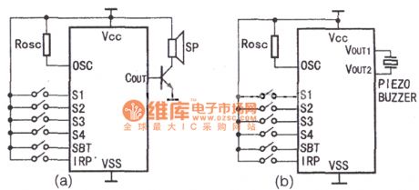
Figure a HY8010, HY8020 circuit principle diagram, typical circuit external triode drive a speaker work, within 50 mw output power. Choose the models such as beta of 150 or 150 small power triode. SP choose 8 Ω impedance, 1/4 w speakers. Figure of Rosc for external vibration resistance, external resistance adjusting the sampling frequency. HY8010 Rosc resistance value between Ω Ω 90 k to 90 k, HY8020 and HY8040 Rosc resistance value between 470 k Ω ~ 2 m Ω selected. Change resistance value can change the playback speed, make its meet the normal requirements. Figure b direct drive piezoelectric buzzer circuit (piezoelectric buzzer resonance frequency of 1 KHZ). Mainly used in electronic mail, voice greeting CARDS and other small products. (View)
View full Circuit Diagram | Comments | Reading(930)
HY8000A external low power audio amplifier circuit principle diagram
Published:2014/1/2 20:05:00 Author: | Keyword: HY8000A external low power audio amplifier circuit principle diagram,
View full Circuit Diagram | Comments | Reading(936)
| Pages:9/291 1234567891011121314151617181920Under 20 |
Circuit Categories
power supply circuit
Amplifier Circuit
Basic Circuit
LED and Light Circuit
Sensor Circuit
Signal Processing
Electrical Equipment Circuit
Control Circuit
Remote Control Circuit
A/D-D/A Converter Circuit
Audio Circuit
Measuring and Test Circuit
Communication Circuit
Computer-Related Circuit
555 Circuit
Automotive Circuit
Repairing Circuit