
Sensor Circuit
Index 23
With Linear Two-Wire RTD Temperature Measuring Circuit (XTR105)
Published:2011/5/12 9:58:00 Author:Robert | Keyword: Linear, Two-Wire RTD, Temperature Measuring
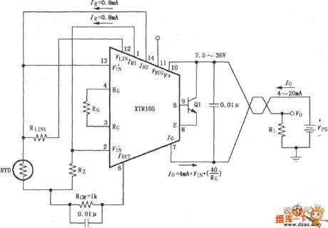
With Linear Two-Wire RTD Temperature Measuring Circuit (XTR105) is show below.
(View)
View full Circuit Diagram | Comments | Reading(1858)
UV sensor schematic circuit
Published:2011/5/5 22:29:00 Author:Sharon | Keyword: UV sensor, schematic
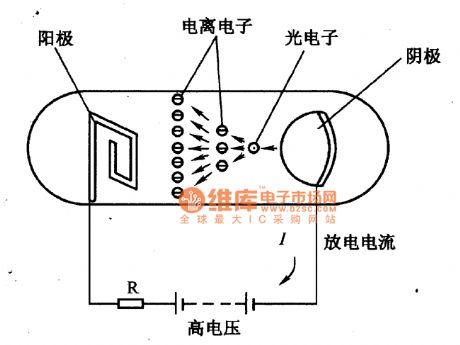
The figure is a schematic circuit of UV sensor. When UV sensor is coupled by voltage between the cathode and anode, and the UV radiation gets through the quartz glass tube on the cathode of the optical surface, because of the cathode material coated with electron emission, cathode will release photoelectrons.Influenced by the strong electric field, photoelectrons will be attracted to the anode, and high-speed movement of optoelectronics will lead to its collision with the gas molecules, which leads to ionization of them. Electron produced by ionization will further collide with gas molecules, and finally the cathode and the anode will be fulfilled by electrons and ions, causing the phenomenon of glow discharge, and the circuit generating a large current.When there is no ultraviolet radiation, there is no electrons and irons flow in the cathode and the anode , showing a very high level of impedance. (View)
View full Circuit Diagram | Comments | Reading(2932)
pressure sensor application circuit
Published:2011/5/5 22:28:00 Author:Sharon | Keyword: pressure sensor, application
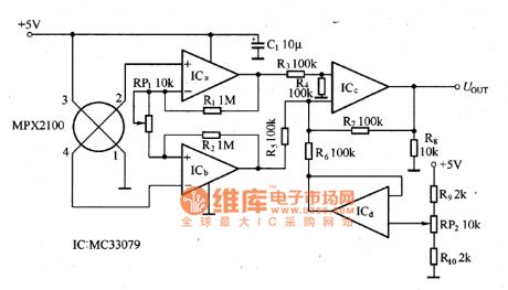
MPX2100 pressure sensor typical application circuit is as shown in the picture. RP1 in thepictureis used for full-scale adjustment, RP2 is used for zero adjustment when the pressure is zero. (View)
View full Circuit Diagram | Comments | Reading(2872)
piezoresistive pressure sensor circuit
Published:2011/5/5 22:28:00 Author:Sharon | Keyword: piezoresistive, pressure sensor,
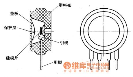
MPX205O and MPX2l00 type pressure sensor is a silicon piezoresistive pressure sensor, with the function of thermistor temperature compensation. The basic elements of its structure is as shown. (View)
View full Circuit Diagram | Comments | Reading(1366)
CL-YB-402 Force Sensor Scheme Circuit
Published:2011/5/6 3:03:00 Author:Sharon | Keyword: Force Sensor, Scheme
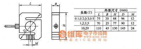
CL-YB-402 force sensor scheme circuithas thecharacteristics of overload and high precision, can be widely used in chemical, mining and other sectors in the truck and railroad track scale.Its dimensions are shown in the figure. (View)
View full Circuit Diagram | Comments | Reading(807)
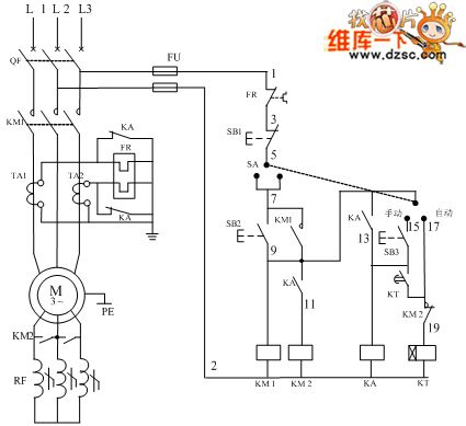
Frequency sensitive rheostat starting principle diagram
Published:2011/5/11 20:49:00 Author:Nicole | Keyword: Frequency sensitive rheostat, starting principle
View full Circuit Diagram | Comments | Reading(1469)
Voltage output integrated temperature sensor LM35 circuit
Published:2011/5/11 1:12:00 Author:Nicole | Keyword: voltage output, integrated temperature, sensor

LM35 output is analog, if you want to obtain digital output, it should use analog/digit converter(ADC). As shown in the figure, it is a ADC08031 type ADC serial output digit temperature transmitter circuit, its full scale is +128℃. In the figure, CLK、ENA are clock terminal and enabling terminal.
(View)
View full Circuit Diagram | Comments | Reading(3305)
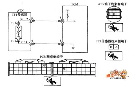
Twist turning position sensor and PCM connection circuit diagram
Published:2011/5/11 2:08:00 Author:Nicole | Keyword: twist turning, position sensor, PCM connection
View full Circuit Diagram | Comments | Reading(775)
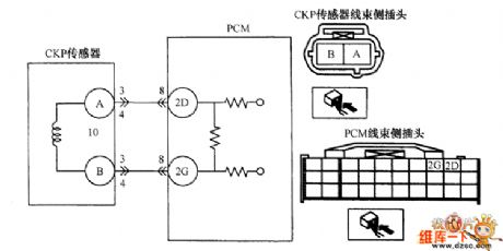
Camshaft position sensor and PCM connection circuit diagram
Published:2011/5/11 2:06:00 Author:Nicole | Keyword: camshaft, position sensor, PCM connection

View full Circuit Diagram | Comments | Reading(1272)
Oxygen sensor and PCM connection circuit diagram
Published:2011/5/11 2:03:00 Author:Nicole | Keyword: oxygen sensor, PCM connection
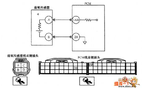
As shown in the figure, it is a oxygen sensor and PCM connection circuit. When the diagnosis instrument displays fault codes: DTCP0031、DTCP0032、DTCP0037、DTCP0038、DTCP0138 and DTCP0140, it shows that the sensor has a hitch, it should be repaired.
(View)
View full Circuit Diagram | Comments | Reading(1427)
Oil temperature sensor and PCM connection circuit diagram
Published:2011/5/11 1:56:00 Author:Nicole | Keyword: oil temperature sensor, PCM connection
View full Circuit Diagram | Comments | Reading(1053)
High Performance Power Amplifier Circuit
Published:2011/5/9 2:03:00 Author:chopper | Keyword: High Performance, Power Amplifier
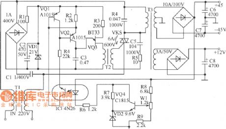
As shown in figure is a high performance power amplifier circuit.It has a feature of small volume,high-power and high-efficiency.Principle of work:AC power is divided into two parts through filtering by T1.One of them is used to reduce voltage of transformer T3.In Primary windings of T3 there is a bidirectional thyristor KS,which is used to change primary AC power of transformer T3.The other one is rectified after voltage reduction by capacitor C1 and provides trigger control circuit with DC working voltage after voltage regulation by VD1.R3、C3、VQ3 and transformer T2 form a oscillating relaxation circuit.R2、R4 and VQ1、VQ2 constitute current supply and offer constant-current charge to capacitor C3.When voltage of C3 reaches the puncture voltage of VQ3,C3 will discharge through the emitter、base of VQ3 and primary coil of transformer T2.And,C3 will get triggering pulse of thyristor KS at the secondary end of transformer T2 and make thyristor conductive, make transformer T3 running.At the secondary end of transformer T3,C3 gains the required positive and negative symmetrical DC voltage of a power amplifier by rectifying and filtering. (View)
View full Circuit Diagram | Comments | Reading(1419)
Light-operated Starter Circuit
Published:2011/5/9 0:37:00 Author:chopper | Keyword: Light-operated, Starter
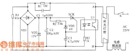
The traditional starter of fluorescent lamp is neon-tube.The start time of neon starter is greatly affected by ambient temperature and voltage,so that its utility is not ideal.As shown in figure is a light-operated starter circuit,it can solve the problems that fluorescent lamps start slowly or cannot start because of temperature reduction and voltage changes.The main component of circuit are thyristor and photo-coupler.When switch K is on,220V commercial power is reduced by fluorescent filament and R1,RC C1 and divided by R4,then,commutated by bridge rectifier VD1,filtered by C2,and through 15V voltage-regulator diode VD2,and,finally,the commercial power offers electricity to unidirectional thyristor and photo-coupler.The control voltage of unidirectional thyristor is offered by voltage-regulator diode VD3 as well as C3 and the thyristor SCR can be connected within 1s.Then,LED of photo-coupler U1 is on power and photistor is connected by light,bringing lots of electric current to fluorescent filament to preheat. Moreover,the conductive photistor makes the control end of electronic starter short and the starter shuts down.Thus,photistor of photo-coupler stops working,which is equal to a filament circuit cut. (View)
View full Circuit Diagram | Comments | Reading(3436)
Phone With Musical Songs(II)Circuit
Published:2011/5/9 0:36:00 Author:chopper | Keyword: Phone, Musical Songs
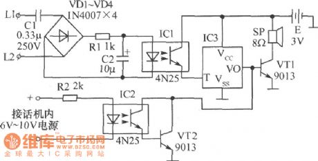
The ring call may make peoplenot able todistinguish which phoneis ringing when one office has many phones.There is a solution that changing the neighboring phone's ringing to different musical sounds.As shown in following figure is a circuit that can do so.IC3 of the figure is a music integration circuit.IC1 and IC2 are photocouplers.When the phone is on-hook,IC1 stops and IC3 outputs nothing,loudspeaker SP does not ring.When there is a call,LED of IC1 will be brilliant because of the AC ringing voltage and the photosensitive tube will be conducted to trigger IC3.The output signal is amplified by VT1 to make SP send out a musical sound.After the phone is off-hook, 6V~10V DC voltage generating within the phone makes IC2 runs, the multiple-unit tube of photosensitive tube and V12 is saturated.Then,output signal of IC3 is short,and SP stops ringing.At this time,the communication is available.The circuit will return to the original state. (View)
View full Circuit Diagram | Comments | Reading(735)
Burglar Alarm Circuit
Published:2011/5/10 0:43:00 Author:chopper | Keyword: Burglar Alarm
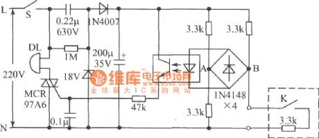
As is shown in figure is a burglar alarm circuit. Detection circuit in the figure adopts resistance bridge and the switch of door adopts magnetic operation switch.The switch will be conducted when door closes while it will be stoped when door opens.The switch and a resistor of electrical bridge form a arm of the electrical bridge,which is set up in the hovel.Thus, if the door is unclenched,the magnetic operation switch will stop;And if exterior line is short or disconnective,in both cases,the bridge circuit will lose balance.The voltage of A、B through rectifier bridge 1N4148 makes optical-coupler run,therefor makes bidirectional thyristor connected and then the bell sends out a alarm.We get supply voltage through the process of voltage reduction by capacitor, half-wave rectification and voltage stabilization by 18V stabilivolt.The switch of door can adopt a magnetic operation switch which is always on as well as microswitch or micro-button.One resistor of the bridge-arms must be set up with the switch.Cut off the power when it needs not to give an alarm,or it will ring even if you yourself opens the door. (View)
View full Circuit Diagram | Comments | Reading(2049)
SL134 integration temperature sensor forming simple thermometer circuit diagram
Published:2011/5/11 1:46:00 Author: | Keyword: integration temperature sensor, simple thermometer
View full Circuit Diagram | Comments | Reading(850)
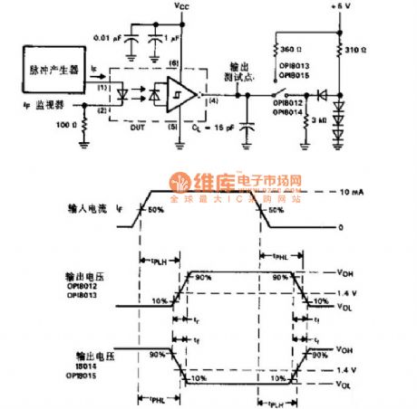
Optical Copuler Switch Sequential Circuit Diagram
Published:2011/5/10 8:08:00 Author: | Keyword: Optical Coupler, Switch, Circuit Diagram
View full Circuit Diagram | Comments | Reading(1043)
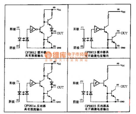
Optical Coupler Series Applied Circuit Diagram
Published:2011/5/10 8:11:00 Author: | Keyword: Optical Coupler Series, Applied Circuit Diagram
View full Circuit Diagram | Comments | Reading(872)
ABS Sensor Circuit
Published:2011/5/10 7:45:00 Author:Robert | Keyword: AB, Sensor
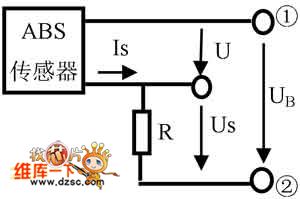
The ABS Sensor Circuit is shown below.
(View)
View full Circuit Diagram | Comments | Reading(857)
Electric automatic check door circuit diagram
Published:2011/5/9 21:26:00 Author:Nicole | Keyword: electric, check door
It is a electric automatic check door circuit diagram, it is fixed a PTC thermal resistor component on the electric check door, this control system is composed of bimetallic strip, electrical heating coil, choke valve relay. When it is lower than the set point of temperature, the choke valve is closed by bimetallic strip, then the starter begins to work, the choke valve relya contact is closed by the voltage of voltage adjuster L terminal, the current flows electrical heating coil, the temperature of bimetallic strip rises, after the temperature rising, the choke valve opens slowly. When the bimetallic strip is heated enough, choke valve opens fully, it uses thermal resistor to control the current of electrical heating coil.
(View)
View full Circuit Diagram | Comments | Reading(1324)
| Pages:23/27 At 2021222324252627 |
Circuit Categories
power supply circuit
Amplifier Circuit
Basic Circuit
LED and Light Circuit
Sensor Circuit
Signal Processing
Electrical Equipment Circuit
Control Circuit
Remote Control Circuit
A/D-D/A Converter Circuit
Audio Circuit
Measuring and Test Circuit
Communication Circuit
Computer-Related Circuit
555 Circuit
Automotive Circuit
Repairing Circuit