
Sensor Circuit
Index 26
Grain and cotton warehouse exaggerated humidity automatic ventilating and language admonishment circuit
Published:2011/4/27 9:16:00 Author:Nicole | Keyword: grain warehouse, cotton warehouse, automatic ventilating, language admonishment
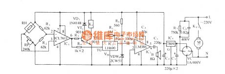
The circuit is as shown, it is composed of humidity sensitivity electric bridge network, comparison circuit, relay control ventilating circuit, language phonation circuit and AC depressurization rectifier circuit . When the warehouse hunidity is exaggerated, the circuit will automatically connect to ventilating fan, and send out admonishment language, to remind the personnel on duty of taking a note. RH is humidity sensor,a bridge testing humidity network is composed of RH, RP1, R1, R2. When the environmental humidity is within the normal range, sensor RH has a large resistance. (View)
View full Circuit Diagram | Comments | Reading(1071)
ZD—30C and ZD-30D automatic gravimetric filling instrument photo-sensitive circuit
Published:2011/5/2 7:17:00 Author:Nicole | Keyword: automatic gravimetric filling instrument, photo-sensitive
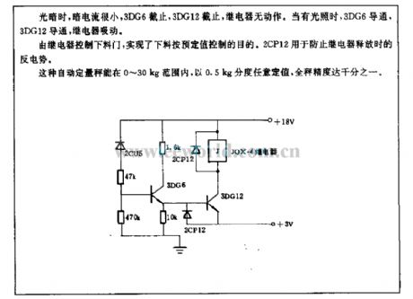
When it is low brightness, the current is small, 3DG6 turns off, 3DG12 turns off, relay has no action. When it has light, 3DG6 turns on, 3DG12 turns on, relay pulls up.
The baiting gate is controlled by relay, it can accomplish the aim of baiting as the desired value. 2CP12 is used to prevent the Back EMF released by relay.
This automatic gravimetric filling instrument can set value with 0.5kg graduation discretionarily in the range of 0~30kg, the precision can reach millesimal. (View)
View full Circuit Diagram | Comments | Reading(1344)
Simple pressure sensor amplification circuit diagram
Published:2011/5/2 7:06:00 Author:Nicole | Keyword: pressure sensor, amplifition
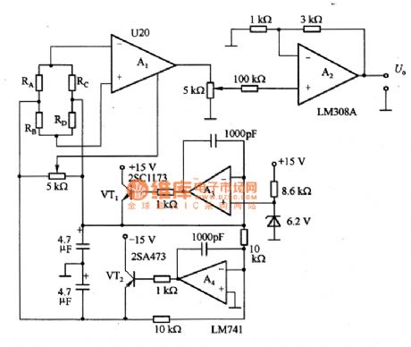
The figure 1 is a simple pressure sensor amplification circuit. Preamplifier A1 adopts 200 times fixed gain pressure sensor special preamplifier U2O. When it is standard load, you can use four and a half digital voltmeter to ontain data, the sensitivity is 2mV/V.
(View)
View full Circuit Diagram | Comments | Reading(3522)
Temperature Sensor of Current Transmission Circuit
Published:2011/5/1 22:30:00 Author:Felicity | Keyword: Temperature Sensor of Current Transmission Circuit,
The resistance in the cirtuit is metal film one. Itsaccuracy is better than 1% and temperature coefficient TCis less than ±50X10-6/K.The measuring range is from0℃ to 100℃. Current I= 4+T/6.25. The temperate unit is ℃ and the current unit is mA. The current shows KTY87two-wire current transmitter consisting of Wheatstone bridge with pre-amplifier , current transmitter stage and voltage regulator. (View)
View full Circuit Diagram | Comments | Reading(1019)
Infrared Detection Electric Shock Protection And Warning Circuit
Published:2011/5/2 4:11:00 Author:Robert | Keyword: Infrared Detection, Electric Shock Protection And Warning
Infrared Detection Electric Shock Protection And Warning Circuit is shown below:
(View)
View full Circuit Diagram | Comments | Reading(1135)
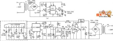
Centigrade thermometre circuit
Published:2011/4/28 21:59:00 Author:Nicole | Keyword: centigrade thermometre
SL134 is three terminal type IC, it is used as temperature sensor. The measuring range is -55~+125℃, its exterior has two kinds: metal package and plastic package. The work voltage range of V+~V- is V±=0.9~30.0V, the current I+=Is+I-, Is=0.01~5.00mA, I+/I-=14~26, the maximum allowable value between R-V is 5V, the maximum allowable power consumption PD=200mW. Under the normal situation, the R-V voltage value temperature factor is about +227μV/K.
In this circuit, Ci is used to prevent SL134 self-excited, C2 and C3 are used to 5GOP-07 power supply decoupling, 5G1403 is as the core to form 5GM14433 three and a half digital display voltmeter. To change R3 or R6 then Vx will change in relation to the temperature with the proportion of 10mV/℃, to change Q1 can make Vx=0V when T=0℃. (View)
View full Circuit Diagram | Comments | Reading(734)
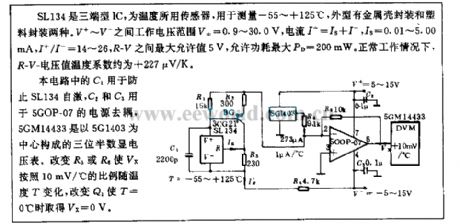
XTR101 Thermocouple Input Circuit
Published:2011/4/26 8:05:00 Author:Robert | Keyword: Thermocouple
The circuit shows the thermocouple input circuit withtwo temperature zones and diode cold junction compensation. This circuit uses J-type thermocouple as temperature sensor, semiconductor diode Das cold junction temperature compensation to form the relative 0oC of the measurement, to measure the temperature, T1 temperature range is from 0 to 1000oC. The temperature of T2 is equal to the temperature TD of semiconductor diode D. When the measured temperature changes in the range of 0to 1000oC, J-type thermocouple will have a 58mV change. When the ambient temperature is +25oC, the typical value would be 1.28mV. Corresponding 0oC transmission current is 4mA, corresponding 1000oC transmission current is 20mA.
(View)
View full Circuit Diagram | Comments | Reading(1550)
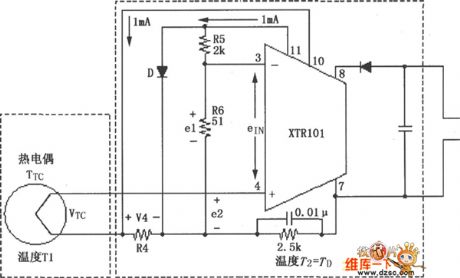
Pressure sensor excitation circuitry diagram
Published:2011/4/26 2:50:00 Author:Nicole | Keyword: pressure sensor
The figure 1 is a pressure sensor excitation circuit. Figure1(a) is generic constant voltage excitation circuit, it is composed of Zener diode VD1, operational amplifier and LM741; Figure1(b) is constant current excitation circuit, its stability is decided by Rl一R4, so it should choose the resistance with low temperature coefficient. The temperature stability of this excitation circuit should be designed to 1/100 of sensor. Such as the temperature stability of sensor is 0.1%, then the excitation circuit is 0.001%.
(View)
View full Circuit Diagram | Comments | Reading(1950)
Three phase SCR trigger
Published:2011/4/25 3:05:00 Author:Nicole | Keyword: three phase SCR, trigger

XMA5000 series regulator sends out three phase SCR trigger pulse instruction, and it emits six SCR phase shift trigger or zero-crossing trigger control singal, it is used to control the main loop SCR trigger conduction. It adopts unique trigger control circuit, it can trigger 3A~1000A unidirectional or bidirectional SCR.
(View)
View full Circuit Diagram | Comments | Reading(1898)
Multi-Channel Pressure Detection Apparatus Circuit Schematic Diagram
Published:2011/4/23 3:16:00 Author:Robert | Keyword: Multi-Channel, Pressure, Detection Apparatus
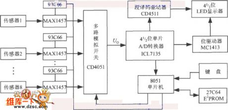
View full Circuit Diagram | Comments | Reading(786)
Blind Pathfinder Circuit
Published:2011/4/23 8:53:00 Author:Robert | Keyword: Blind Pathfinder
Blind Pathfinder Circuit is shown below:
(View)
View full Circuit Diagram | Comments | Reading(1462)
Storehouse humidity detection and automatic ventilating air exhausting device circuit(MS01-A)
Published:2011/4/20 20:54:00 Author:Nicole | Keyword: storehouse, humidity detection, automatic ventilating, air exhausting device

The circuit is as shown, it is composed of precise time base oscillator, D trigger, temperature detection circuit, comparison circuit, relay control ventilating circuit, language admonishment circuit and AC depressurization rectifier circuit. BC adopts the crystal in silica watch, its natural frequency is 32768Hz; K1 adopts JZC-22F; C6, C7 adopt CD11-16V electrolytic capacitor; R10 adopts RJ-2W-820kΩ, RP1 adopts WH5 synthetic film potentiometer, the other resistances all adopt RT-1/8W carbon-film potentiometer; C8 uses CBB-400V-0.75μF; VC uses 1A/400V full bridge rectifier module or four 1N4004 to build a bridge rectifier; B uses 0.25W(8Ω) electricity-powered loudspeaker. (View)
View full Circuit Diagram | Comments | Reading(935)
valuables pilfering tracker circuit diagram 2
Published:2011/4/15 2:28:00 Author:Rebekka | Keyword: valuables pilfering tracker
View full Circuit Diagram | Comments | Reading(1069)
Limiting voltage trigger circuit diagram
Published:2011/4/15 2:30:00 Author:Nicole | Keyword: Limiting voltage, trigger
View full Circuit Diagram | Comments | Reading(1120)
The photosensitive control circuit applied in weaving machine triple run digital controller
Published:2011/4/8 2:47:00 Author:Nicole | Keyword: weaving machine, digital controller
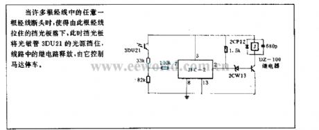
When one of warps is broken, the baffle which is hold on to the warp will fall, and the light source of photosensitive tube 3DU21 is blockaded by the baffle. The relay releases, and to control the motor stopped. (View)
View full Circuit Diagram | Comments | Reading(919)
Orthogonal moving-magnet simulated watch movements drive circuit diagram
Published:2011/4/1 3:33:00 Author:Nicole | Keyword: simulated watch movements drive
View full Circuit Diagram | Comments | Reading(892)
10-bit low-power digital temperature sensor application circuit
Published:2011/3/23 3:04:00 Author:Joan | Keyword: low-power , digital temperature sensor , application circuit
Below is 10-bit low-power digital temperature sensor application circuit.
(View)
View full Circuit Diagram | Comments | Reading(793)
Infrared wireless alarm sensor circuit
Published:2011/3/21 1:28:00 Author:Joan | Keyword: Infrared sensor, wireless sensor, alarm sensor
Infrared wireless alarm sensor circuit. (View)
View full Circuit Diagram | Comments | Reading(1011)
Infrared automatic faucet schematic
Published:2011/3/21 1:27:00 Author:Joan | Keyword: Infrared faucet, automatic faucet, automatic faucet
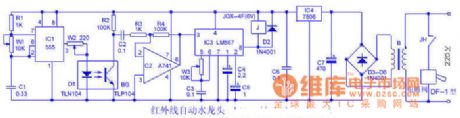
How it works:The circuit is shownas the figure. IC1 and W1, C1 and other components compose a 30 ~ 50KHz frequency pulse oscillator. It drives the infrared light-emitting diode D1 to send modulated infrared light. When someone close to the faucet for washing hands or hold water, a part of the the infrared ray emitted by the D1 which reflected back by the human body part is received by BG and then is amplified by op amp IC2 and then input to pin 3 of the audio decoder LM567. After decoding and dentifying it, the IC3 makes pin 8 output low. Relay J pulls in, normally open contact point JH connects to the solenoid valve power. Electromagnetic valve is opened, the faucet water automatically. When the human body leaves the faucet, BG lost infrared signal, then the circuit returns to the general state of waiting for work.
Debug: Cover up D1 and BG by iron sheet. Tunning W1, W3 can make the infrared transmitter and receiver of the same frequency. When the human body is close to the faucet, the solenoid valve can reliably act. Regulating W2 resistance can change the D1 emission current, then the circuit can control the effective action distance when the human body close to the faucet(ie, sensitivity). (View)
View full Circuit Diagram | Comments | Reading(3647)
Differential temperature measurement Circuit Diagram
Published:2011/3/21 0:52:00 Author:Joan | Keyword: temperature measurement, Differential temperature
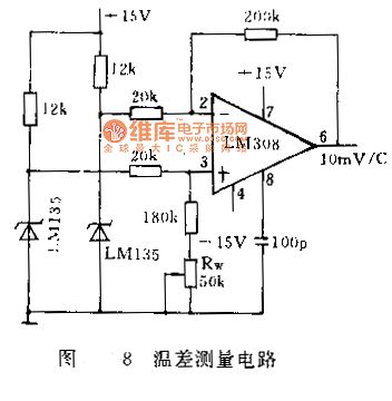
The temperature difference between two points is often measured in many situations. For example, in water pump fan design and other designs, the impeller shape is always detemined by the temperature difference between the entrance and exit. if the difference is small, it requires high precision phase resolution. Figure 8 shows a high sensitivity temperature measurement circuit with 100mV / ℃ sensitivity. The precision op amp LM308 ouput 10 times of the differential temperature voltage the two temperature sensors measured. The Op amp output will be 0 by adjust the Rw when the two sensors are in the same temperature.
(View)
View full Circuit Diagram | Comments | Reading(2842)
| Pages:26/27 At 2021222324252627 |
Circuit Categories
power supply circuit
Amplifier Circuit
Basic Circuit
LED and Light Circuit
Sensor Circuit
Signal Processing
Electrical Equipment Circuit
Control Circuit
Remote Control Circuit
A/D-D/A Converter Circuit
Audio Circuit
Measuring and Test Circuit
Communication Circuit
Computer-Related Circuit
555 Circuit
Automotive Circuit
Repairing Circuit