
Sensor Circuit
Index 27
-55-+150℃ Digital thermometer circuit diagram
Published:2011/3/30 20:52:00 Author:Ecco | Keyword: -55-+150℃ Digital thermometer
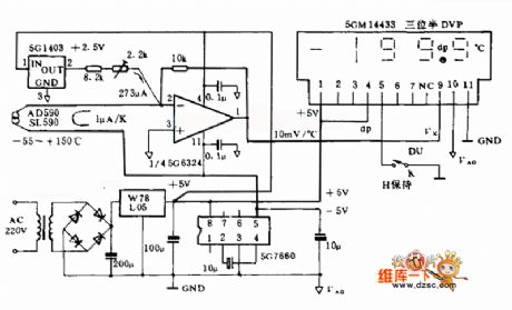
This digital thermometer electrocircuit is composed of SL590, a new semiconductor IC temperature-sensitive sensor and three half digital voltage panel 5GM14433, and it can measure the temperature in the range of -55~15o ℃. The SL590 make the temperature be a type of current semaphore, which become ratio's voltage semaphore at Celsius temperature after making the null point displacement by operational amplifier, and sent to the UX input terminal of 5GM14433, then be digital quantity displayed by LED. The supply is d.c two types, and alternating current supplyed by 220V, also could be supplyed by 4 pieces of 1.5V batteries.
(View)
View full Circuit Diagram | Comments | Reading(3201)
-40-+125℃ digital thermometer circuit diagram
Published:2011/3/30 20:42:00 Author:Ecco | Keyword: digital thermometer
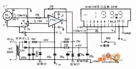
This digital thermometer electrocircuit is composed of SL616, a newsemiconductor IC temperature-sensitive sensor and three half digital voltage panel(DVP)s, and it uses the SL616 A to measure the temperature in the ranges of -40~125 ℃. And it uses the SL161 C to measure the temperature in the ranges of -25~85 ℃, measurement accuracy after correcting is ±0.5 ℃. Its power supply use 3 sets of +6 V, ±the 10, and only +6 V power supply consume higher current(about the 65 mas), each ±10 V power supply the only consume about 3 mA current.
The digital thermometer creates corresponds thermal voltage semaphore(-10 mVs/K), then the semaphor is become ratio's voltage semaphore(+10 mVs/℃) at Celsius temperature after making the null point displacement by operational amplifier, and sent to DVP to carry on digitize display as thermal amount of indication.
(View)
View full Circuit Diagram | Comments | Reading(2396)
Intelligent pressure measurement and control circuit diagram
Published:2011/3/20 22:56:00 Author:Ecco | Keyword: Intelligent pressure measurement and control
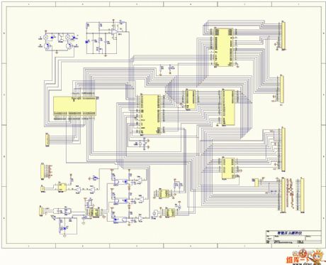
Intelligent pressure measurement and control circuit diagram is as below:
(View)
View full Circuit Diagram | Comments | Reading(1389)
Fahrenheit scale circuit diagram
Published:2011/3/20 22:56:00 Author:Ecco | Keyword: Fahrenheit scale
Fahrenheit scale circuit diagram is as below:
(View)
View full Circuit Diagram | Comments | Reading(950)
Light sensing circuit diagram
Published:2011/3/27 22:25:00 Author:Ecco | Keyword: Light sensing
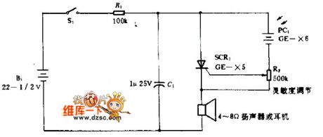
In the silicon-controlled trigger circuit, cadmium sulfide cell connects the relaxation oscillator before having a sensor to blink in darkroom. That make the speaker emit the warning sound of Ka, Li . The rate of the sound will increase with the quantity of light. When there is no blink, to modulate R2 until it's lower than the limiting value of sound. The circuitry is applied in fire warning system, and it uses the cadmium selenylation cell to replace PC1, as cadmium sulfide cell is more sensitive to infrared rays; when it's applied in temperature warning system, the optical spectrum expands to far infrared region, plumbum sulfide cell is applied in the circuitry as it is more sensitive to infrared rays.
(View)
View full Circuit Diagram | Comments | Reading(1910)
TSV temperature sensor temperature-measuring circuit with constant current source
Published:2011/3/21 1:30:00 Author:Allen | Keyword: TSV, temperature sensor, constant current source

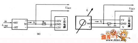
In the figure, when using a constant current source as the load, the load current will remain stable, the voltage drop of lead resistance is a constant value, so the output voltage changes at 10mV / ℃ rule. Generally, the control distance is up to kilometer. (View)
View full Circuit Diagram | Comments | Reading(711)
TSV temperature sensor typical application circuit
Published:2011/3/21 1:29:00 Author:Allen | Keyword: TSV, temperature sensor

In the circuit, the temperature sensitivity of output voltage, Vo is 10mV/℃; R is a current limiting resistor; careerist C is used to improve the circuit stability. The voltage drop on lead resistance will introduce some measurement error, when the test location is far away the reading location. (View)
View full Circuit Diagram | Comments | Reading(667)
LT series current sensor connection chart
Published:2011/3/20 22:50:00 Author:Ecco | Keyword: LT series, current sensor connection chart
LT series current sensor connection chart
(View)
View full Circuit Diagram | Comments | Reading(927)
Power converter circuit diagram for switching reluctance motor
Published:2011/3/22 3:16:00 Author:Nicole | Keyword: power converter, switching reluctance motor
View full Circuit Diagram | Comments | Reading(901)
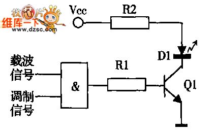
modulation and infrared emission drive circuit diagram
Published:2011/3/22 19:58:00 Author:Nicole | Keyword: modulation, infrared emission drive
View full Circuit Diagram | Comments | Reading(817)
Heater and Pump Drive Circuit Diagram
Published:2011/3/22 2:36:00 Author:Nicole | Keyword: Heater, Pump Drive
View full Circuit Diagram | Comments | Reading(807)
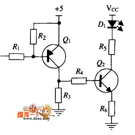
Infrared sensing drive circuit diagram
Published:2011/3/20 22:56:00 Author:Nicole | Keyword: Infrared sensing
View full Circuit Diagram | Comments | Reading(868)
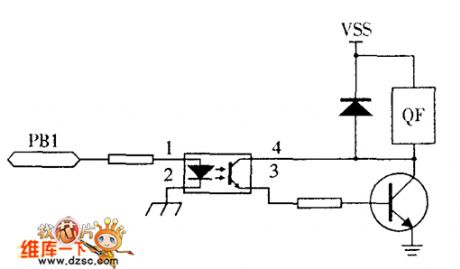
electromagnetic gas valve drive circuit diagram
Published:2011/3/20 22:52:00 Author:Nicole | Keyword: electromagnetic gas valve drive
View full Circuit Diagram | Comments | Reading(779)
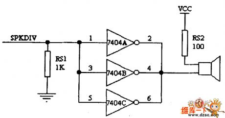
Buzzer and its Drive Circuit Diagram
Published:2011/3/21 4:26:00 Author:Nicole | Keyword: Buzzer
View full Circuit Diagram | Comments | Reading(968)
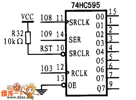
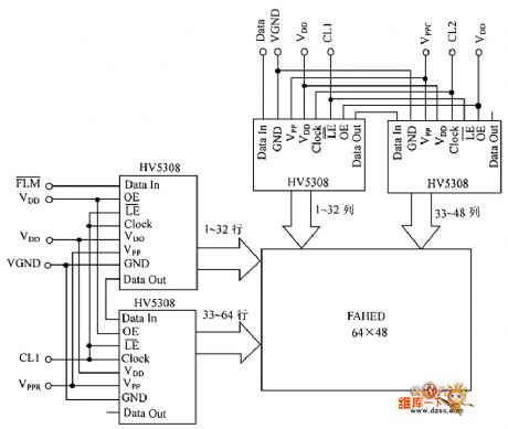
HV5308 SerDes chip on the new pattern flat display drive circuit diagram
Published:2011/3/20 22:44:00 Author:Nicole | Keyword: SerDes chip
View full Circuit Diagram | Comments | Reading(942)
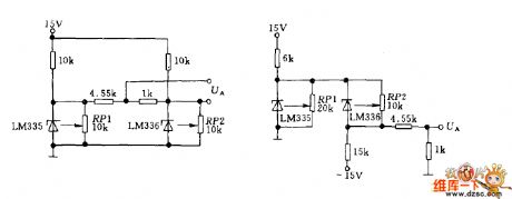
LM135 temperature telemetry circuit
Published:2011/3/21 1:46:00 Author:Joan | Keyword: LM135 , temperature telemetry
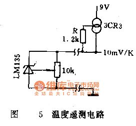
When the measurement point is far away from the display meter, the voltage drop caused by the sensor's operating current in the connection conductor, superimposed on the output voltage on the sensor, will produce some measurement error. To eliminate the effect of the resistance of connecting wires, the circuit can be used as shown in Figure 5. By the use of constant current source driver LMl35, the sensor operating current is constant, and the connection lead resistance is fixed, then the voltage drop across the wire is a certain value, which can be corrected by calibration terminal to ensure the accuracy of measurements.
(View)
View full Circuit Diagram | Comments | Reading(1417)
LM135 package and pin function circuit
Published:2011/3/18 1:53:00 Author:Joan | Keyword: package, pin function
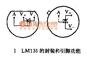
LM135 Series Temperature Sensor is a voltage output type precision integrated temperature sensor. It works similar to the Zener diode, the reverse breakdown voltage changes with the absolute temperature in +10 mV/K ratio. The working current is 0.4 - 5mA, and the dynamic impedance is 1Ω, which facilitate matching to instruments. The temperature sensor features high accuracy and simple application. LMl35 series temperature sensor has wide temperature measurement range of -55 to +150 ℃. LM235 and LM335 temperature measurement ranges of -40 - +125 ℃ and -40 - +100 ℃. The short-term use temperature measurement limit can be widened, respectively, to 200 ℃, 150 ℃ and 125 ℃.
(View)
View full Circuit Diagram | Comments | Reading(1185)
LM135 Series Internal schematic diagram
Published:2011/3/18 1:28:00 Author:Joan | Keyword: Internal schematic diagram
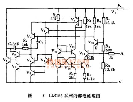
LM135 Series Internal schematic diagram
(View)
View full Circuit Diagram | Comments | Reading(1209)
LM135 thermocouple cold junction compensation temperature measurement circuit
Published:2011/3/17 1:55:00 Author:Joan | Keyword: thermocouple, cold junction compensation, temperature measurement
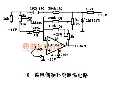
The figure is a practical circuit with a wide temperature measurement range using thermocouple. It uses indexing number for K thermocouple, measuring maximum temperature up to 1000 ℃. In order to eliminate the environmental impact of the Thermocouple cold junction, LM335 is used to measure the cold junction temperature, and then the operational amplifier LM308 amplifies output voltage after superposition of the temperature voltage signal and thermoelectric power generated by the thermocouple, so that the output voltage signal reflects the true temperature of the thermocouple working end. As the LM335 output voltage is proportional to absolute temperature, LM329 and resistor distributed voltage generate voltage signal to offset the output voltage at 0 ℃. The corresponding relationship between the circuit output voltage and the measured temperature is adjusted 10mV / ℃ by the amplifier.
(View)
View full Circuit Diagram | Comments | Reading(3470)
| Pages:27/27 At 2021222324252627 |
Circuit Categories
power supply circuit
Amplifier Circuit
Basic Circuit
LED and Light Circuit
Sensor Circuit
Signal Processing
Electrical Equipment Circuit
Control Circuit
Remote Control Circuit
A/D-D/A Converter Circuit
Audio Circuit
Measuring and Test Circuit
Communication Circuit
Computer-Related Circuit
555 Circuit
Automotive Circuit
Repairing Circuit