
Sensor Circuit
Index 20
Resistor and capacitor (LC) circuit
Published:2011/6/19 3:44:00 Author:John | Keyword: Resistor, capacitor
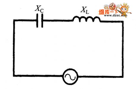
If a circuit uses both inductors and capacitors at the same time, they combine to form the inductor - capacitor (LC) resonant circuit, also known as energy storage circuit or the oscillator circuit. This circuit can be used in the radio receiver’s tuned circuits and other applications.
(View)
View full Circuit Diagram | Comments | Reading(1895)
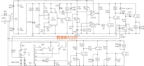
Micro vibration sensor alarming circuit diagram
Published:2011/6/23 21:51:00 Author:Nicole | Keyword: Micro vibration, sensor alarming
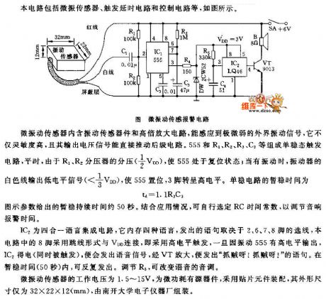
This circuit includes micro vibration sensor, trigger delay circuit and control circuit, the figure is as shown.
The micro vibration sensor contains vibration sensor device and high power amplifier circuit, it can induce very weak external vibration signal, it has high sensitivity, and its output voltage signal can push the backward stage circuit directly. The monostable trigger cirucit consists of 555 and R1, R2, R3, C3, ordinarily, due to the partial pressure(1/2VDD)of R1, R2 voltage dividers, 555 is in reset state; when it is vibration, the vibrator's white line outputs low level signal(<1/3VDD), 555 is set, 3 foot turns to high level. The short steady time of the monostable circuit is td=1.1R3C3. The short steady duration time of graphic parameter is about 50s.
(View)
View full Circuit Diagram | Comments | Reading(2615)
Infrared sensor high voltage dangerous voice warning circuit diagram
Published:2011/6/23 20:40:00 Author:Nicole | Keyword: infrared sensor, dangerous voice warning
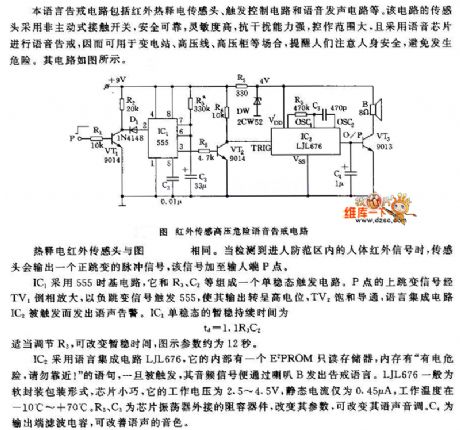
Pyroelectric infrared sensor head is same with the figure. When it detects the human body infrared signal in guarding zone, the sensor head will output a positive jump pulse signal, this signal is added to input terminal P point.
IC1 adopts 555 time base circuit, the monostable trigger circuit is composed of 555 and R3, C2. P's jump signal is phased and amplified by TV1, 555 is triggered by negative jump signal, its output turns to high level, TV2 is saturation conduction, language integrated circuit IC2 is triggered, and it sends out voice warning. The short steady duration time of IC1 monostable is td=1.1R3C2. Adjusting R3 properly, the time can be changed, the graphic parameter is about 12s.
(View)
View full Circuit Diagram | Comments | Reading(2126)
The plate shape chloride steel humidity sensitive resistor circuit
Published:2011/6/22 9:28:00 Author:Christina | Keyword: plate shape, chloride steel, humidity sensitive, resistor
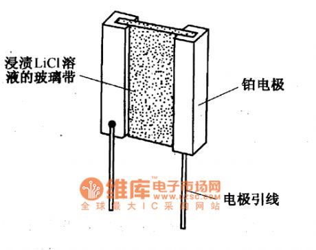
The plate shape chloride steel humidity sensitive resistor circuit is as shown in the figure. You can dip the Lithium chloride solution on the non-alkali glass ribbon to form the humidity sensitive component. The platinum electrode is inosculated with the glass ribbon by the pressure production method, and it is led out by the welding wire.
(View)
View full Circuit Diagram | Comments | Reading(1059)
Digital tachometer circuit based on the magnetic sensor
Published:2011/6/22 21:30:00 Author:TaoXi | Keyword: Digital tachometer, magnetic sensor
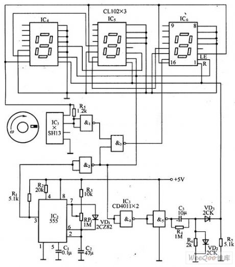
The digital tachometer circuit is as shown in the figure. It is composed of the disk with the permanent magnet, the Hall integrated sensor, the selective passing gate circuit, the time base signal circuit, the power count circuit and the digital display circuit. The count circuit and the digital display circuits use the CMOS-LED digital display component CLlO2, it can count and display the numerical code.
The input shaft of the turntable is connected with the measured rotating shaft, when the measured rotating shaft is rotating, it will drive the turntable to turn with it. When the small permanent magnet of the turntable is getting through the Hall integrated sensor IC1, IC1 will change the magnetic signal into the speed electric signal. This signal reverse-phase inputs to the input port of the NAND gate 3 through the NOT gate l. (View)
View full Circuit Diagram | Comments | Reading(5728)
Blood Pressure Sensor Circuit
Published:2011/6/12 10:35:00 Author:Robert | Keyword: Blood Pressure, Sensor
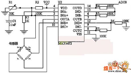
As shown in the picture, this circuit uses BP01 type pressure sensor and operational amplifier MAX4472. The BP01 type pressure sensor is specially designed for blood pressure which is mainly used in portable electronic blood pressure meter. It uses the precise thick-film ceramic chip and nylon plastic package and it features high linearity, low noise and small external stress. Also it uses internal standard and temperature compensation method to improve the measuring accuracy, stability and repeatability. In its full measuring range the accuracy is ±1%, the zero point distortion would not be more than ±300μV. The MAX4472 is a MAXIM company's low-power amplifier chip with four integrated operational amplifiers.
(View)
View full Circuit Diagram | Comments | Reading(4713)
The TV auto brightness adjusting circuit composed of LDR
Published:2011/6/15 20:31:00 Author:Borg | Keyword: brightness adjusting circuit
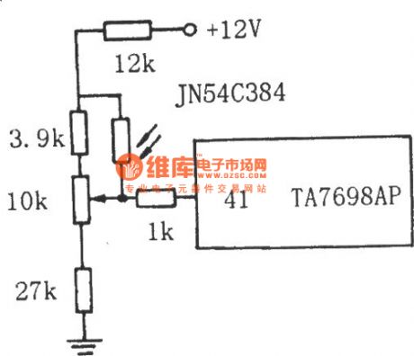
The TV auto brightness adjusting circuit composed of LDR See as the figure, the LDR is connected with the middle head of the contrast potentiometer. By the LDR feature that its resistance changes with the brightness of the rays, the LEV on the middle head of the potentiometer changes with the brightness of the rays, then by the control of decoding circuit TA7698AP, the brightness, contrast ratio and saturation of the TV change accordingly. When the rays are bright, the resistance of GR is low, and the LEV on the middle head of the potentiometer is rising. (View)
View full Circuit Diagram | Comments | Reading(1378)
The new bicycle charger
Published:2011/6/15 20:51:00 Author:Borg | Keyword: bicycle charger
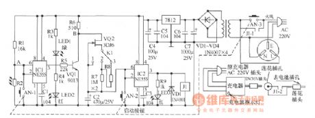
(1)working principle: insert the three-prong plug of charger AC220V into the AC power supply outlet of the device, insert the 36v plug into the lotus hole of the device and connect the AC220V three-prong to the mains(after the above are done, no more actions are needed). When charging, just insert the charging battery hole lotus plug into the hole of the electric bicycle. Press the starting key AN, then AN-1, AN-2 and AN-3 are connected, the charger and AC220V power supply are also on; as AN-2 is on, the 2-pin and 6-pin of IC2 are connected with the earth. (View)
View full Circuit Diagram | Comments | Reading(1359)
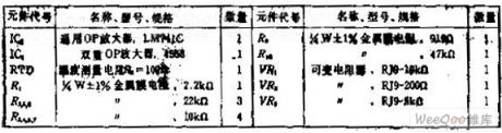
The half-wave rectifier circuit-single phase half-wave rectifier circuit
Published:2011/6/16 6:01:00 Author:Seven | Keyword: half-wave rectifier
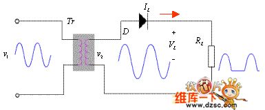
The half-wave rectifier is a motor that uses the single conducting way feature of the diode, and makes half of the voltage V0 from the transformer reach the load, finally makes the loading voltage VL be a single way pulse DC voltage.
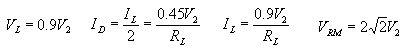
 Main parameters:
(View)
Main parameters:
(View)
View full Circuit Diagram | Comments | Reading(1219)
Electricity-saving voltage stabilizer circuit
Published:2011/6/12 22:28:00 Author:Christina | Keyword: Electricity-saving, voltage stabilizer
The electricity-saving voltage stabilizer circuit is as shown in the figure. This voltage stabilizer has the function of general delay stabilizer, the features are:(1)when the city electricity voltage is in the range of the safe voltage 220V±10%, the voltage stabilizer automaticly cuts off the power to add the city electricity to the load directly, this eliminates the power consumption of the voltage stabilizer. (2)when the city electricity voltage exceeds the safety voltage range, it will increase or decrease the voltage automatically. (3)when the load is zero, the voltage stabilizer automatically cuts off the power to eliminate the power consumption of the no-load. (4)when the input voltage is 160V to 270V, the output voltage is in the range of 220V±10%, the conforms to the state standards. The power is 2500W.
(View)
View full Circuit Diagram | Comments | Reading(4401)
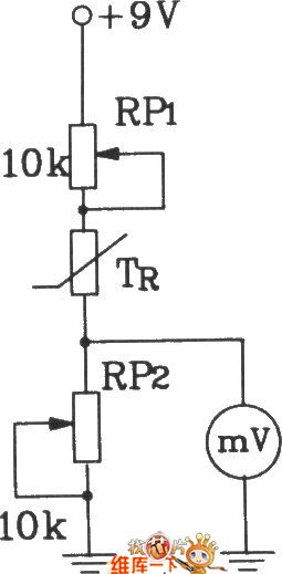
T-121 temperature sensor forming electronic thermometer circuit diagram
Published:2011/5/16 8:51:00 Author:Lena | Keyword: electronic thermometer, temperature sensor
View full Circuit Diagram | Comments | Reading(1062)
Optocoupler Switch Timing Circuit
Published:2011/5/13 21:08:00 Author: | Keyword: Optocoupler Switch, Circuit
View full Circuit Diagram | Comments | Reading(1254)
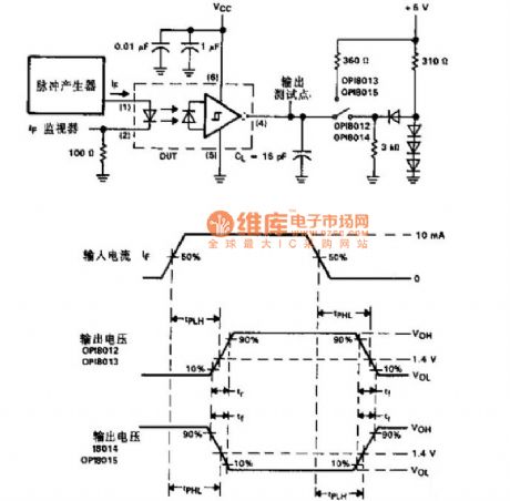
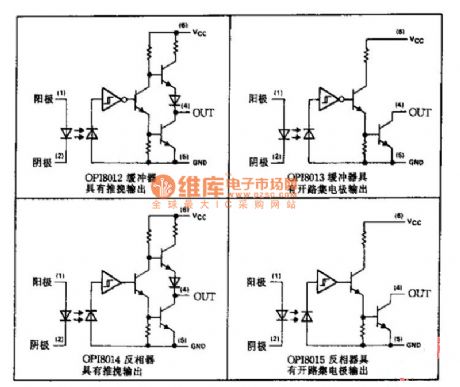
Application Circuit of Optocoupler Series
Published:2011/5/13 21:06:00 Author: | Keyword: Optocoupler Series, Application Circuit
View full Circuit Diagram | Comments | Reading(1430)
the constant voltage-driven bridge sensor circuit constituted by OP amplifier feedback loop
Published:2011/5/13 3:19:00 Author:Fiona | Keyword: constituted by OP amplifier feedback loop, the constant voltage-driven
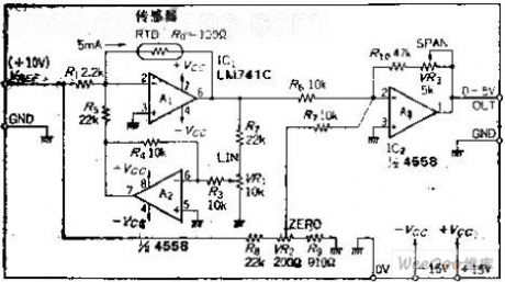
Circuit function
This is a drive, detection circuit that is suitable for use bridge sensors.It is Driven by constant voltage, the voltage is ± 2.5V, if necessary to use the IC generating reference voltage,it can also use ± 5V or ± 10V.
Circuit Work
OP amplifier A1 is a +2.5 V reference voltage generating circuit, in order to output ten mA current, adds the current enhancer TT1. If the resistance of the bridge sensor is equivalent, A2's inverting input is hypothetical, so TT2 emitter voltage should be -2.5V.
(View)
View full Circuit Diagram | Comments | Reading(1130)
Christmas fancy Lantern Circuit Of Photo-coupler
Published:2011/5/11 4:57:00 Author:chopper | Keyword: Photo-coupler, Christmass fancy Lantern
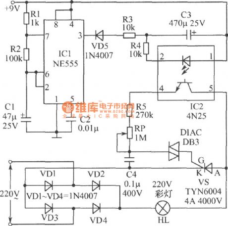
As shown in figure is an attractive Christmas fancy lantern.When the power source is available,lantern HL will brighten gradually;and it will darken automatically when it reaches the brightest level.This process is smooth.The luminance fluctuation of lantern HL depends on the charging and discharge of capacitor C3.When the output of IC1's 3 feet is high-level,capacitor C3 will discharge.And the luminance of lantern HL will decrease through photoelectric isolation of IC2(CN25).IC1 here acts as a astable oscillator,and its frequency is made by R1、R2 and C1. (View)
View full Circuit Diagram | Comments | Reading(1126)
Digit Counter Circuit
Published:2011/5/11 5:00:00 Author:chopper | Keyword: Digit Counter
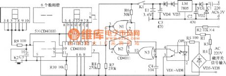
As shown in figure,the original mechanical counterjust has two magnetic switch signals terminals, while electronic counter increases input terminal c,d of AC6.3V,and thereare 4 binding posts. C1,C2,VD1,VD2 form voltage-multiplying circuit,filter circuit,and output 5V stable DC voltage after voltage stabilization,and become about 3.6V DC voltage after voltage reduction by VD3,VD4.E1 is a small Ni-cd rechargeable battery.When the mains supply is available,the supply will charge E1;and when the supply stops,E1 will charge the load to maintain the value of the counter.VD3 and VD4 here have an effect of insulation. When input magnetic switch at the both end of a,b closes,the AC 220V voltage is connected.The voltage will be converted into AC pulsating voltage after it is reduced by R1~R4 and bridgedioded by VD5~VD8.And the AC pulsating voltage provides luminotron of the photo-coupler with voltage after it is limited by R5 to make luminotron glow. The resistance of photosensitive tube will decrease because of light and generate a decline pulse,which will reverse direction through N3.And the pulse offers power to trigger of N1,N2 and N1 will output count pulse. N1,N2,N3 constitute pulse shaping circuit together. (View)
View full Circuit Diagram | Comments | Reading(1353)
The dual steady circuit of photoelectric couplers and transistors
Published:2011/6/10 21:13:00 Author:qqtang | Keyword: dual steady circuit, photoelectric couplers
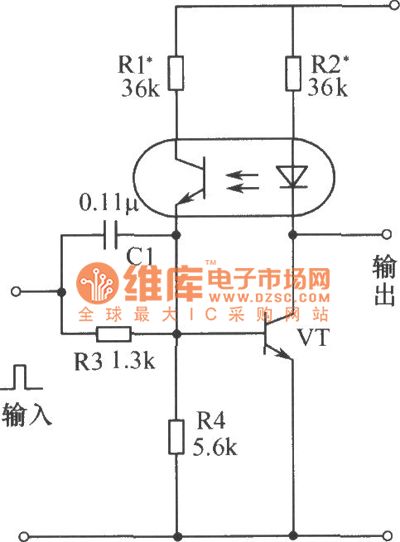
In the figure is dual steady circuit of photoelectric couplers and transistors. At the moment of power-on, the transistor VT is blocked, and the circuit outputs a high LEV. When the input pole is imposed with a positive pulse, the current in the VT collector electrode is rising, the photoelectric coupler and LED are glowing, the resistance between light dependent triodes are stepping down, as a result, the current on the basic pole of VT is increasing which forms a forward-backward feedback, and VT is saturated quickly, 1 becomes 0 . When it is input with a passive pulse, the current on VT collector electrode is reduced. (View)
View full Circuit Diagram | Comments | Reading(1229)
The photoelectric counting circuit
Published:2011/6/10 5:12:00 Author:qqtang | Keyword: photoelectric, counting circuit
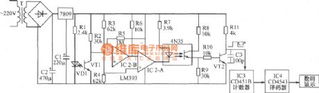
See as the figure, when thelight dependenttriode VT1 receives the infrared rays from the diode, VT1 is conducting, the inverting input terminal 6-pin of the comparator IC2-8 is in a low LEV, 7-pin outputs a high LEV which is added to the inverting terminal of the comparator IC2-A, which makes the 1-pin output a low LEV, so the lighting pipe in photocoupler 4N35 is glowing and the corresponding light dependent pipe is conducting, the triode pipe VT2 is conducting, VT2 pole outputs a low LEV. The something crosses between LED VD1 and the receiving pipe VT1, the infrared is blocked. (View)
View full Circuit Diagram | Comments | Reading(1328)
The typical application circuit of photoelectric couplers in audio amplifier circuits
Published:2011/6/10 20:09:00 Author:qqtang | Keyword: typical application circuit, photoelectric couplers, audio amplifier circuits
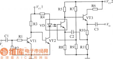
By fixing photoelectric couplers in audio amplifier circuits, not only the signals can be separated and the noise between stages can be impeded, but the audio signals can be amplified. In the circuit, photoelectric coupler can replace the audio transformer and overcome signal consumption and distortion, etc, it can also reduce the magnetic interference and the like. In the figure, VT1 and VT2 form a two-stage direct coupling amplifier circuit. The sensor or source signals are sent into the preamplifier consisting of VT1 and VT2 with the help of C1 and R1. (View)
View full Circuit Diagram | Comments | Reading(1068)
The gate circuit of photoelectric couplers
Published:2011/6/10 20:14:00 Author:qqtang | Keyword: gate circuit, photoelectric couplers
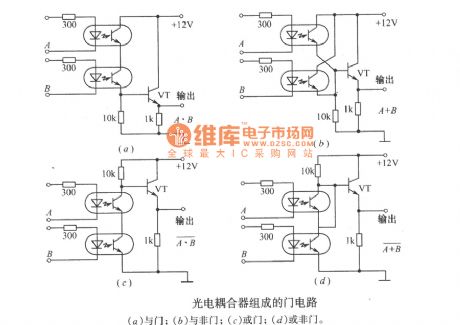
The gate circuit of photoelectric couplers(a) AND gate; (b)and NAND gate; (c)OR gate; (d) NOR gate (View)
View full Circuit Diagram | Comments | Reading(1158)
| Pages:20/27 1234567891011121314151617181920Under 20 |
Circuit Categories
power supply circuit
Amplifier Circuit
Basic Circuit
LED and Light Circuit
Sensor Circuit
Signal Processing
Electrical Equipment Circuit
Control Circuit
Remote Control Circuit
A/D-D/A Converter Circuit
Audio Circuit
Measuring and Test Circuit
Communication Circuit
Computer-Related Circuit
555 Circuit
Automotive Circuit
Repairing Circuit