
Sensor Circuit
Index 18
MOS image sensor oscilloscope imaging circuit
Published:2011/5/13 4:21:00 Author:Nicole | Keyword: MOS, image sensor, oscilloscope
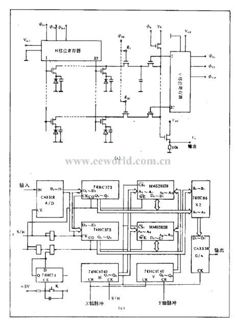
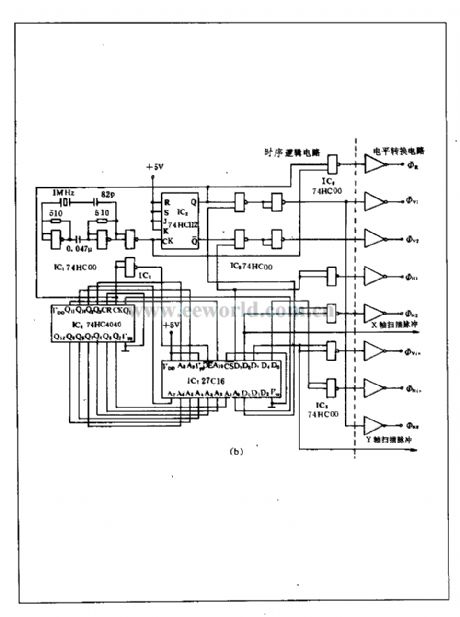
MOS image sensor is also called self scanning photodiode(SSPD), it is a solid image sensor in the late1960's. It is composed of some photodiodes, multiway MOS switch tube and scanning circuit which is integrated in a single crystal silicon. This device is divided into area array and linear array. MOS image sensor oscilloscope imaging circuit is suitable for the area devices with 32(H)×32(V) efficiency pixel. This circuit consists of temporal logic, level conversion circuit, preamplifier, sampling/maintenance and clamp circuit, A/D, D/D conversion circuit, latching storage circuit, image reduced circuit, power amplifier circuit, X, Y axis scanning circuit. The internal structure(a), surrounding drive circuit(b) and video signal processing circuit(c) are as below.
(View)
View full Circuit Diagram | Comments | Reading(1544)
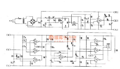
Welding Sensor Online Teaching Mode Tracking System Hardware Circuit
Published:2011/7/19 9:43:00 Author:Robert | Keyword: Welding Sensor, Online, Teaching, Tracking, System, Hardware
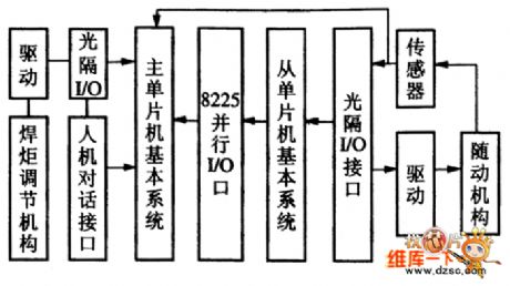
The picture shows the welding sensor online teaching mode tracking system hardware circuit. (View)
View full Circuit Diagram | Comments | Reading(826)
Infrared Sensor Control Circuit
Published:2011/7/18 10:25:00 Author:Robert | Keyword: Infrared, Sensor, Control
The picture shows the infrared sensor control circuit. (View)
View full Circuit Diagram | Comments | Reading(911)
Vortex Sensor Structure Diagram Circuit
Published:2011/7/19 9:40:00 Author:Robert | Keyword: Vortex, Sensor, Structure
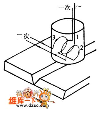
The picture shows the vortex sensor structure diagram circuit.
In the picture, the part 1 is the primary coil and the part 2 and part 3 are secondary coils. (View)
View full Circuit Diagram | Comments | Reading(949)
Welding Position Automatic Tracking Sensor Circuit
Published:2011/7/19 10:07:00 Author:Robert | Keyword: Welding, Position, Automatic, Tracking, Sensor
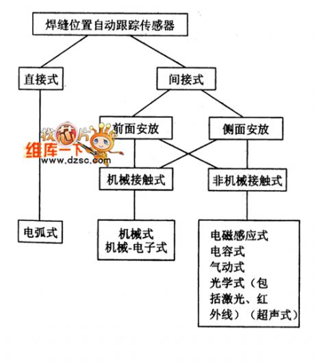
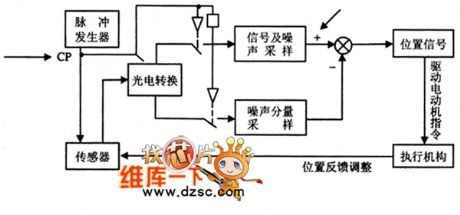
The picture shows the welding position automatic tracking sensor circuit. (View)
View full Circuit Diagram | Comments | Reading(919)
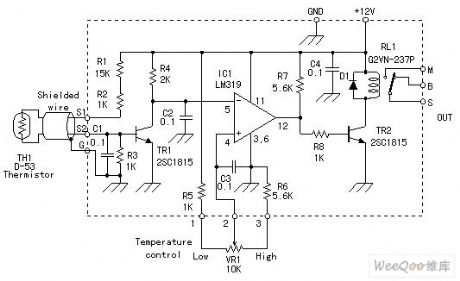
NTC Thermal Resistor Temperature Controller Circuit
Published:2011/7/15 6:14:00 Author:Sue | Keyword: Thermal Resistor, Temperature Controller
View full Circuit Diagram | Comments | Reading(2460)
Sensor Circuit 101:CO gas sensor interface circuit
Published:2011/7/13 3:55:00 Author:zj | Keyword: Sensor Circuit 101, CO gas sensor, interface circuit
View full Circuit Diagram | Comments | Reading(1412)
Digital Temperature Meter Circuit
Published:2011/7/17 8:23:00 Author:Robert | Keyword: Digital, Temperature, Meter
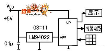
The picture shows the digital temperature meter circuit. (View)
View full Circuit Diagram | Comments | Reading(1525)
Sensor circuit 102: carbon monoxide sensor circuit
Published:2011/7/14 21:07:00 Author:zj | Keyword: Sensor circuit, carbon monoxide sensor
View full Circuit Diagram | Comments | Reading(2364)
Sensor circuit 103: Ion detector circuit
Published:2011/7/14 21:18:00 Author:zj | Keyword: Sensor circuit, Ion detector circuit
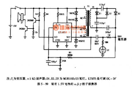
Note: T1 is transformer, *1 8Ω speaker; D1, D2, D3 are MUR1100; U1 neon. LT1073 is adjustable DC-D
Figue 5-99 α, β, γ particle detector with 1.5V battery (View)
View full Circuit Diagram | Comments | Reading(2699)
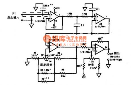
Sensor circuit figure 108: pH sensor measuring circuit
Published:2011/7/14 21:30:00 Author:zj | Keyword: Sensor circuit, pH sensor measuring
View full Circuit Diagram | Comments | Reading(1951)
Sensor circuit figure 109: pH sensor measurement compensation circuit
Published:2011/7/14 21:32:00 Author:zj | Keyword: Sensor circuit, pH sensor, measurement, compensation
View full Circuit Diagram | Comments | Reading(1488)
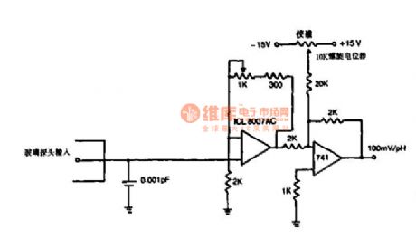
Sensor circuit figure 110: pH probe amplification circuit
Published:2011/7/14 21:34:00 Author:zj | Keyword: Sensor circuit, pH probe, amplification circuit
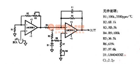
View full Circuit Diagram | Comments | Reading(2630)
Varistor circuit diagram
Published:2011/7/14 22:04:00 Author:zj | Keyword: Varistor circuit
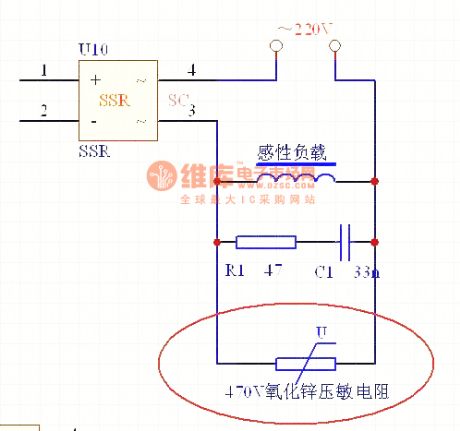
View full Circuit Diagram | Comments | Reading(3336)
Monitoring Other Voltage Circuit
Published:2011/7/16 21:14:00 Author:Robert | Keyword: Monitoring, Voltage
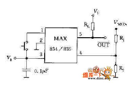
The picture shows the monitoring other voltage circuit. (View)
View full Circuit Diagram | Comments | Reading(909)
Monitoring 5V Voltage Circuit Composed Of NJM2103
Published:2011/7/16 21:20:00 Author:Robert | Keyword: Monitoring, 5V, Voltage
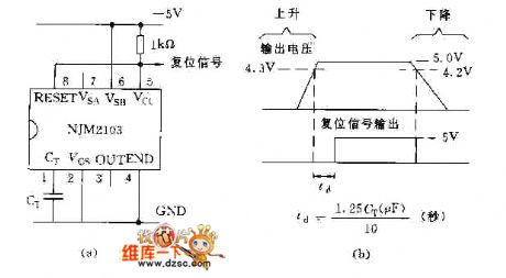
The picture shows the monitoring 5V voltage circuit composed of NJM2103. (View)
View full Circuit Diagram | Comments | Reading(1125)
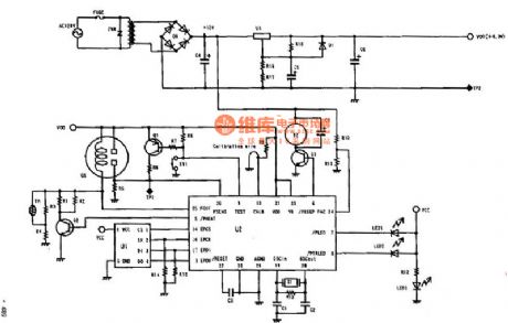
Temperature indicator
Published:2011/7/12 20:51:00 Author:zj | Keyword: Temperature indicator
View full Circuit Diagram | Comments | Reading(2357)
20 kbps light receiving circuit diagram
Published:2011/5/13 4:04:00 Author:Ecco | Keyword: 20 kbps light receiving
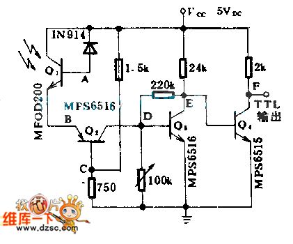
The circuit diagram uses optical transistor to drive three pieces of crystal amplifier tubes, generate TTL output, the data rate can reach 20,000 Kbp/s.
(View)
View full Circuit Diagram | Comments | Reading(1075)
Control double paper photosensitive circuit diagram
Published:2011/5/13 4:04:00 Author:Ecco | Keyword: Control double paper photosensitive
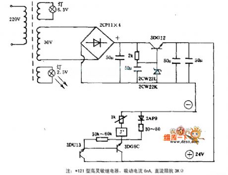
In the figure, the 6.3V and 2.5V of the transformer are served as light source for indicator light and spotlight electic bulb respectively. When the light of 3DU13 is resisted, the current can reach 8.5mA; When there's only one board to resist light , the current is 5~6mA, but at the same time, the relay still works; When there're two boards, the current is 3~4mA, the relay stops working. The mechanical action can drive 5kg iron absorption, and makes a control of a series of mechanical action, or connects to warning alarm.
(View)
View full Circuit Diagram | Comments | Reading(1317)
Touch-switch desk lamp circuit diagram
Published:2011/5/13 4:26:00 Author:Ecco | Keyword: Touch-switch, desk lamp
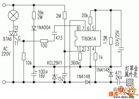
Touch-switch desk lamp circuitry is as below: It's divided into four gearsto control lamps. When it gets power and the lamp is not lit, touching the metal surface of lampshade firstly will emit the light in low brightness; touching the lamp secondly will emit proper light; touching the lamp thirdly will turn on the light absolutely, and touching the lamp fourthly will turn off the light, and the order is just like this. In the circuitry, TT6061 could be replaced by GS6061, IN4004 could be replaced by IN4007.
(View)
View full Circuit Diagram | Comments | Reading(4038)
| Pages:18/27 1234567891011121314151617181920Under 20 |
Circuit Categories
power supply circuit
Amplifier Circuit
Basic Circuit
LED and Light Circuit
Sensor Circuit
Signal Processing
Electrical Equipment Circuit
Control Circuit
Remote Control Circuit
A/D-D/A Converter Circuit
Audio Circuit
Measuring and Test Circuit
Communication Circuit
Computer-Related Circuit
555 Circuit
Automotive Circuit
Repairing Circuit