
Sensor Circuit
Index 12
FIRE_SIREN_USES_FLASHER
Published:2009/7/21 23:21:00 Author:Jessie
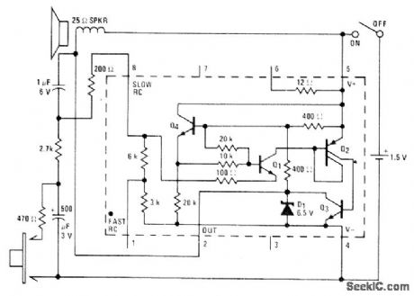
Low-drain circuit operating from 1.5-V cell uses National LM3909 flasher IC to simulate fire-alarm siren. Pressing button produces rapidly rising wail, with tone coasting down in frequency after button is released. Sound from loudspeaker resembles that of motor-driven siren. Volume is adequate for child's pedal car.-P. Lefferts, Power-Miser Flasher IC Has Many Novel Applications, EDN Magazine, March 20, 1976, p 59-66. (View)
View full Circuit Diagram | Comments | Reading(1076)
800_W_light_dimmer
Published:2009/7/22 3:38:00 Author:Jessie
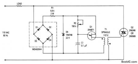
This circuit shows the basic UJT building block (Fig. 9-1) that is used to control power applied to incandescent lights. R2 varies the time constant of the timing circuit, and thus provides phase control for the triac. Power to the lights is controlled by varying the conduction angle of the triac from 0° to 170°. The power available at the 170°-conduction angle is better than 97% of that at the 180° angle. (View)
View full Circuit Diagram | Comments | Reading(0)
NOISE_SUPPRESSOR
Published:2009/7/22 1:42:00 Author:Jessie
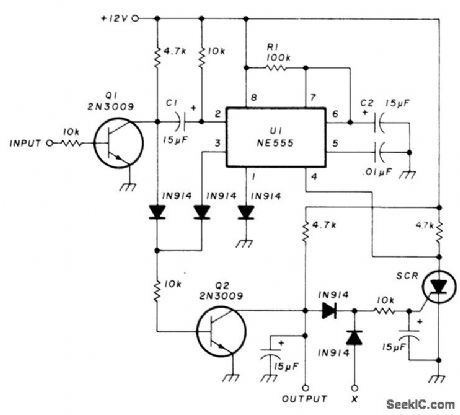
Eliminates repeater squelch tails from receiver having its own squelch, while allowing normal communications to pass through. Circuit goes between receiver squelch gate and point at which squelch acts on audio amplifier, to provide about 3-s delay before turning amplifier on. If received signal disappears before end of delay, radio remains silent and circuit resets itself. If received signal lasts longer than 3 s, as when repeater is interrogated, receiver operation is normal. Designed for receivers using low voltage level to squelch audio amplifier. NE555 timer is wired as mono MVBR that is triggered through inverter a1 each time receiver squelch is tripped, pro-vided SCR is off. SCR type is not critical. Input is taken from squelch gate in receiver.-R. K. Morrow, Jr., Repeater Kerchunk Eliminator for Mobile Rigs, Ham Radio, 0ct. 1977, p 70-71. (View)
View full Circuit Diagram | Comments | Reading(1)
Temperature_senstive_heater_control
Published:2009/7/22 3:31:00 Author:Jessie
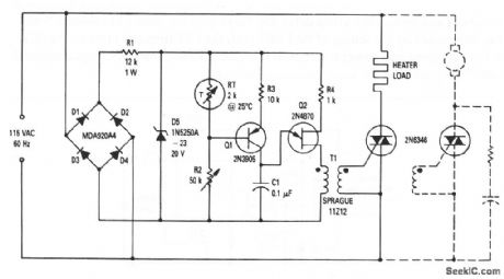
This circuit shows the basic UJT building block (Fig. 9-1) that is used to control an 800-W heater system. The simple RC circuit of Fig. 9-1 is replaced by Q1, RT and R2. Using phase control, the circuit is able to reduce power to the load as the desired temperature is reached, thus eliminating much of the overshoot inherent in mechanical controls. Although the circuit shown is for a heater, the circuit can also be used to control a constant-load motor (such as a blower motor), as indicated by the dotted portion of the diagram. The desired temperature is set by R2. The circuit can also be used for cooling by interchanging RT and R2. (View)
View full Circuit Diagram | Comments | Reading(2366)
AUDIBLE_LIGHT_SENSOR
Published:2009/7/6 6:07:00 Author:May
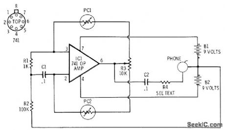
741 opamp is connected as audio oscillator with Radio Shack 276-677 photocells in feedback circuits. When light strikes PC1, its resistance decreases and frequency of audio tone in headphone decreases correspondingly. When light strikes PC2, which is connected to noninverting input of 741, increase in illumination serves to increase frequency. Choose R4 to reduce volume to desired level. R3 is balancing control for photocells.-F. M. Mims, Integrated Circuit Projects, Vol. 2, Radio Shack, Fort Worth, TX, 1977, 2nd Ed., p 81-86. (View)
View full Circuit Diagram | Comments | Reading(2094)
QUICKLY_DEACTIVATING_BATTERY_SENSOR
Published:2009/7/6 5:20:00 Author:May
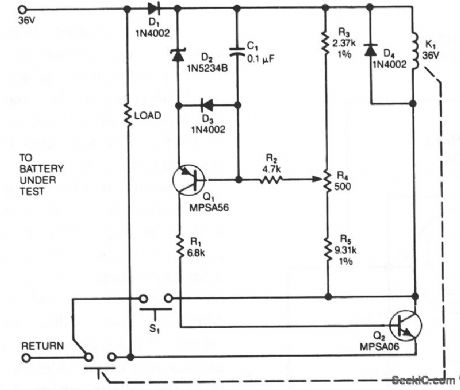
The sensing circuit rapidly disconnects the battery voltage and load whenever the voltage drops below a preset threshold. One-way operation prevents the circuit from reconnecting the load if the voltage should then rise above the threshold. C1 ensures that the circuit doesn't activate while making connections to the battery; if you accidentally reverse these connections, Dl will block the turn on the relay.
After you connect the battery, nothing happens until you depress pushbutton switch S1, which allows relay K1 to energize. When you release S1,,the relay remains on only if the battery voltage is above the minimum level. You preset this threshold-to 31.5 V when testing 36-V batteries, for example-using R4.Q1 begins to turn off as the battery voltage drops. Once the threshold level is reached, Q2 also begins to turn off, and its rising collector voltage provides positive feedback to the base of Q1, accelerating the turn off. When Q2 turns off, the relay drops out, disconnecting the battery from its load. (View)
View full Circuit Diagram | Comments | Reading(1086)
SENSITIVE_FIELD_STRENGTH_METER
Published:2009/7/6 5:09:00 Author:May
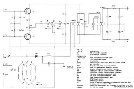
The two-pole, five-position switch, coils and 365-pF variable capacitor cover a range from 1.5 to 30 MHz. The amplifier uses Darlington npn transistors whose high beta, 5000, provides high sensitivity with S1 used as the amplifier on/off switch. Switch S2 in the left position allows the output of the 1N34 diode to be fed directly into the 50-μA meter (M) for direct reading. When S2 is in the right position, the amplifier is switched into the circuit. Switch S3 is for local or remote monitoring. At full gain setting, the input signal is adjusted to give a full-scale reading of 50 mA on the meter. Then with the amplifier switched out of the circuit, the meter reading drops down to about 0.5 mA. A 2.5-mH rf choke and capacitors C3, C4, and C5 effectively keep rf out of the amplifier circuit. (View)
View full Circuit Diagram | Comments | Reading(2364)
Low_noise_line_driver
Published:2009/7/23 21:28:00 Author:Jessie
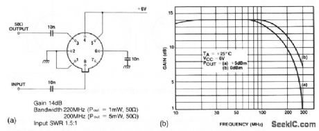
Figure 2-4A shows an SL560 used as a 50-Ω line driver. Figure 2-4B shows the typical frequency response. (View)
View full Circuit Diagram | Comments | Reading(969)
Touching Type Sensor Touching Rod Type Circuit
Published:2011/7/29 9:12:00 Author:Robert | Keyword: Touching, Sensor, Rod
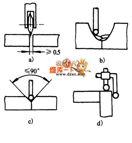
The picture shows the touching type sensor rod touching type circuit. (View)
View full Circuit Diagram | Comments | Reading(1037)
Smart Temperature Sensor MAX6698 With 7 Channels Circuit
Published:2011/7/28 6:38:00 Author:Robert | Keyword: Smart, Temperature, Sensor, 7, Channels
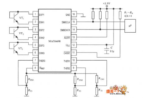
As shown, the MAX6698 could only fully connect three temperature-measuring transistors (VT1~VT3) and three thermistors (RT1~RT3). Its internal referenced voltage source UREF would supply for the three thermistors through the resistance REX1~REX3 separately. The voltage-drop would be send to pin of THER1~THER3 separately. The temperature-measuring transistor could select the CMPT3904, SST3904, KST3904-TF, SMBT3904, FMMT3904CT-ND and other types. (View)
View full Circuit Diagram | Comments | Reading(1264)
SIEPPER_MOTOR_RESPONSE_LOGIC
Published:2009/7/23 21:49:00 Author:Jessie
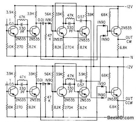
Clock-wise and counterdockwise pickoff channels each drive monostable mvbr, with output of each being added to signal of other channel. Direction-of-rotation information is supplied because pulses appear only on line whose pickoff's signal came first.-H. J Weber and M. Weiss, Analyzing Mogneticcdly Detented Stepper Servo Motors, Electronics, 33:39, p 71 -74. (View)
View full Circuit Diagram | Comments | Reading(1264)
IONIZATION_CHAMBER_SENSOR
Published:2009/7/5 22:25:00 Author:May
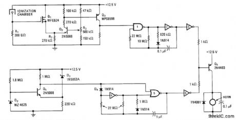
MOSFET Q1 with high input impedance monitors voltage level at divider formed by R1 and ionization chamber, with output of Q1 going to Q2 which forms other half of differential amplifier. With smoke Ievel of 2% orhigher, Q3 is tumed on and applies logic 1 to one input of NAND gate 1 in asymmetrical astable MVBR Capacitor in MVBR charges quickly and discharges slowly, making alarm hom sound during discharge via inverter 3 and driver transistor Q4 Comparator circuit Q5 drives second MVBR to energize hom through inverter 6 and same driver Q4 when battery is low, but with distinctive 1-s toot every 23 s to conserve energy remaining in battery and differentiate from fire waming.-A.Pshaenich and R. Janikowski, Gas and Smoke Detector Uses Low-Leakage MOS Transistor, Electronics, Nov. 28, 1974, p 124-125.
(View)
View full Circuit Diagram | Comments | Reading(1816)
GAS_SMOKE_SENSOR
Published:2009/7/3 5:19:00 Author:May
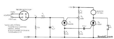
Sensor is based on selective absorption of hydrocarbons by N-type metaloxide surface. Heater in sensor burns off hydrocarbons when gas or smoke disappears, to make sensor reusable. Requires initial warmup time of about 15 min in hydrocarbon-free environment. When gas or smoke is present, VA quickly rises and triggers programmable UJT Q1. Resulting voltage pulse across R4 triggers Q2 and there by energizes buzzer. S1 is reset switch.R1 and C1 give time delay that prevents triggering by small transients such as smoke from cigarette. R5 adjusts alarm threshold. Use regulated supply.-S. J. Bepko, Gas/Smoke Detector Is Sensitive and Inexpensive, EDN Magazine, Sept. 20, 1973, p 83 and 85.
(View)
View full Circuit Diagram | Comments | Reading(1424)
SENSITIVE_LOW_COST_
Published:2009/7/2 21:15:00 Author:May

View full Circuit Diagram | Comments | Reading(1017)
CURRENT_DRAIN_SENSOR
Published:2009/7/2 2:57:00 Author:May
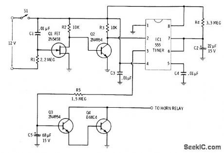
Current drawn bydome light when door is open or by ignition when turned on triggers current-sensing stages Q1 and Q2 to start 555 timer and apply power to horn relay. Initial15-s delay in sounding horn allows owner to enter car and open hidden switch S1 to deactivate alarm. If S1 is not opened during delay interval, horn sounds for about 90 s, then circuit automatically resets itself. C5 and R5 control duration of initial 15-s delay.C2 and R4 control total time that horn sounds.-R. F. Graf and G. J. Whalen, The Build-It Book of Safety Electronics, Howard W. Sams, Indianapolis, IN, 1976, p 57-62. (View)
View full Circuit Diagram | Comments | Reading(1449)
UNIDIRECTIONAL_MOTION_SENSOR
Published:2009/7/1 2:19:00 Author:May
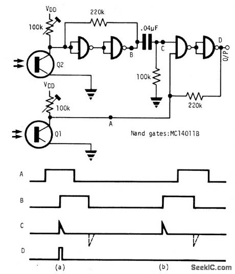
This circuit detects an object passing in one direction but ignores it going the opposite way. Two sensors define the sense of direction. The object blocks the light to phototransistor Q1 or Q2 first dependent on the direction of approach. When the object passes Q1 then Q2, an output pulse is generated at D; while no pulse is seen at D as the object passes Q2 then Q1. Object length (measured along the direction of the two sensors) should be greater than the separation of the two sensors Q1 and Q2. (View)
View full Circuit Diagram | Comments | Reading(1289)
WATER_LEVEL_SENSING_AND_CONTROL
Published:2009/7/1 1:06:00 Author:May
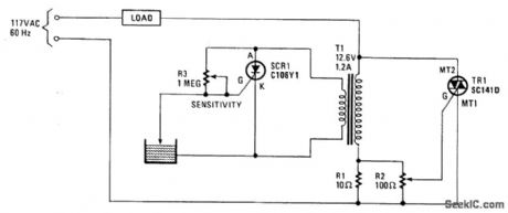
The operation of the circuit is based on the difference in the primary impedance of a transformer when its secondary is loaded and when it is open-circuit. The impedance of the primary of T1 and resistor R1 are in series with the load. The triac's gate-control voltage is developed across parallel resistors R1 and R2. When the water level is low, the probe is out of the water and SCR1 is triggered on. It conducts and imposes a heavy load on transformer T1's secondary winding. That load is reflected back into the primary, gating triac TR1 on, which energizes the load. If the load is an electric value in the water-supply line, it will open and remain open until the water rises and touches the probe, which shorts SCRl's gate and cathode, thereby turning off the SCR1, which effectively open-circuits the secondary. The open-circuit condition-when reflected back to the primary winding-removes the triac's trigger signal, thereby turning the water off. The load may range from a water valve, a relay controlling a pump supplying water for irrigation, or a solenoid valve controlling the water level in a garden lily pond. (View)
View full Circuit Diagram | Comments | Reading(1700)
RELATIVE_HUMIDITY_SENSOR_SIGNAL_CONDITIONER
Published:2009/7/1 0:50:00 Author:May
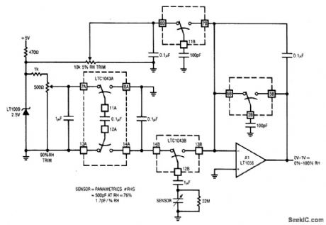
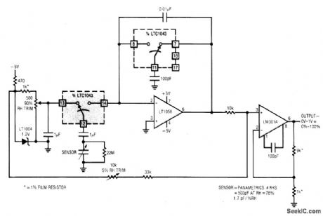
This circuit combines two LTC1043s with a based humidity transducer in a simple charge-pump based circuit. The sensor specified has a nominal 400 pF capacitance at RH = 76%, with a slope of 1.7 pF/% RH. The average voltage across this device must be zero. This provision prevents deleterious electrochemical migration in the sensor. The LTC1043A inverts a resistively scaled portion of the LT1009 reference, generating a negative potential at pin 14A. The LTC1043B alternately charges and discharges the humidity sensor via pins 12B, 13B, and 14B. With 14B and 12B connected, the sensor charges via the 1 pF unit to the negative potential at pin 14A. When the 14B-12B pair capacitor. Since the charge voltage is fixed, the average current into the summing point is determined by the sensor's humidity related value. The 1 μF value ac couples the sensor to the charge-discharge path, maintaining the required zero average voltage across the device. The 22M resistor prevents accumulation of charge, which would stop current flow. The average current into A1's summing point is balanced by packets of charge delivered by the switched-capacitor gives A1 an integrator-like response, and its output is dc. (View)
View full Circuit Diagram | Comments | Reading(2684)
BACK_BIASED_GaAsP_LED_OPERATES_AS_LIGHT_SENSOR
Published:2009/6/30 23:52:00 Author:May
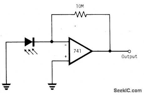
Using a simple 741 amplifier connected as a current-to-voltage converter with the LED as the current source, the voltage at the output is proportional to incident light. The junction is biased only by the difference between the summing node junction potential and ground, preventing the possibility of reverse break-down. The photon-generated current equals the short-circuit current of the junction, which is linearly related to incident light. The sensor requires a level of incident illumination that depends on the degree of opacity of the LED package. (View)
View full Circuit Diagram | Comments | Reading(3209)
CdS photoresistor for electronic metering device circuit
Published:2011/7/28 22:28:00 Author:John | Keyword: CdS photoresistor, electronic metering device
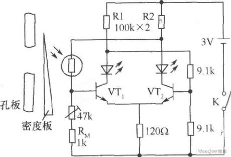
As in block cameras, CdS photoresistor can be used as electronic metering device. The light irradiation passes through the orifice in the CdS photoresistor. The MDF can be moved to achieve a balance of the circuit. When the two LED light emitting diodes are with uniform light, it is said proper to exposure. If only one lights while the other does not, it means that it is with insufficient exposure or over exposure. Thus, the MDF can be moved to achieve the correct exposure. The thermistor RM (1kΩ) in the circuit affects well for temperature compensation and compensates for error caused by temperature change of photosensitive resistor.
(View)
View full Circuit Diagram | Comments | Reading(1881)
| Pages:12/27 1234567891011121314151617181920Under 20 |
Circuit Categories
power supply circuit
Amplifier Circuit
Basic Circuit
LED and Light Circuit
Sensor Circuit
Signal Processing
Electrical Equipment Circuit
Control Circuit
Remote Control Circuit
A/D-D/A Converter Circuit
Audio Circuit
Measuring and Test Circuit
Communication Circuit
Computer-Related Circuit
555 Circuit
Automotive Circuit
Repairing Circuit