
Sensor Circuit
Index 10
SOUND_SENSOR
Published:2009/7/9 5:37:00 Author:May
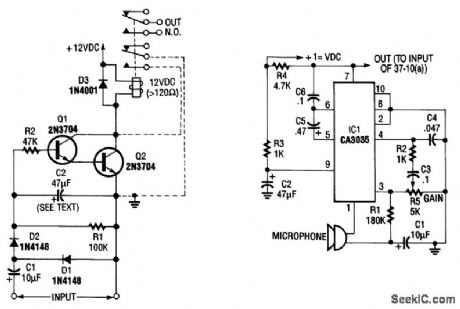
By using a microphone,high-gain amplifier(Fig.37-10(b)),and detector-relay driver(Fig.37-10(a)asound-detecting alarm system can be constructed.If you want a latching setup,make the dotted connection to the relay shown h Fig.37-10(a) (View)
View full Circuit Diagram | Comments | Reading(1823)
GROUND_FAULT_HALL_SENSOR
Published:2009/7/9 4:54:00 Author:May
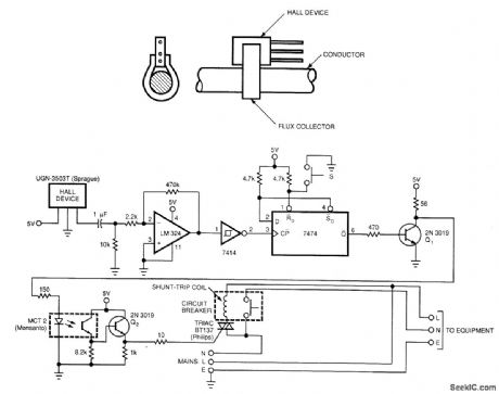
No electrical contact exists between the circuit and the conductor. The 7474 flip-flop is triggered by the output from the Hall sensor, op amp, and Schmitt trigger. This triggering activates the optocoupler, turns on the triac, and trips the circuit breaker. (View)
View full Circuit Diagram | Comments | Reading(2485)
Simple_weighing_system_with_199_pound_15_ounce_maximum_ADC1105_
Published:2009/7/20 6:01:00 Author:Jessie
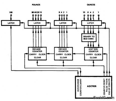
Simple weighing system with 199-pound 15-ounce maximum ADC1105 (courtesy Analog Devices, Inc). (View)
View full Circuit Diagram | Comments | Reading(954)
Water_seepage_alarm_using_an_LM3909_chip
Published:2009/7/20 6:00:00 Author:Jessie
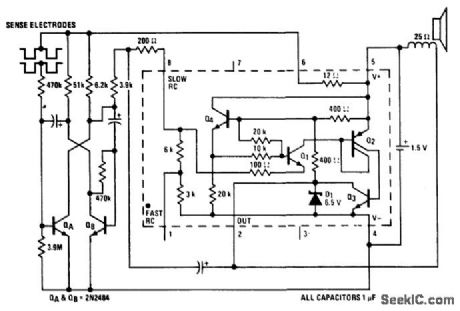
Water seepage alarm using an LM3909 chip. Circuitry inside dashed lines is the LM3909. Standby battery current drain is 100μA. The multivibrator rate is about 1 hertz when it starts and increases as more moisture passes across the sensor. The sensor should be part of the box housing the circuitry. The sensor consists of two 6-inch strips of metal about an eighth-inch apart. Stainless steel or copper will work well. Battery life for a single alkaline penlight cell is about 3 months (courtesy National Semiconductor Corporation.) (View)
View full Circuit Diagram | Comments | Reading(1139)
Programmable_mass_spectrometer_voltage_source_
Published:2009/7/20 5:58:00 Author:Jessie
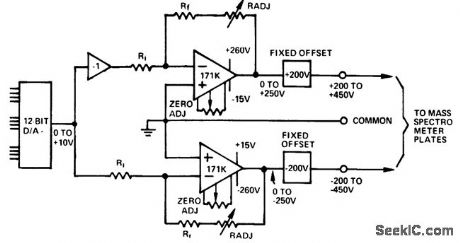
Programmable mass spectrometer voltage source (courtesy Analog Devices, Inc.). (View)
View full Circuit Diagram | Comments | Reading(1041)
Thermistor_operated_temperature_alarm_that_can_ring_a_bell_turn_on_a_light_or_ring_a_buzzer_Any_temperature_between_115°_and_165°F_can_be_detected
Published:2009/7/20 5:57:00 Author:Jessie
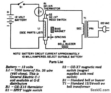
Thermistor-operated temperature alarm that can ring a bell, turn on a light or ring a buzzer. Any temperature between 115° and 165°F can be detected. To calibrate adjust the following spacings of the magnet from the coil for the indicated temperatures: 1.5 inches for 117°F, t inch for 129°F, 0.75 inch for 138°F, 0.625 inch for 149°F and 0.5 inch for 164°F. Then immerse R1 in the medium heated to the desired point to sound the alarm. Turn on 51 and adjust the bias magnet to sound the alarm. Secure the magnet (courtesy General Electric Company). (View)
View full Circuit Diagram | Comments | Reading(996)
Acoustic_thermometer
Published:2009/7/20 5:54:00 Author:Jessie
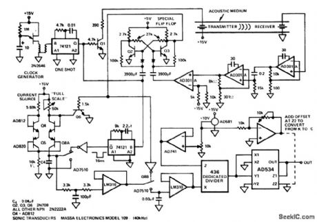
Acoustic thermometer. This circuit relies on the principle that the speed of sound varies predictably with temperature in a known medium. The sensor used is in effect a thermally dependent delay line. A40 kHz clock is used to drive a transmitting transducer (courtesy Analog Devices, Inc.). (View)
View full Circuit Diagram | Comments | Reading(2469)
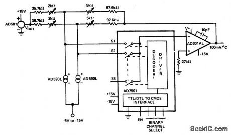
Electronic_thermometer_for_all_temperature_scales
Published:2009/7/20 6:12:00 Author:Jessie
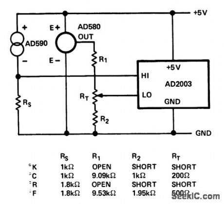
Electronic thermometer for all temperature scales (courtesy Analog Devices, Inc.). (View)
View full Circuit Diagram | Comments | Reading(1072)
8_channel_temperature_multiplexer
Published:2009/7/20 6:12:00 Author:Jessie
8-channel temperature multiplexer. An additional six temperature transducers should be added; only two are shown (courtesy Analog Devices, Inc.). (View)
View full Circuit Diagram | Comments | Reading(1105)
Temperature_differential_measurement_circuit
Published:2009/7/20 6:10:00 Author:Jessie
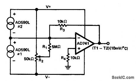
Temperature differential measurement circuit (courtesy Analog Devices, Inc.). (View)
View full Circuit Diagram | Comments | Reading(1172)
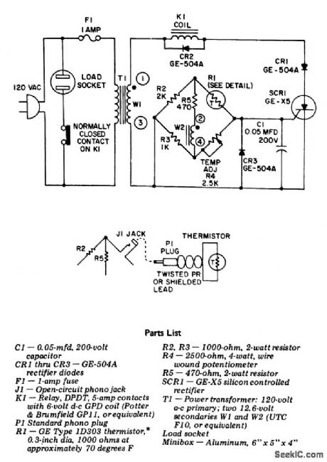
Precision_temperature_regulator_for_regulating_temperature_of_ovens_hot_plates_fluids_air_and_gases
Published:2009/7/20 6:09:00 Author:Jessie
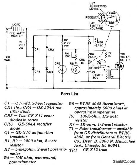
Precision temperature regulator for regulating temperature of ovens, hot plates, fluids, air and gases. It can control up to 600 watts and has adjustable gain and temperature with built-in protection against transient voltages (courtesy General Electric Company). (View)
View full Circuit Diagram | Comments | Reading(2159)
Thermistor_thermometer_that_can_be_calibrated_for_two_temperature_ranges
Published:2009/7/20 6:08:00 Author:Jessie
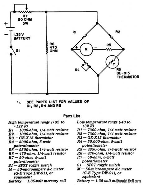
Thermistor thermometer that can be calibrated for two temperature ranges. If another meter is used in place of the one specified (1500 ohms) the resistance of M plus R5 should equal 5350 ohms. To calibrate for the 32°F to 122°F scale immerse R3 in crushed ice and adjust R4 for zero current; mark the location of R4's knob pointer. Replace R3 with the low-resistance test resistor supplied, and adjust R7 for full-scale deflection; mark R7's position. Save the low-resistance test resistor. This completes the 32°F to 122°F calibration. To calibrate for -40°F to +32°F replace R3 with the high-resistance test resistor supplied, and adjust R4 for zero current; mark R4's location. Replace the rest resistor with R3. Immerse R3 in crushed ice, and adjust R7 for full-scale deflection; mark R7's location. This completes the -40° to +32°F calibration (courtesy General Electric Company).
(View)
View full Circuit Diagram | Comments | Reading(1706)
6_channel_scanning_digital_thermometer_with_printer_output_
Published:2009/7/20 6:04:00 Author:Jessie
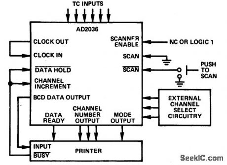
6-channel scanning digital thermometer with printer output (courtesy Analog Devices, Inc.) (View)
View full Circuit Diagram | Comments | Reading(1080)
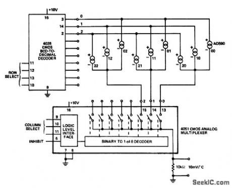
Matrix_temperature_multiplexer_
Published:2009/7/20 6:04:00 Author:Jessie
Matrix temperature multiplexer (courtesy Analog Devices, Inc.) (View)
View full Circuit Diagram | Comments | Reading(2227)
Temperature_operated_relay_for_soldering_iron_furnace_etc
Published:2009/7/20 5:52:00 Author:Jessie
Temperature-operated relay for soldering iron, furnace, etc. This circuit will control the temperature at thermistor R1 within 1°over the temperature range of 20°F to t 50°F. For other temperature ranges change R1; it should have about 1000 ohms resistance in the center of the desired control range. Pl can be substituted with other types of sensing devices (e.g., photo resistor). By using K1 to operate a large contactor heavier loads can be controlled. As is, K1 is rated for 5 amperes (courtesy General Electric Company). (View)
View full Circuit Diagram | Comments | Reading(2258)
Light_intensity_absorbance_circuit_using_the_757N_log_ratio_module_and_the_AD2009_3_1_2_digit_DPM
Published:2009/7/20 5:49:00 Author:Jessie
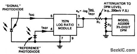
Light intensity absorbance circuit using the 757N log ratio module and the AD2009 3 1/2-digit DPM (courtesy Analog Devices, Inc.). (View)
View full Circuit Diagram | Comments | Reading(1048)
Phasemeter_for_sinusoidal_signals
Published:2009/7/20 5:47:00 Author:Jessie
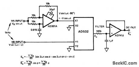
Phasemeter for sinusoidal signals. This circuit provides a good linear measure of phase for small angles up to 14° and a sinusoidal measure of angles between +90°and -90°(courtesy Analog Devices, Inc.). (View)
View full Circuit Diagram | Comments | Reading(1111)
Electronic_thermostat
Published:2009/7/20 5:45:00 Author:Jessie
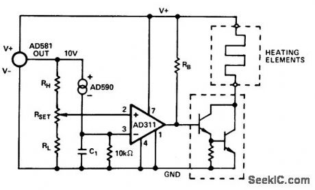
Electronic thermostat (courtesy Analog Devices, Inc.). (View)
View full Circuit Diagram | Comments | Reading(0)
Automatic_liquid_level_control_for_sump_pumps_water_storage_tanks_swimming_pools_animal_drinking_troughs_etc
Published:2009/7/20 5:44:00 Author:Jessie
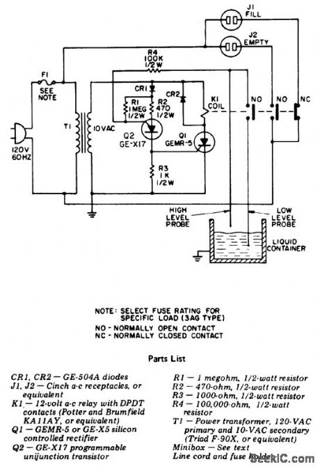
Automatic liquid-level control for sump pumps, water storage tanks, swimming pools, animal drinking troughs, etc. This device can operate equipment to keep the liquid level between two prescribed points (courtesy General Electric Company). (View)
View full Circuit Diagram | Comments | Reading(2244)
LATCHING_WATER_SENSOR
Published:2009/7/9 3:09:00 Author:May
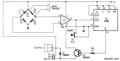
A balanced Wheatstone bridge controls a JK flip-flop that uses an op amp as an interface. This in turn drives a relay circuit. R1 through R4 can be made larger for increased sensitivity. (View)
View full Circuit Diagram | Comments | Reading(1928)
| Pages:10/27 1234567891011121314151617181920Under 20 |
Circuit Categories
power supply circuit
Amplifier Circuit
Basic Circuit
LED and Light Circuit
Sensor Circuit
Signal Processing
Electrical Equipment Circuit
Control Circuit
Remote Control Circuit
A/D-D/A Converter Circuit
Audio Circuit
Measuring and Test Circuit
Communication Circuit
Computer-Related Circuit
555 Circuit
Automotive Circuit
Repairing Circuit