
Sensor Circuit
Index 17
Sensor detector circuit diagram
Published:2011/7/20 20:08:00 Author:Ecco | Keyword: Sensor detector
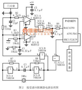
Figure 1 shows the the proximity sensor detector circuit temperature compensation which is composed of MAX912. In the circuit, the door lock (or 200cm2 Bonded Copper) is used as a capacitor plate composed of a sensing surface. When the body is approached the other plate, the capacitance value will increase with the closing of the body (range between 2pF to 5pF). When the body is 20cm far away from the door lock, it can generate approximately 2pF capacitance. The 74HC04 and crystal oscillator will generate 1MHz square wave signal, which is all the way sent to the microcontroller PIC16C71 as the oscillation signal; another way is sent to the proximity sensor detector circuit.
(View)
View full Circuit Diagram | Comments | Reading(1404)
ION_SENSING_ELECTROSCOPE
Published:2009/6/19 4:57:00 Author:May
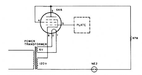
Negative ions are sensed by a plate antenna. A negative charge induced on the plate cuts off a vacuum tube, causing the neon indicator to go out. (View)
View full Circuit Diagram | Comments | Reading(1063)
INTERFACING_RESISTIVE_TRANSDUCERS
Published:2009/6/19 4:44:00 Author:May

All types of resistive-element transducers, such as servo-pots, level indicators, thermistors, photosensors, strain gages, and so on, can be directly connected to the AD537. The scale-correction factor, K, is a function of resistance, varying from 0.65 to 0.98 for values from 3 to 100 kΩ. (View)
View full Circuit Diagram | Comments | Reading(1344)
Call finder circuit
Published:2011/7/18 20:56:00 Author:zj | Keyword: Call finder
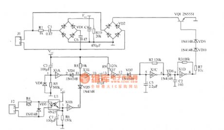
The work principle of the circuit: in the circuit, J1 is connected to the telephone line. When there is no call in, Vcc is 0V for there is no ringing signal. The circuit does not work with no power source voltage. When there is call in, the ringing signal is current limited by the R1, through C1, C6 coupling, bridge VD1 rectifier, C4 filter to supply power voltage Vcc for the whole device. By detecting, Vcc changes from 1.8V to 4.2V with ringing signal, but it does not affect the function. (View)
View full Circuit Diagram | Comments | Reading(1020)
STRAIN_GAGE_SENSOR
Published:2009/6/19 1:46:00 Author:May
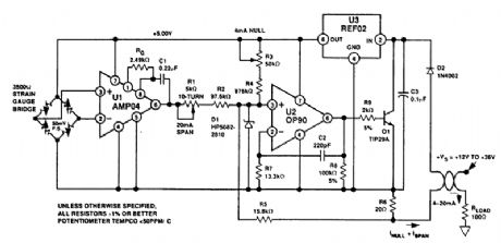
In this loop-powered strain-gage sensor application, a 50-mV full-scale(FS)bridge output is amplified and calibrated for a 4-20-mA transmitter output. Power is fumished by the remote loop sup-ply of 12 to 36 V. (View)
View full Circuit Diagram | Comments | Reading(3178)
SINGLE_PLATE_TOUCH_SENSOR
Published:2009/6/18 4:34:00 Author:May
This system operates on the principle that capacitance loading of an oscillator will lower its fre-quency. When a foreign body comes into contact with touch plate, the frequency of U1 is lowered.This removes the oscillator signal from U1 from U2's passband, which causes U2 to lose lock, turns off the LED, and causes the colle,ctor of Q1 to go low. (View)
View full Circuit Diagram | Comments | Reading(1251)
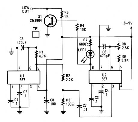
BRIDGING_TOUCH_PLATE_SENSOR__
Published:2009/6/18 4:03:00 Author:May

In this circuit, two 567 tone decoders are used. One is an oscillator, the other is a detector.Bridging TP1 and TP2 causes U2 to receive UI's signal, which causes pin 8 of U2 to go low. This ac-tion lights LED1 and drives the output of Q2 high. (View)
View full Circuit Diagram | Comments | Reading(1693)
MAGNETIC_PROXIMITY_SENSOR
Published:2009/6/17 22:05:00 Author:May
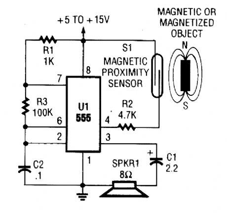
A magnetic need switch enables a 555 osciltator, which drives a speaker. C2 can be varied for different tone frequencies. (View)
View full Circuit Diagram | Comments | Reading(1888)
ELECTROMAGNETIC_FIELD_SENSOR
Published:2009/6/17 22:05:00 Author:May
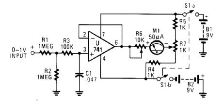

A telephone pick-up coil is used as a sensing coil. Any 60-Hz hum picked up by the sensing coil is rectified, amplified, and detected, and then drives a meter. (View)
View full Circuit Diagram | Comments | Reading(2659)
PHOTOELECTRIC_SENSOR
Published:2009/6/17 2:37:00 Author:May
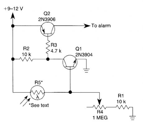
The circuit can be used as a sensor that can trigger an alarm without direct contact being madeby the intruder In this circuit,a visible or invisible tight Source radiates on the sensor,keeping thedetection loop In what could essentially be called a normally closed condition
As long as the light source striking R5 remalns uninterrupted,the switch remalns closed But ifan intruder passes between the light Source and the sensor,the circuit goes from closed to open,andtriggers the alarm.
A light-dependent resistor(LDR), whose resistance varles inversely in with the amount of lighthitting its sensitive surface,is used A bright light aimed at R5 causes its internal resistance to dropas low as a few hundred ohms;In total darkness,the unit’s resistance can rlse to several megohmsThe light-dependent resistor(R5) is conrtected between the +V supply and the base of Q1.As longas R5 detects light,it supplies ample base current to cause Q1's collector to saturate to near groundlevel That also pulls the base of Q2(a 2N3906 genera-purpose pnp transistor) to near ground level,turning it on and clamping its collector to the+V rail. (View)
View full Circuit Diagram | Comments | Reading(2762)
LIGHT_DEPENDENT_SENSOR_FOR_MULTIPLE_INPUTS
Published:2009/6/17 2:22:00 Author:May
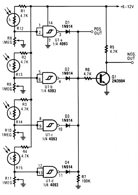
This light-dependent sensor uses LDRs to detect the presence or absence of light. As long as the light source striking the LDRs remains constant, the alarm does not sound. But when the light is interrupted, the alarm is triggered. (View)
View full Circuit Diagram | Comments | Reading(1206)
SIMULATED_INDUCTOR
Published:2009/6/16 2:25:00 Author:May
View full Circuit Diagram | Comments | Reading(1)
voltage control oscillator circuit composed of LH0042
Published:2011/7/18 22:31:00 Author:zj | Keyword: voltage control, oscillator circuit
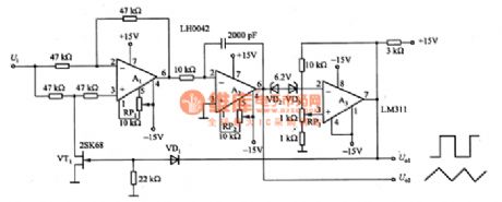
This diagram is voltage controlled oscillator circuit composed of LH0042. In the circuit, A1 is a voltage follower and inverter converter circuit. It provides an integrator equal in absolute values, opposite polarity voltage for A2; A2 is common integrator circuit; A3 exerts a positive feedback, with a comparator and a trigger role; VT1 can be used to do simulation switch, selecting 2SK68 FET, the on-resistance RON is about 100 ohms, and compared to the 47k ohm resistance which is connected with A1 input end, the error is about 0. 2%.
(View)
View full Circuit Diagram | Comments | Reading(1227)
Voltage control oscillator circuit composed of μA709
Published:2011/7/17 21:11:00 Author:zj | Keyword: Voltage control, oscillator circuit
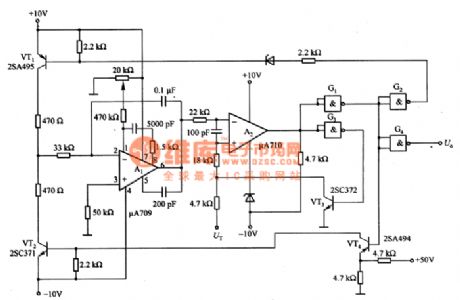
This circuitis a voltage control oscillator circuit composed of μA709. In a circuit,VT1 and VT2can consist of the driving switch circuit;A1 can form Miller integral circuit ; A2 and G1 ~ G3 can constitute a backlash adjustable level comparator circuit. The output of the A2 through the G3 and VT3 are fed to the non-inverting input end to form a positive feedback loop, which constitutes a bistable characteristics of hysteresis comparator circuit.
(View)
View full Circuit Diagram | Comments | Reading(1600)
Photoelectric Sensor Of Tracking White Line Circuit
Published:2011/7/26 4:59:00 Author:Robert | Keyword: Photoelectric Sensor, Tracking, White, Line
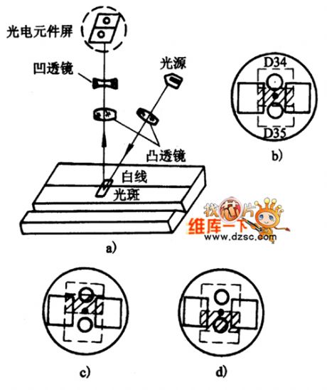
The picture shows the photoelectric sensor of tracking white line circuit.
Part (a)shows the diagram. Part (b)shows themiddle line. Part (c) shows the left-deviation line. Part (d) shows the right-deviation line. (View)
View full Circuit Diagram | Comments | Reading(1076)
Eddy Current Sensor Principle Circuit
Published:2011/7/20 9:27:00 Author:Robert | Keyword: Eddy Current, Sensor, Principle
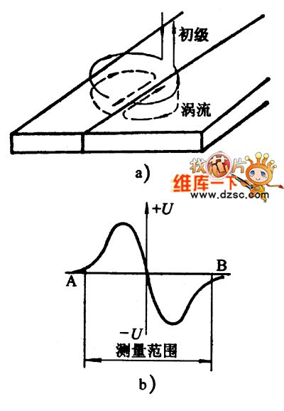
The picture shows the eddy current sensor principle circuit.
The pictureshows theeddy current distribution. The picture b shows the sensitivity curve. The U is signal voltage. (View)
View full Circuit Diagram | Comments | Reading(1479)
Electronic Sensor Principle Circuit
Published:2011/7/20 9:23:00 Author:Robert | Keyword: Electronic, Sensor, Principle
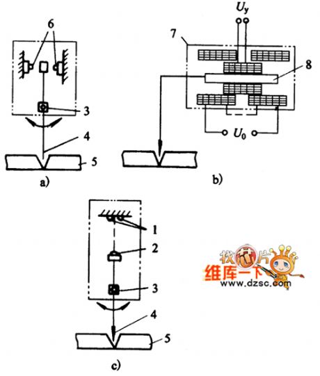
The picture shows the electronic sensor principle circuit.
The picture a is mechanical-switching type. The picture b is mechanical-differential transformer type. The picture c is mechanical-optical type.
The part 1 is photoelectric tube. The part 2 is LED. The part 3 is lever axis. The part 4 is tracking probe. The part 5 is workpiece. The part 6 is micro switch. The part 7 is displacement sensor. The part 8 is iron core. (View)
View full Circuit Diagram | Comments | Reading(1098)
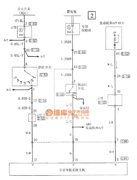
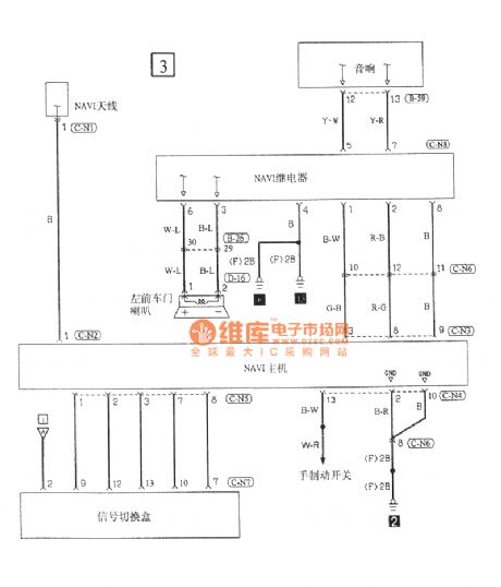
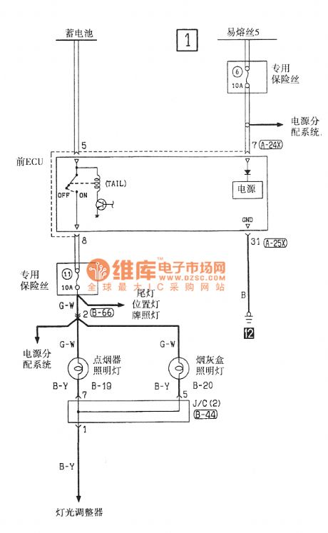
Southeast Ling Sheng navigation electric system circuit
Published:2011/7/20 21:15:00 Author:leo | Keyword: Navigation, electric system
View full Circuit Diagram | Comments | Reading(921)
High sensitivity sound snoop device
Published:2011/7/17 20:25:00 Author:zj | Keyword: High sensitivity, sound snoop device
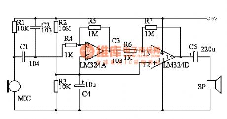
Working principle
The circuit is shown above.Microphone which is put in a special bobbinrecieves sound from certain direction(Other directions are inhibited). Sound is sent into amplifier. The amplifier is composed of two poles. Using it you can hear weak sound from far away.LM324 is integrated by four operational amplifier. Here just uses A&D. The connection method can refer to the diagram. (View)
View full Circuit Diagram | Comments | Reading(2780)
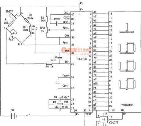
ICL7106 constitutes a micropower thermometer
Published:2011/7/20 2:38:00 Author:zj | Keyword: micropower thermometer
View full Circuit Diagram | Comments | Reading(6107)
| Pages:17/27 1234567891011121314151617181920Under 20 |
Circuit Categories
power supply circuit
Amplifier Circuit
Basic Circuit
LED and Light Circuit
Sensor Circuit
Signal Processing
Electrical Equipment Circuit
Control Circuit
Remote Control Circuit
A/D-D/A Converter Circuit
Audio Circuit
Measuring and Test Circuit
Communication Circuit
Computer-Related Circuit
555 Circuit
Automotive Circuit
Repairing Circuit