
Sensor Circuit
Index 9
TRANSISTOR_SENSOR_TEMPERATURE_MEASURER
Published:2009/7/11 0:34:00 Author:May
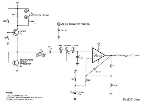
Using the fact that the I/BE of a transistor shifts 59.16 mV per decade of current at 25℃. This constant is 0.33%/'℃. This VBE-vs.-current relationship holds true regardless of the VBE absolute value. IC, an LT1043, acts as an oscillator and switches a current source (Q1) at a 10:1 ratio. The stepped 10:1 current drive is translated to temperature by IC2, Q2, and the associated components. Accuracy is 11%. No compensation is needed if Q2 is changed. (View)
View full Circuit Diagram | Comments | Reading(1593)
TEMPERATURE_SENSOR
Published:2009/7/11 0:31:00 Author:May
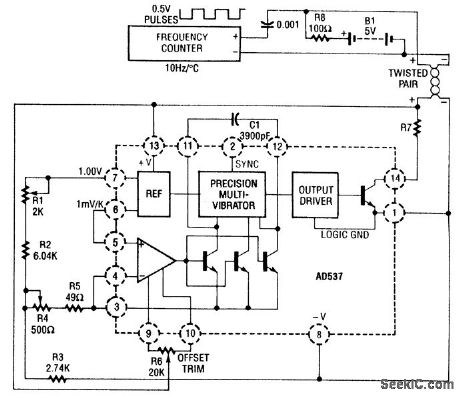
The AD537 uses its two reference outputs-one fixed at 1 V, the other of which varies with tempera-ture (1 mV per °K). At 0℃, the 1-V reference multiplied by 0.273 will balance this voltage and produce a zero output. The scale in this circuit is 10 Hz/℃. Output from, as well as power to, the circuit, is fed via a two-wire twisted pair. A frequency counter is used as a readout. (View)
View full Circuit Diagram | Comments | Reading(0)
BRIDGE_TYPE_SENSOR
Published:2009/7/10 22:56:00 Author:May
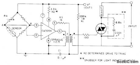
CA3094 programmable opamp is connected as level-triggered MVBR at output of bridge, driving triac for temperature monitor or control applications. Sensor can be any temperatu re-depend ent device. Load can be lamp, horn, or bell. For control applications, load is appropriate temperature-controlling device connected in feedback relationship to sensor.- Circuit Ideas for RCA Linear 'ICs, RCA Solid State Division, Somerville, NJ, 1977, p 10. (View)
View full Circuit Diagram | Comments | Reading(1288)
DIFFERENTIAL_TEMPERATURE_SENSOR
Published:2009/7/10 22:40:00 Author:May

Respands to difference in temperatures of MTS102 silicon high-precision temperature sensors having range of-40℃ to+150℃ With both sensors at same temperature,100K pot is adjusted so utputvo voltage is 0.000 V.Opamptypes are not crjtio al R1 is 27K for measurements in Celsius or kelvin and 15K for Fahrenheit measurements.- Silicon Temperature Sensors, Motorola,Phoenix,AZ,1978,DS 2536 (View)
View full Circuit Diagram | Comments | Reading(2711)
POSITION_SENSOR
Published:2009/7/10 22:07:00 Author:May

Position of small heating element sliding inside thin-wall brass tube is sensed by National LX5700 temperature transducer mounted outside of tube, With heater at center, transducers at both ends reach same temperature. With heater at one end of pipe, that transducer is about 50℃ above ambient and other is near ambient. As heater moves toward one end, one thermometer becomes more sensitive and the other less. Circuit regulates heater power to keep position gain constant. Digital voltmeter gives average position. Applications include measuring average truck spring deflection while moving on rough road.-P. Lefferts, A New Interfacing Concept; the Mono-Iithic Temperature Transducer, National Semiconductor, Santa Clara, CA, 1975, AN-132, p 9. (View)
View full Circuit Diagram | Comments | Reading(1613)
MATCHED_TRANSISTOB_SENSOR
Published:2009/7/10 21:35:00 Author:May
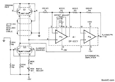
Precision Monolithics MAT-01H matched-tlansistor pair Q1 senses temperature over range of -55℃ to +125℃ with inherent linearity and long-term stability. Matched transistors Q2 (MAT-01GH) are current sources for sensing transistors. Transistol combination provides diffelential voltage output that is directly proportional to absol ute temperatu re. Amplifier using OP-10CY changes this voltage difference to single-ended signalthatcan be used for measurement orcontrol. Circuit will drive 10-V full-scale digital panel meter to give digital thermometer.-J. Simmons and D. Soderquist, Temperature Measurement Method Based on Matched Tran-sistor Pair Requires No Reference, Precision MonolithIcs, Santa Clara, CA, 1975, AN-12, p 4. (View)
View full Circuit Diagram | Comments | Reading(1192)
TRANSISTOR_SENSOR_1
Published:2009/7/10 21:17:00 Author:May
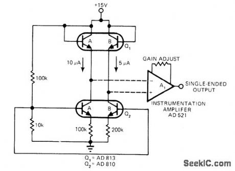
Current-ratio differential-pair temperature sensor uses dual transistor Q1. Difference between base-emitter voltages of Q1A and Q1B varies linearly with temperature, when dual transistor Q2 provides 10μA through Q1A and 5μA through Q1B. Instru-mentation opamp provides single-ended output with better than 1℃ accuracy over 300℃ temperature range. Analog Devices AD 590 IC version of differential pairwill operate overwire line thousands of feet away from instrumentation opamp, for remote sensing.-J, Williams, Designer's Guide to: Temperature Sensing, EDN Magazine, May 5, 1977, p 77-84. (View)
View full Circuit Diagram | Comments | Reading(2766)
FULLY_LINEAR_DIODE_SENSOR_
Published:2009/7/10 20:53:00 Author:May
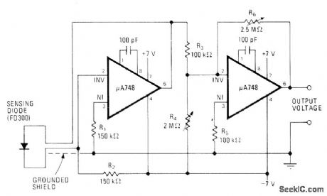
First opamp acts as constant-current source for temperature-sensing diode, making voltage drop across diode depend only on temperature. Second opamp offsets diode voltage to whatever temperature range is desired and provides gain that is adjustable with R6. R4, is used to set output at zero for selected temperature such as for 0℃. Circuit can then be adjusted to give 1 V at 50℃.-C. J. Koch, Diode or Transistor Makes Fully Linear Thermometer, Electronics, May 13, 1976, p 110-112. (View)
View full Circuit Diagram | Comments | Reading(1622)
HIGH_GAIN_CURRENT_SENSOR
Published:2009/7/10 4:11:00 Author:May
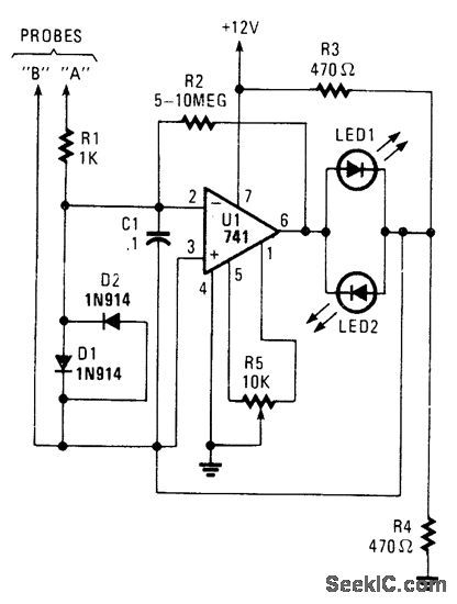
A high-gain amplifter using a UA741 is used to sense relative voltage drop in a conductor, and therefore current in the conductor. R2 can be increased to 10 MΩ for increased sensitivity. LEDt and LED2 provide polarity indication. This circuit can be used to detect current flowing in a PC board trace, and also for locating shorts and opens. (View)
View full Circuit Diagram | Comments | Reading(1616)
Multiplexed_temperature_sensors
Published:2009/7/19 22:10:00 Author:Jessie
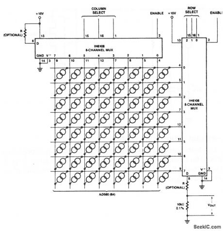
This circuit shows 64 AD590 transducers that are connected as multiplexed temperature sensors. A 6-bit digital word selects one of the 64 sensors (each at a different location, as desired). Harris Semiconductors Data Acquisition 1991 p 12-s (View)
View full Circuit Diagram | Comments | Reading(1120)
Average_temperature_sensor
Published:2009/7/19 22:06:00 Author:Jessie
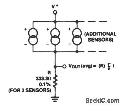
This circuit shows an AD590 connected as an average-temperature sensor. The sum of the AD590 currents appears across R, which is chosen by R = (10 kΩ)/n, where n = the number of sensors. Harris Semiconductors, Data Acquisition 1991 p 12-7 (View)
View full Circuit Diagram | Comments | Reading(1165)
Lowest_temperature_sensor
Published:2009/7/19 22:06:00 Author:Jessie
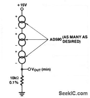
This circuit shows an AD590 connected as a lowest-temperature sensor. The available current is that of the coldest sensor.Harris Semiconductors, Data Acquisition 1991 p 12-7 (View)
View full Circuit Diagram | Comments | Reading(928)
Absolute_temperature_sensor
Published:2009/7/19 22:03:00 Author:Jessie
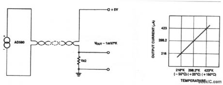
This circuit shows an AD590 that is connected as a basic absolute-temperature sensor. The output is proportional to absolute temperature, as shown by the graph. Harris Semiconductors Data Acquisition 1991, p 12-7 (View)
View full Circuit Diagram | Comments | Reading(1096)
OPTICAL_INTERRUPTION_SENSOR
Published:2009/7/10 1:34:00 Author:May
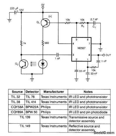
Using only an 8-pin IC and a few discrete components, you can build the infrared optical interrupter. The NE567 tone decoder has all the necessary circuit elements: a local oscillator, a PLL decoder, and a 100-mA output-drive capability. The local oscillator, which is tuned to 40 kHz by RT and CT, drives Q1, a universal low-power silicon pnp transistor (such as a 2N3906, BC559, or ZTX500). Q1 drives the IR-emit-ting diode. The receiving part of the circuit surrounds the IC's internal PLL input at pin 3. When the pho-todetector, Q2, detects the oscillating IR light beam, the 40-kHz signal appears at pin 3 of the IC. Under this condition, the circuit locks and the IC's output is high. When something opaque comes between the LED and Q2, the 40-kHz signal doesn't reach the PLL input, and the IC's output goes low.
The feedback network between pins 1 and 8 prevents the output from chattering. If you connect this circuit to a high-inertia load (such as a mechanical relay), the output doesn't tend to oscillate and you can eliminate these feedback components. The circuit works with virtually any LED-Photodetector pair, but matched pairs allow for longer distances between the emitter and receiver. The table lists some of the best choices. (View)
View full Circuit Diagram | Comments | Reading(3699)
SIMPLIFIED_VOLTAGE-LEVEL_SENSOR
Published:2009/7/9 23:18:00 Author:May
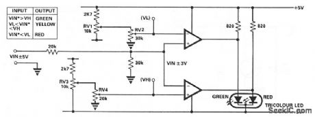
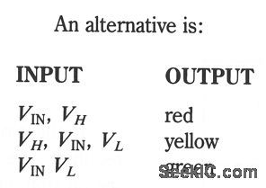
This circuit uses only one IC, either 1, LM393 dual comparator or 1/2, LM339 quad comparator. RV1 and RV3 set the full scale reference voltage, and RV2 and RV4 set the switching thresholds to a value between 0 V and the full-scale reference. The change in input voltage needed to fully switch the output state is less than 0.05 mV (typical). (View)
View full Circuit Diagram | Comments | Reading(1462)
LIGHTS_ON_SENSOR
Published:2009/7/9 22:56:00 Author:May
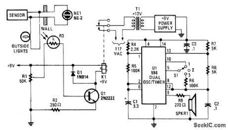
Remote monitoring of a light source is possible with this circuit.Photocell R3 activates Q1 and relay K1. U1 is a tone generator that drives a small speaker. (View)
View full Circuit Diagram | Comments | Reading(1167)
DATA_LINE_REMOTE_SHORT_SENSOR
Published:2009/7/9 22:54:00 Author:May
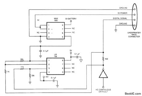
Sensing short circuits in equipment that performs under water is especially critical, but Fig. 20-4's wet-mate connector design also suits other remote short-circuit sensing applications. Because of the limits imposed by the battery and voltage levels, the circuit uses the data line to sense short circuits.
The differential voltage that develops across the 422-Ω resistor in the data line drives a low-bandwidth op amp, which amplifies and filters the differential signal. The resistor values produce a gain of 3. The op amp's output controls the voltage regulator's shutdown pin.
To operate correctly, the circuit must have a continuous stream of digital data. Under normal conditions, and using high-speed CMOS logic, the data source sinks less than 10 μA. This normal operation generates about -3 mV across the sense resistor. The op amp's output will be slightly negative, producing a solid ON signal to the voltage-regulator chip. When a short occurs, the resistor and op amp together produce an average of 2.4 Vdc. This voltage provides a solid OFF to the voltage-regulator chip.
The peak signal-line current is about 12 mA (5-V data divided by 422 Ω), which HCMOS logic can handle. The addition of the resistor and op amp only changes the rise time to about 40 ns and doesn't cause any problems with the 2.5-MHz data rate. When the short is no longer present, the voltage regulator chip turns on again. You can use the same circuit with any TTL on/off-type voltage-regulator IC. (View)
View full Circuit Diagram | Comments | Reading(1155)
INTEGRATOR_RAMP_GENERATOR_WITH_INITIAL_CONDITION_RESET
Published:2009/7/9 21:59:00 Author:May
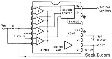
Channel 1 is wired as a conventional integrator, and channel 2 as a voltage follower. When channel 2 is switched on, the output will follow VIN and C will discharge to maintain 0 V across it. When channel 1 is then switched on, the output will initially be at the instantaneous value of VIN, and then will commence integrating towards the opposite polarity. This circuit is particularly suitable for timing ramp generation using a fixed dc input. Many variations, such as building programmable time constant integrators, are possible. (View)
View full Circuit Diagram | Comments | Reading(1481)
PROXIMITY_SENSOR
Published:2009/7/9 21:40:00 Author:May
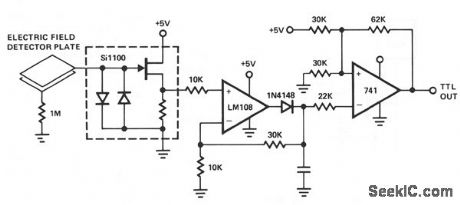
The Si1100 series circuit input is connected to a capacitive field sensor-possibly a piece of doublesided circuit board. Any induced voltage change on the plate is fed to the input of the peak detector section of the op-amp circuit. The Schmitt trigger monitors the voltage across the capacitor and changes its output state when the capacitor voltage crossed the 2.5-trigger point. The output from the Schmitt trigger switches between 0 and 5 V and is microprocessor compatible for sensor applications, such as computer-controlled intruder alarms. (View)
View full Circuit Diagram | Comments | Reading(2603)
RELAY_OUTPUT_PROXIMITY_SENSOR
Published:2009/7/9 20:53:00 Author:May
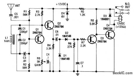
Q1 is used as an oscillator around 300 kHz. R9 is set so that the oscillator just begins to run. An object near the antenna will load the circuit down, and stop the oscillations. This is detected by bufferQ2,diodes D1 and D2, and this activates relay driver Q4, which operates the relay. (View)
View full Circuit Diagram | Comments | Reading(2420)
| Pages:9/27 1234567891011121314151617181920Under 20 |
Circuit Categories
power supply circuit
Amplifier Circuit
Basic Circuit
LED and Light Circuit
Sensor Circuit
Signal Processing
Electrical Equipment Circuit
Control Circuit
Remote Control Circuit
A/D-D/A Converter Circuit
Audio Circuit
Measuring and Test Circuit
Communication Circuit
Computer-Related Circuit
555 Circuit
Automotive Circuit
Repairing Circuit