
Sensor Circuit
Index 11
LIQUID_LEVEL_SENSOR
Published:2009/7/9 2:49:00 Author:May
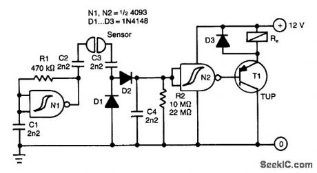
This circuit uses an ac-sensing signal to elimi-nate electrolytic corrosion. The ac signal is rectifted and used to drive a transistor that controls a relay. (View)
View full Circuit Diagram | Comments | Reading(1518)
LIGHT_SOURCE_STABILIZER
Published:2009/7/20 11:50:00 Author:Jessie
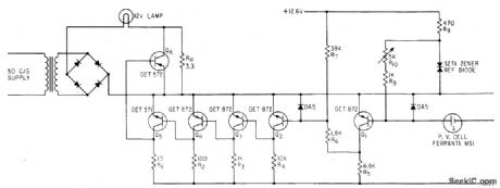
Feedback circuit generates precise pulses to control light level of photoelectric light source. Difference between reference current supplied by zener diode and current from photocell is amplified by transistor chain and applied to Q6 to adjust lamp current.-J. R. Dyke, Illumination Stabilizer for Photosensing System, Electronics, 34:52, p 44-45. (View)
View full Circuit Diagram | Comments | Reading(1140)
PHOTOCELLS_PROVIDE_NOISE_FREE_AUDIO_KEYING
Published:2009/7/20 11:30:00 Author:Jessie
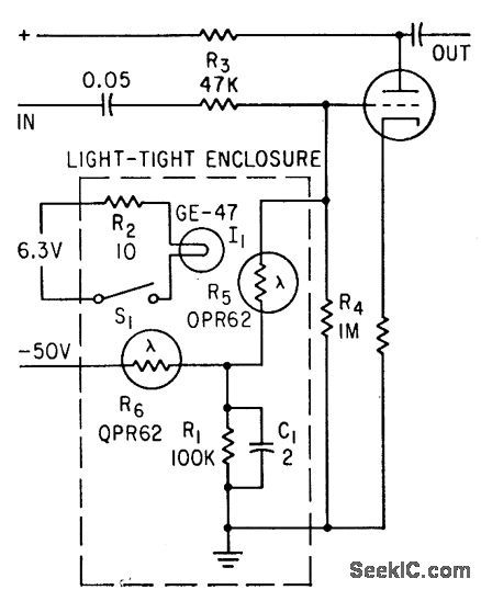
Photoresistors R5 and R6 isolate control function from signal circuit to avoid switching transients. S1 may be replaced by automatic pulsing circuit.-A. Martens, Noise-Free Keying Circuit, Electronics, 35:13, p 53. (View)
View full Circuit Diagram | Comments | Reading(1154)
MARK_SENSOR_FOR_CARDS
Published:2009/7/20 10:23:00 Author:Jessie
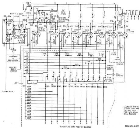
Automatically transcribes up to 40 pencil marks on specially printed 90-column cards into machine code and block-punches information into cards in any desired format at 150 cards per minute -F. A. Frankl, Transcribing Field Markings by Optical Scanning, Electronics, 34:31, p 49-51. (View)
View full Circuit Diagram | Comments | Reading(0)
DIODE_SENSOR_FOR_LASERS
Published:2009/7/8 23:25:00 Author:May
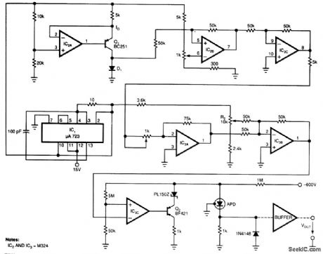


Laser-receiver circuits must bias their avalanche photo diodes (APD) to achieve optimal gain. Unfor-tunately, an APD's gain depends on the operating temperature. The circuit controls the operating voltage of an APD over a large temperature range to maintain the gain at the optimal value. The circuit uses D1 as a temperature sensor, thermally matched with the APD.A voltage regulator, IC1, supplies the necessary reference voltage to the circuit. IC2A and Q1 bias D1 at a constant current. IC2B, IC2C, IC3A/IC3B, and IC3C amplify D1's varying voltage and set Q2 to he optimal-gain corresponding value. Potentiometer RI controls the amplification over a range of 5 to 5. R2 controls the voltage level, which corresponds to the optimal gain of the APD at 22°C (the erature is specific to the type of APD). The circuit shown was tested with an RCA C 30954E APD. The tests cov-ered -40 to +70°C and used a semiconductor laser. The laser radiation was transmuted on the APD's active surface in the climatic room via fiberoptic cable. The gain varied by, at most, 10.2 dB over the entire temperature range. (View)
View full Circuit Diagram | Comments | Reading(1480)
ADJUSTABLE_DUTY_CYCLE_SQUARE_WAVE_OSCILLATOR
Published:2009/7/21 3:04:00 Author:Jessie
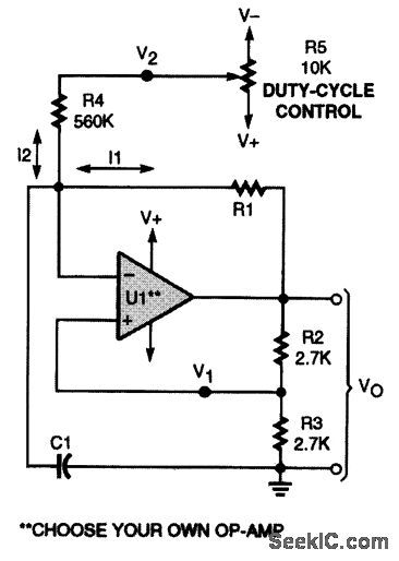
Use R5 to adjust this variable-duty-cycle square-wave generator. That potentiometer controls I2 to vary the timing. (View)
View full Circuit Diagram | Comments | Reading(1790)
AMBIENT_LIGHT_GNORING_OPTICAL_SENSOR
Published:2009/7/8 22:44:00 Author:May
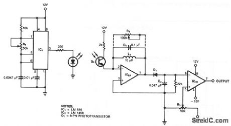
A resonance-tuned narrow-band amplifier reduces this optical object detector's sensitivity to stray light. C1 and L1 in IC2A's feedback loop cause the op amp to pass only those frequencies at or near the LED's 5-kHz modulation rate. IC2B's output increases when the received signal is sufficient to drop the negative voltage across C2 below the reference set by R2.
(View)
View full Circuit Diagram | Comments | Reading(1665)
CRYSTAL_OVEN_1
Published:2009/7/21 21:25:00 Author:Jessie
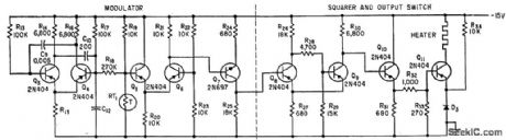
Thermistor RT1 senses temperature of crystal oscillator cavity and modifies output of asymmetric free running mvbr Q3-Q4 whose output is integrated by C12. Thermistor is followed by modulator, amplifier Q7, and four-transistor switch that applies power at fxed repetition frequency but with on time per cycle controlled by thermistor.-M. Lysobey, Microminiature Crystal Oscillator Using Wafer Modules, Electronics, 35:15, p 60-61.
(View)
View full Circuit Diagram | Comments | Reading(1148)
Portable_receiver
Published:2009/7/23 21:52:00 Author:Jessie
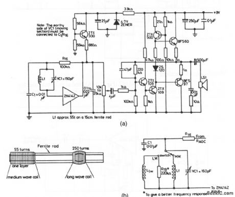
Figure 2-16A shows the ZN414Z (Fig. 2-14A) combined with extemal components to form a portable receiver (known as a Triffid receiver). Figure 2-16B shows the coil-winding details and waveband-selection circuits. (View)
View full Circuit Diagram | Comments | Reading(1307)
Fast_12_bit_A_D_converter
Published:2009/7/23 21:52:00 Author:Jessie
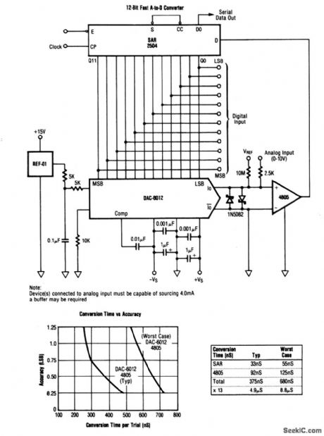
This circuit shows a DAC and comparator that is used with an SAR to form a 12-bit A/D converter. The analog input (0 to +10 V) is applied at the 4805 comparator noninverting input. Both parallel and serial digital outputs are available VREF can be trimmed for zero. Full-scale is trimmed by adjustment of the REF-01. (View)
View full Circuit Diagram | Comments | Reading(1570)
TRANSISTOR_SENSOR
Published:2009/7/8 4:48:00 Author:May
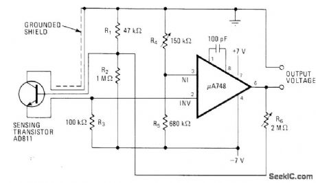
Use of bipolar supply for opamp makes electronic thermometer circuit fully linear even at low temperatures. Accuracy is within 0.05°C. Zero point is set by R4 and gain by R6—C .J .Koch,Diode or Transistor Makes Fully Linear Thermomete,Electronics,May 13,1976,p 110-112. (View)
View full Circuit Diagram | Comments | Reading(2452)
LOW_POWER_MAGNETIC_CURRENT_SENSOR
Published:2009/7/8 1:38:00 Author:May
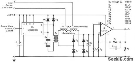
A transducer senses a direct current magnetically, providing isolation between the input and the output. The detecting-and-isolating element is a saturable reactor, in which the input current, to be measured, passes through a one-turn control coil. The transducer provides an output of 0 to 3 Vdc, an input current of 0 to 15 Adc, and consumes 22 mW at 10 Adc input.
Line driver U1 excites the saturable reactor L1 by feeding a 2.3-kHz square wave through transformer T1. The output of L1 is rectified by the bridge rectifier composed of diodes D3 through D6, then amplified by op amp U2, which has a gain of 20.
Diodes D1 and D2 commutate the reactive current fed back to the primary of T1 from L1. Without these diodes, large reactive voltage spikes on the primary would waste power and could destroy U1. Filter capacitor C1 stores the energy fed back through D1 and D2.
To minimize core losses, the core of T1 is made of an alloy of 80% nickel and 20% iron. To minimize capacitance, the primary and secondary windings are interleaved and progressively wound 350°. The primary and secondary windings consist of 408 and 660 turns, respectively, of #34 wire. (View)
View full Circuit Diagram | Comments | Reading(1255)
SILICON_DIODE_SENSOR
Published:2009/7/8 1:30:00 Author:May

Ordinary silicon diode having temperature coefficient of about -2 mV/℃over wide temperature range serves for sensing temperature differentials up to ±10°F with resolution of about 0.3°F. Two diodes connected in resistor bridge provide voltage proportional to temperature difference at terminals A and B.Pot suppliesvariable offset current corresponding to presettable temperature offset range. Low output voltage of bridge is amplified by opamp such as Motorola MC1741 which gives output swing of 30 V for input change of 0.3 mV. Buffer transistor is added for handling Ioad such as motor control relay.- Industrial Control Engineering Bulletin, Motorola, Phoenix, AZ, 1973, EB-4.
(View)
View full Circuit Diagram | Comments | Reading(1407)
ISOLATED_TEMPERATURE_SENSOR
Published:2009/7/7 23:44:00 Author:May

View full Circuit Diagram | Comments | Reading(2099)
O_63°C_TEMPERATURE_SENSOR
Published:2009/7/7 23:41:00 Author:May
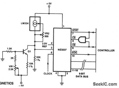
The temperature sensor provides an input to pm 3 of the NE5037 of 32 mV/°C。This 32 mV IS the value of one LSB for the NE5037. The LM334 is a three-terminal temperature sensor and provides a cur-rent of 1 μA for each degree Kelvin. The 32-KΩ resistor provides the 32 mV for each microamp through it, while the transistor bleeds off 273 μA of the temperature sensor (LM334) current. This bleeding lowers the reading by 273 K, thus converting from Kelvin to Celsius. To read temperature, conversion is started by sending a momentary low signal to pin 7 of the NE5037. When pin 10 of the NE5037 becomes low, conversion is complete and a low is applied to pin 9 of the NE5037 to read data on pins 11 and through 16. Note that this temperature data is in straight binary format. The controller can be a microprocessor in a temperature control application, or discrete circuitry in a simple temperature reporting application. (View)
View full Circuit Diagram | Comments | Reading(1667)
LOW_COST_HUMIDITY_SENSOR
Published:2009/7/7 7:59:00 Author:May
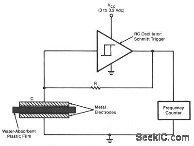
The sensor is an RC oscillator in which a water-absorbent plastic film is the insulator in the capacitive element. The capacitance of the film increases with the amount of water it absorbs from the air, and thus reduces the oscillation frequency. A frequency counter produces a digital output that represents the change in frequency and hence the change in relative humidity. The sensor can be used to measure humidity in the atmosphere, in the soil, and in industrial gases, for example. A Schmitt-trigger-type IC is con-nected to the capacitor, which consists of a film of a commercially produced sulfonated fluorocarbon polymer, 2 in. (5.08 cm) square, sandwiched between perforated metal plates. The oscillation frequency decreases almost linearly from about 100 to 16 kHz as the relative humidity increases from about 20 to 76%. (View)
View full Circuit Diagram | Comments | Reading(1255)
660_AND_1000_Hz_FOR_SSB_TESTING
Published:2009/7/21 22:06:00 Author:Jessie
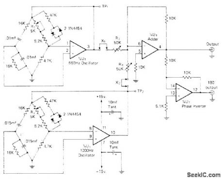
Produces two audio frequencies with all harmonics and cross products down 40 dB or more, as required for accurate testing of amateur SSB equipment. Two sections of Raytheon 4136D quad opamp serve as Wien-bridge audio oscillators, one at 1000 Hz and one at 660 Hz. Silicon signal diodes in each bridge act as nonlinear stabilization elements. Third section of opamp adds sine waves, and fourth section is simple inverter with gain of n for push-pull or balanced output. With all four pots at midvalue, adjust R2 for 12 V P-P at TP2 and adjust R4 for 12 V P-P at TP2. Open X2 and adjust R3 to give 12 V P-P from either output terminal to ground, then close X2 and repeat for X1 and R4. Output should now be 660 and 1000 Hz added linearly as required, with no cross-products. Use regulated ±15 V supply.-H. Olson, A One-Chip, Two Tone Generator, CQ, April 1974, p 48-49. (View)
View full Circuit Diagram | Comments | Reading(1212)
TILTMETER_INDICATES_SENSE_OF_SLOPE
Published:2009/7/7 3:24:00 Author:May
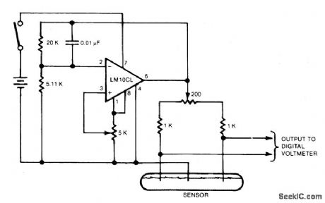
Electrodes are immersed in an electrolyte that remains level while the sensor follows the tilt of the body on which it is placed, more of one outer electrode and less of the other are immersed and their resistances fall or rise, respectively. The resistance change causes a change in the output voltage of the bridge circuit. The sensor forms the two lower legs of the bridge, and two 1000 ohm metal film resistors and a 200 ohm ceremet balance potentiometer form the two upper legs. In preparation for use, the bridge is balanced by adjusting the balance potentiometer so that the bridge output voltage is zero when the sensor is level. The bridge input voltage (dc excitation) is adjusted to provide about 10 millivolts output per degree of slope, the polarity indicating the sense of the slope. This scaling factor allows the multimeter to read directly in decrees if the user makes a mental shift of the meter decimal point. The scaling-factor calibration is done at several angles to determine the curve of output voltage versus angle. (View)
View full Circuit Diagram | Comments | Reading(1327)
_HI_LO_TEMPERATURE_SENSOR
Published:2009/7/7 2:45:00 Author:May
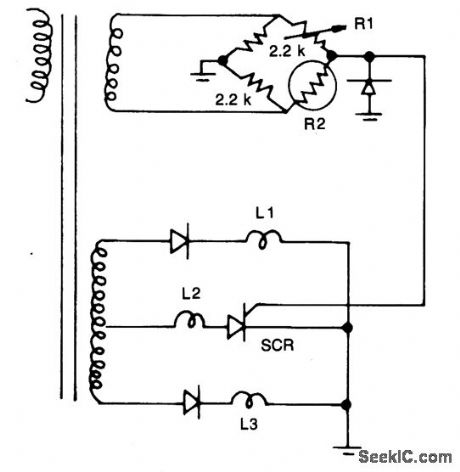
Resistors R1, R2, and the two 2.2 k resistors form a bridge circuit. R2 is a therrnistor, and RI sets the temperature at which L2 lights. Lower or higher temperatures light L1 or L3 to indicate an over- or under-temperature condition. (View)
View full Circuit Diagram | Comments | Reading(1033)
FIRE_SIREN
Published:2009/7/21 23:23:00 Author:Jessie
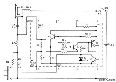
Pressing button produces rapidly rising wail, and releasing button gives slower lowering of frequency resembling sounds of typical siren on fire engine. Circuit uses National LM3909 IC operating from 1.5-V cell for driving 25-ohm loudspeaker, 1-μF capacitor and 200-ohm resistor determine width of loudspeaker pulse, while 2.7K resistor and 500-μF capacitor determine repetition rate of pulses.- Linear Applications, Vol. 2, National Semiconductor, Santa Clara, CA, 1976, AN-154, p 6-7. (View)
View full Circuit Diagram | Comments | Reading(1)
| Pages:11/27 1234567891011121314151617181920Under 20 |
Circuit Categories
power supply circuit
Amplifier Circuit
Basic Circuit
LED and Light Circuit
Sensor Circuit
Signal Processing
Electrical Equipment Circuit
Control Circuit
Remote Control Circuit
A/D-D/A Converter Circuit
Audio Circuit
Measuring and Test Circuit
Communication Circuit
Computer-Related Circuit
555 Circuit
Automotive Circuit
Repairing Circuit