
Sensor Circuit
Index 8
Voltage Waveform Circuit Of Welding Sensor Each Point
Published:2011/7/27 3:22:00 Author:Robert | Keyword: Welding Sensor, Point, Voltage, Waveform
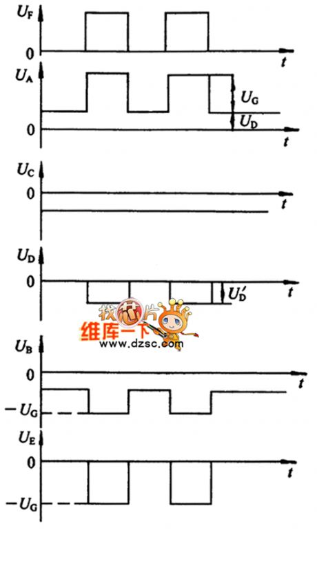
The picture shows the welding sensor each point's voltage waveform circuit. (View)
View full Circuit Diagram | Comments | Reading(1130)
OUT_OF_LIMIT_VOLTAGE_SENSOR
Published:2009/7/14 21:31:00 Author:May
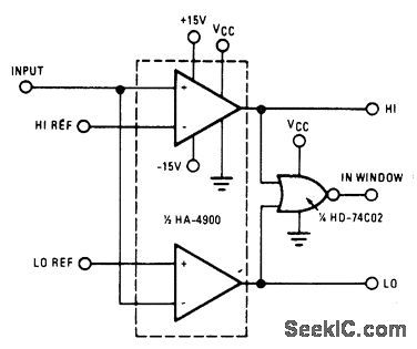
High switching speed, low offset current, and low offset voltage of Harris HA-4900/4905 precision quad comparator make circuit well suited for industrial process control applications requiring fast, accurate decision-making based on voltage levels. Outputs can be used to drive alarm indicator or initiate corrective action.- Linear & Data Acquisition Products, Harris Semiconductor, Melbourne, FL, Vol. 1, 1977, p 2-96. (View)
View full Circuit Diagram | Comments | Reading(1170)
WIND_DIRECTION_SENSOR
Published:2009/7/15 0:11:00 Author:Jessie
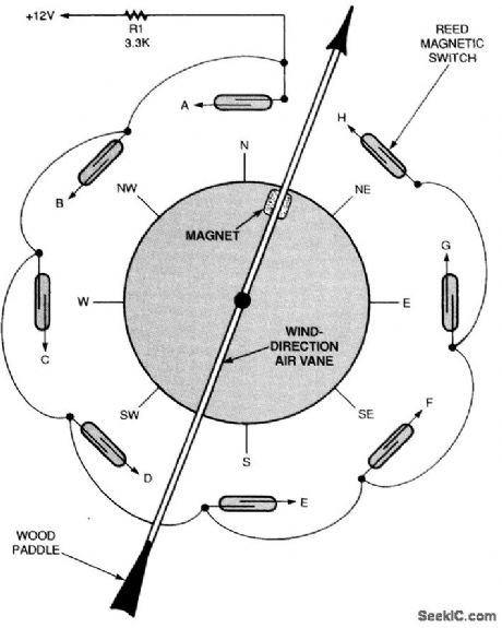
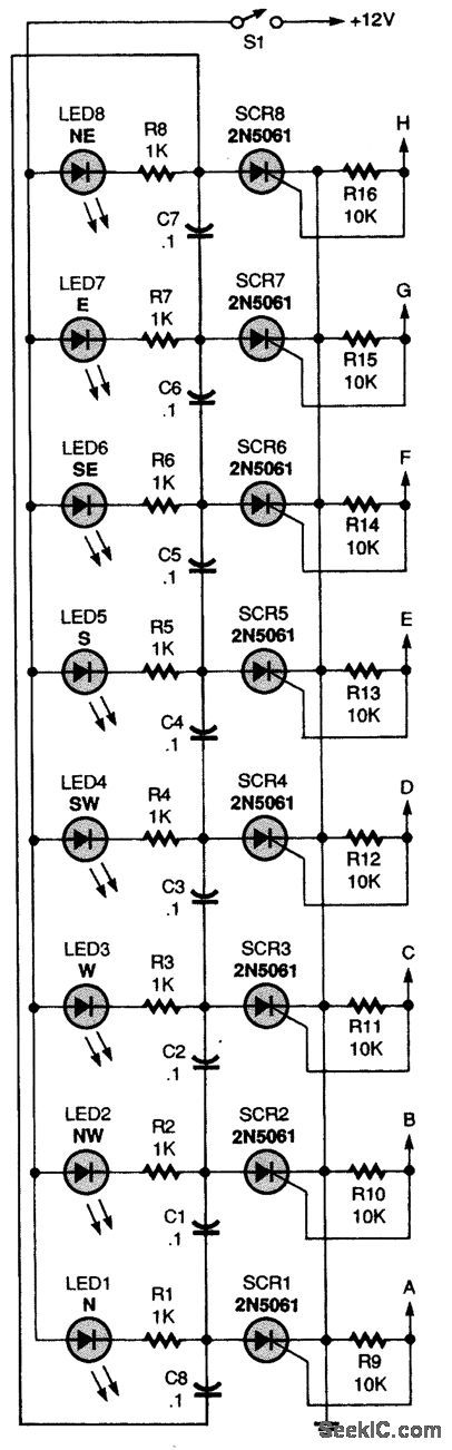
To use the circuit you will need a wind vane like the one shown. It should have a weighted front end and an air paddle in the rear. Attach a small, strong magnet to the front part of the wind-vane arm. Then, position eight reed magnetic switches in a circle around a piece of plastic pipe and electrically connect them (as shown). Note that the reed switches are electrically connected to points labeled A through H. Those points correspond to points A through H in the wind-direction decoder circuit. The decoder uses eight low-current 2N5061 SCRs and eight LEDs to latch and display the wind vane's position. If the wind vane is pointing due north, reed switch A is closed, sending current into the gate of SCR1. That current turns the thyristor on, causing it to light LED1. If the wind shifts slightly to a position in between north and northwest or north and northeast, without activating any of the reed switches, LED1 will remain on, indicating that the last wind direction was north. With SCR1 turned on, one end of capacitors C8 and C1 is pulled to ground. The other end of both capacitors is tied to the + 12-V bus through a resistor and LED; that means that both capacitors are charged to near 12 V. All other capacitors are not charged because both ends of each capacitor are returned to the +12-V bus through a resistor and LED. When the wind direction shifts to the northwest, reed switch B turns SCR2 on, thereby taking the positive end of C1, which is connected to its anode, to ground. This negative pulse turns SCR1 off as SCR2 turns on, lighting LED2 and turning off LED1. (View)
View full Circuit Diagram | Comments | Reading(9162)
CURRENT_SENSOR
Published:2009/7/14 23:45:00 Author:Jessie
Load current is sensed across base-emitter junction of output transistor. R1 controls OFF time and R2 controls ON time. Capacitor should be electrolytic rated above 16V.-M, Faulkner, Two Terminal Circuit Breaker, Wireless World, March 1977, p 41. (View)
View full Circuit Diagram | Comments | Reading(1441)
TOUCH_SENSOR
Published:2009/7/14 19:55:00 Author:May
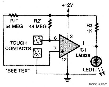
This circuit is a basic two-contact touch-switch sensor circuit. The negative input (pin 6) of IC1 is tied to the positive supply through R2 (which is actually two 22-MΩ resistors connected in series), while the positive input (pin 7) is connected through R1 (made up of two 22-MΩ and one 10-M.Ω resistor in series). (View)
View full Circuit Diagram | Comments | Reading(2138)
SEE_THROUGH_SENSOR
Published:2009/7/14 11:02:00 Author:May
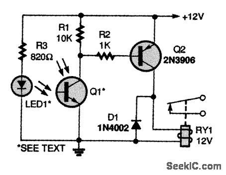
In this circuit, an infrared emitter LED (LED1) is aimed at an infrared phototransistor (Q1). As long as the IR light path between the two remains uninterrupted, transistor Q2 will keep relay RY1 closed. Any opaque object blocking the light path will cause RY1 to open. This circuit is a see-through-type light sensor. Such units are often used as part-in-place detectors and parts-counter sensors. (View)
View full Circuit Diagram | Comments | Reading(4459)
TOUCH_TON_E_ENCODER
Published:2009/7/14 6:14:00 Author:May
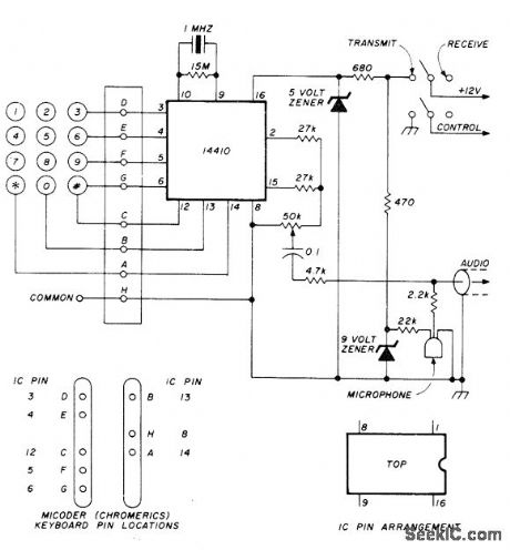
Crystal-controlled encoder using 14410 tone encoder operates from 12-V supply to provide good frequency stability along with correct balance between high and low tones. 50K level adjustment pot can be screwdriver type.-G. A. Wilson, The Micoder: Some Improvements, Ham Radio, Nov. 1978, p 42-43. (View)
View full Circuit Diagram | Comments | Reading(1194)
REFLECTIVE_SENSOR
Published:2009/7/15 22:49:00 Author:Jessie

The IR sensor circuit shown produces an output when LED1's light is reflected from an object back to phototransistor Q1. The LED and phototransistor should be mounted parallel to each other and aimed in the same direction. Without a reflective object, the voltage at the input of the LM339 comparator (IC1) is at or near ground level and the output at pin 1 of IC1 is high. When the phototransistor detects a reflected light signal, the voltage at Q1's emitter goes high, causing the comparator's output to go low. The 555 timer (IC2) is then triggered, and produces a timed output pulse at pin 3. The circuit's sensitivity is set by R4 and its output time period by R5. Note that in this circuit, all of the unused input and output pins of the LM339 must be tied to circuit ground. (View)
View full Circuit Diagram | Comments | Reading(8316)
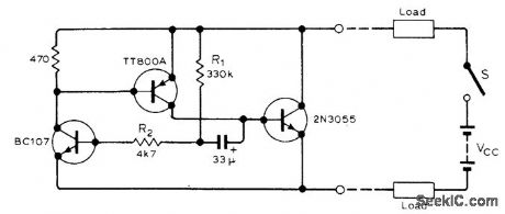
HYSTERESIS_STABILIZING_LIGHT_SENSOR
Published:2009/7/15 22:14:00 Author:Jessie
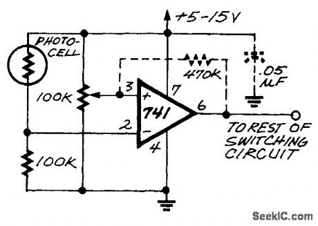
This light turn-on circuit originally had oscillation problems. The 470-kΩ resistor introduces the hysteresis to prevent the oscillation. You can experiment with the value of the resistor for best results in your application. (View)
View full Circuit Diagram | Comments | Reading(1319)
TIME_DELAYED_SCHMITT_AS_SENSOR
Published:2009/7/13 4:00:00 Author:May
Provides delay in sensor control until industrial process and system are started up and in normal operating mode. Delay is obtained with R-C network in additional transistor stage Q3.Photocell and R1 are interchangeable depending on polarity of control required from output.-L. T. Medveson, Time-Delayed Schmitt Sensor, EEE,14:7, p104. (View)
View full Circuit Diagram | Comments | Reading(1224)
SOS_BEACON
Published:2009/7/16 5:24:00 Author:Jessie
Gives 4 w output in 100-140 Mc or 220-260 Mc ranges. Uses class-C Hartley oscillator with crystal in feedback loop. Range is 100 miles for voice input and 200 miles for 1,000-cps tone of astable mvbr. - S. D. Czerwinski and F. S. Linn, Tiny Solid-State Transmitter May Save Your Life, Electronics, 35:48, p 90-91. (View)
View full Circuit Diagram | Comments | Reading(1580)
160_METER_PREAMP
Published:2009/7/16 5:01:00 Author:Jessie
Broadband 40-dB preamp has response range extending from broadcast band through VHF. Upper 3-dB point of amplifier is at 65 MHz. Heavy feedback stabilizes gain and provides 50-ohm characteristic.-D. DeMaw, Beat the Noise with a Scoop Loop, QST, July 1977, p 30-34.
(View)
View full Circuit Diagram | Comments | Reading(3234)
PULSE_HEIGHT_SENSOR_FEEDS_SCALER
Published:2009/7/16 22:39:00 Author:Jessie
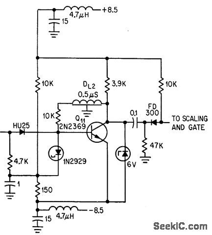
Tunnel-diode 1N2929 senses pulse height through isolating unijunction diode HU25.Voltage input signals above preset thresh-old give negative output pulse for scaler.-R. Cuikay and T. Callhan, Orbiting Observatory lo Measure Stars' Dim Light, Electronics, 37:9, p 28-31. (View)
View full Circuit Diagram | Comments | Reading(1199)
Zhonghua Car Air Bag System Circuit
Published:2011/7/18 4:57:00 Author:Felicity | Keyword: Zhonghua Car, Air Bag System, Circuit
View full Circuit Diagram | Comments | Reading(1014)
Zhonghua Car Air Conditioning System Circuit (the 3rd)
Published:2011/7/18 5:04:00 Author:Felicity | Keyword: Zhonghua Car, Air Conditioning System, Circuit
View full Circuit Diagram | Comments | Reading(943)
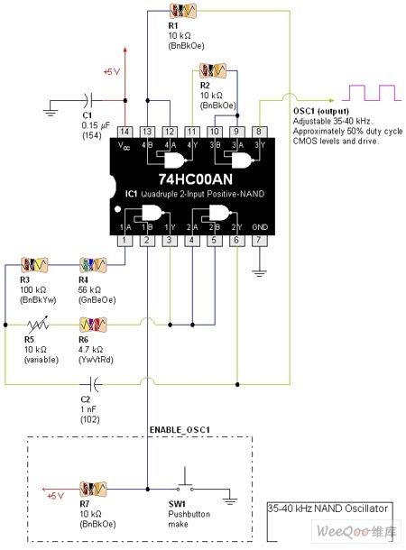
35KHz-40KHz Standard Square-wave Generator Circuit
Published:2011/7/18 5:14:00 Author:Felicity | Keyword: 35KHz-40KHz, Standard Square-wave Generator, Circuit
View full Circuit Diagram | Comments | Reading(1972)
SENSOR_KEYER
Published:2009/7/11 2:28:00 Author:May
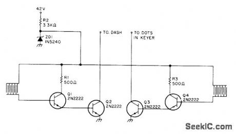
Skin resistance of about 10k creates dashes when finger touches grid pattern on left side of paddle and dots when other finger touches pattern on other side. Transistors act as solid-state switches. Developed for use with Heathkit CW keyer HD-10. Supply is 10V, obtained from 10-V zener connected through appropriate dropping resistor to higher-voltage source. Article covers construction of paddle by etching printed-wiring board.-T. Urbizu, Try a Sensor Keyer, 73 Magazine, Jan. 1978, p 184-185. (View)
View full Circuit Diagram | Comments | Reading(1422)
LM317_REGULATOR_SENSING
Published:2009/7/17 3:24:00 Author:Jessie
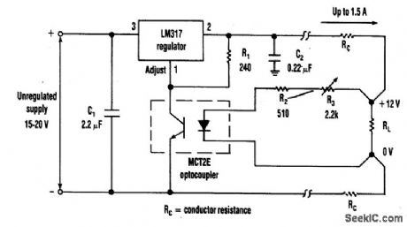
The optocoupler (as shown) provides load sensing for a 3-terminal regulator, such as the LM317 series. R1 sets a current of 5 mA through the optocoupler transistor and R3 is adjusted for 12 V across the load.
(View)
View full Circuit Diagram | Comments | Reading(3452)
HUM_DETECTING_TOUCH_SENSOR
Published:2009/7/11 1:22:00 Author:May
This touch sensor uses the 60-Hz hum pickup by the human body to drive a detector and relay drivers, Q1 and Q2. R5 controls sensitivity of the circuit. (View)
View full Circuit Diagram | Comments | Reading(1403)
RAIN_SENSOR
Published:2009/7/17 4:00:00 Author:Jessie
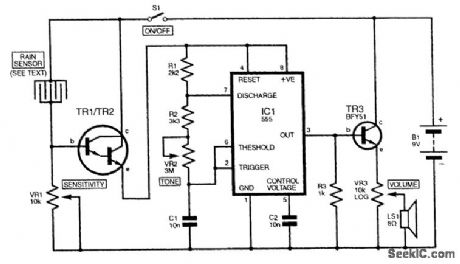
The figure shows a simple rain sensor design that incorporates pitch and volume controls in the alarm signal. Whenever the sensor is bridged by droplets of water, the Darlington transistor TR1/TR2 will conduct. This enables IC1, a 555 astable tone generator, to function, powering a small loud-speaker through a driver transistor (TR3). VR2 determines the pitch of the audio tone, which can be anything from about 25 Hz to 18 kHz, while VR3 adjusts the volume. The sensitivity of the circuit is set by VR1. The Darlington pair could be constructed with two separate ZTX300s or a single TlP122. For the sensor, use a small piece of stripboard, linking alternate strips into an interlocking design. The circuit will operate from a standard 9-V PP3-type battery. (View)
View full Circuit Diagram | Comments | Reading(4095)
| Pages:8/27 1234567891011121314151617181920Under 20 |
Circuit Categories
power supply circuit
Amplifier Circuit
Basic Circuit
LED and Light Circuit
Sensor Circuit
Signal Processing
Electrical Equipment Circuit
Control Circuit
Remote Control Circuit
A/D-D/A Converter Circuit
Audio Circuit
Measuring and Test Circuit
Communication Circuit
Computer-Related Circuit
555 Circuit
Automotive Circuit
Repairing Circuit