
Sensor Circuit
Index 24
Reed switch current sensor circuit diagram
Published:2011/5/9 21:44:00 Author:Nicole | Keyword: reed switch, current, sensor
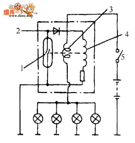
As shown in the figure, it is a current sensor circuit, when the switch closes, if all the bukbs work normally, it has rated current in current coil, then under the action of magnetic force which is produced by coil, the reed switch closes, if the bulb wire is breaking, the related current reduces, the magnetic force drops off, it makes reed switch cut off, then it will alarm.
(View)
View full Circuit Diagram | Comments | Reading(3300)
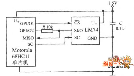
68HC11 single chip microcomputer circuit diagram composed of intelligent temperature sensor
Published:2011/5/10 3:25:00 Author:Nicole | Keyword: single chip microcomputer, intelligent temperature sensor
View full Circuit Diagram | Comments | Reading(1952)
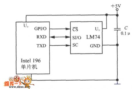
196 single chip microcomputer circuit diagram composed of intelligent temperature sensor
Published:2011/5/10 2:46:00 Author:Nicole | Keyword: single chip microcomputer, intelligent temperature sensor
View full Circuit Diagram | Comments | Reading(627)
Laser sensor indication circuit diagram
Published:2011/5/10 3:45:00 Author:Nicole | Keyword: Laser sensor
View full Circuit Diagram | Comments | Reading(904)
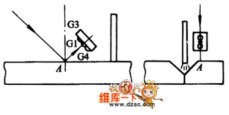
Welding sensor transverse tracking basic circuit diagram
Published:2011/5/10 3:43:00 Author:Nicole | Keyword: Welding sensor, transverse tracking
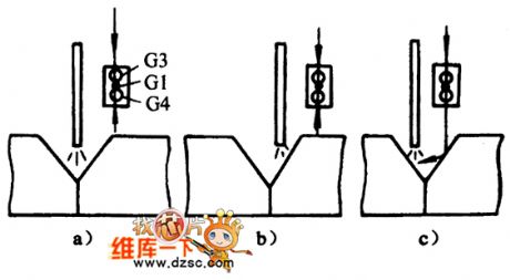
a)appropriateness b)right skewed c)left skewed (View)
View full Circuit Diagram | Comments | Reading(766)
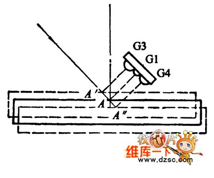
Welding sensor high and low tracking basic circuit diagram
Published:2011/5/10 3:31:00 Author:Nicole | Keyword: Welding sensor, high, low, tracking
View full Circuit Diagram | Comments | Reading(754)
Permeating Optical Interrupter Structure And Circuit
Published:2011/5/9 3:19:00 Author:Sharon | Keyword: Permeating, Optical Interrupter, Structure
The figure shows the two permeating interrupter structures.Their light-emitting and optical components are separated by a certain interval, and the middle is groove for objects to get through.When the element objects get through, the radiation from light emitting device shines on the optical devices directly, and the optical signal is output as electrical signal. When there are objects inside the interrupter, the radiation of light emitting devices will be blocked, then there is no light from the optical devices, and there is no output signal accordingly.This will identify whether or not there is object in it.Permeating optical interrupter is mainly used for optical control and optical measurement circuits, and can also be used to detect the existence of objects, direction of their movement and speed measurement . (View)
View full Circuit Diagram | Comments | Reading(1595)
MN1220 Memory Integrated Circuit
Published:2011/5/8 21:59:00 Author:Sharon | Keyword: Memory, integrated
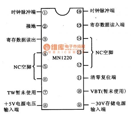
MN1220 is memory integrated circuit produced by Matsushita, widely used in televisions, audio equipment, DVD players and so on. 1. FeaturesMN1220 IC is mainly composed of the memory matrix within the circuit, reset circuit and data input / output interface circuit. 2. Pin functions and dataMN1220 IC is in 16-pin dual in-line package. The pin functions are shown in the figure, and the operating parameters are listed in Table. (View)
View full Circuit Diagram | Comments | Reading(1955)
Object Motion Direction Identification Circuit
Published:2011/5/9 2:42:00 Author:Sharon | Keyword: Object Motion, Direction Identification
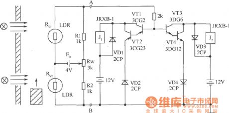
Place two objects of similar resistance and performance on the same side of the object motion path, with an appropriate distance from each other. The relative position of the other side is installed two light sources respectively, so that objects between the light source and photosensitive resistancemove move in direct line. The circuit in the figure can judge the direction of the moving objects. The circuit is formed by two parts: bridge and the polarity discrimination. Rs1, Rs2, R1, R2 and Rw form the bridge, E0 provides power supply and A, B-side output. Before measuring, make Rs1 and Rs2 in the same shade or light, adjust Rw, so that the bridge is balanced. UAB = 0V. When measuring, when the object move from the bottom to up, Rs2 is the first to be shaded, resistance increases, Rs1 is in light, resistance is less, and bridge is unbalanced. UA> UB, UAB> 0V, the VT1, VT2 is ended, VT3, VT4 get through, relay J1maintains the off state, and J2 pulls. When the object continues to move upward to the Rl position, the opposite, J1 pulls, J2 opens. If the object conducts the top-down movement, contrary to the above, J1 is prior J2 to pull. Thus, J1 and J2's pull sequences can determine direction of objects movement, and provide the corresponding switching control signal output. (View)
View full Circuit Diagram | Comments | Reading(956)
Beam Blocking Alarm Circuit
Published:2011/5/9 2:59:00 Author:Sharon | Keyword: Beam Blocking, Alarm
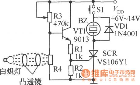
As shown in the figure, when the photosensitive resistor R4 is irradiated, the resistance is low, thus, transistor VT1 and one-way thyristor SCR are closed; when the beam is blocked, the base voltage of VT1 increase, VT1, SCR is conducted, and audible alarm buzzer BZ is energized. S1 is the reset switch. Press S1, the circuit stops the alarm. (View)
View full Circuit Diagram | Comments | Reading(988)
A Precision bright light control circuit
Published:2011/5/9 3:07:00 Author:Sharon | Keyword: Precision, bright, light control
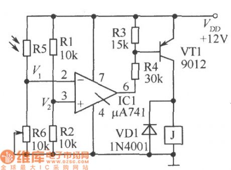
The circuit shown is a precision bright light control circuit. Its work will not be affected by power supply voltage and ambient temperature. Resistors R1, R2, R6 and the photosensitive resistor R5 constitute the two bridge arms of Wheatstone bridge. (View)
View full Circuit Diagram | Comments | Reading(768)
Precision Dimming Light Control Circuit
Published:2011/5/9 3:18:00 Author:Sharon | Keyword: Precision, Dimming Light Control
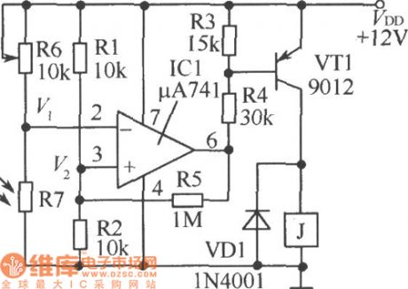
Precision dimming light control circuit is as shown in the figure. Since the introduction of R5 has brought a small amount of positive feedback, with the change of the light, circuit action will be slightly delayed in order to avoid the relay's frequent jitter at the time ofthe light intensity is in critical state.
(View)
View full Circuit Diagram | Comments | Reading(1034)
Time-setting and time-saving switch circuit
Published:2011/5/9 3:38:00 Author:Sharon | Keyword: Time-setting, time-saving, switch
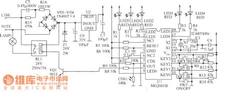
Nowadays, the door and light are mostly controlled by manual switches. Frequent forgetting to turn on or off the lights result in inconvenience and energy waste. If we can increase the light control and timing functions of them, automation and energy-saving effect can be achieved. Ready-made light control timer ICMG2001B is suggested here. It is a cheap 1h ~ 36h9 block optional timing and delay IC. The external circuit is simple with a light-driven port, photoresistors interface, low-cost 32.768kHz crystal as clock source, and the time accuracy is up to one hundred thousandth and it's very suitable for making lamps automatic control circuit. According to actual situation, choose the basic 4 block time (1h, 3h, 5h, 8h) plus one switching function to form a 5-speed light control timer circuit, and then install them into the normal 5-speed surface shell to make a 5 block light control timer switch so as to control the door lights or street lamps. Circuit is as shown in the figure.
(View)
View full Circuit Diagram | Comments | Reading(936)
Colorimeter and Concentration Meter Circuit
Published:2011/5/9 2:12:00 Author:Sharon | Keyword: Colorimeter, Concentration Meter
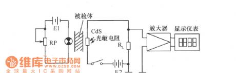
As the circuit shows, when the sample is inserted, the photosensitive resistor will transform its received light intensity into electrical signals according to the concentration or density of sample size, and drive display instrument through the amplifier. The measuring instrument is generally used for the concentration of emulsion, gray film density and transmittance measurements. Amplifier and display instruments can be selected according to specific needs. RP regulation can be detected by different samples.
(View)
View full Circuit Diagram | Comments | Reading(1403)
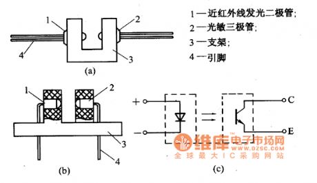
Photodiode and Switch Combined Optocoupler Appearance and Circuit
Published:2011/5/9 1:33:00 Author:Sharon | Keyword: Photodiode, Switch, combined optocoupler, appearance
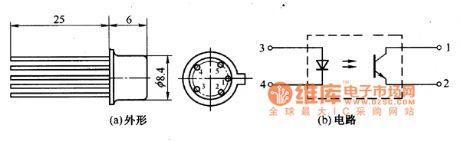
Photodiode and Switch Combined Optocoupler The optocoupler is a combination of light-emitting diodes, silicon photodiode and 3DK switch transistor. Its appearance is as shown in the figure and the main parameters are listed in the Table. (View)
View full Circuit Diagram | Comments | Reading(783)
Phototransistor Optical Optocoupler Appearance and Circuit
Published:2011/5/9 1:41:00 Author:Sharon | Keyword: Phototransistor, Optical Optocoupler, Appearance
Phototransistor Optical Optocoupler Appearance and Circuit is as shown in the figure. (View)
View full Circuit Diagram | Comments | Reading(900)
Servo Control Integrated Circuit
Published:2011/5/6 2:06:00 Author:Sharon | Keyword: Servo Control, Integrated
MN67641VDGF IC pin functions and data
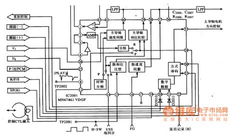
MN67461VDGF IC's internal circuit block diagram and its typical application circuit.
MN67461VDGF is servo control IC produced by Panasonic company, widely used in the video camera, like the Panasonic NV-M8000 camera.1. Features. MN67461VDGF IC's internal structure is mainly made by drum phase servo, drum speed servo, capstan phase servo, working method decoder, and digital tracking circuit and other associated circuit.
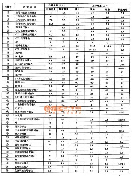
2. Pin functions and data. MN67461VDGF IC is sealed in 44-pin plastic, its pin functions and data listed in Table.
3. Typical Application Circuit. MN67461VDGF IC's internal circuit block diagram and its typical application circuit as shown in the table. (View)
View full Circuit Diagram | Comments | Reading(3127)
MN12C2010 Memory Integrated Circuit
Published:2011/5/8 22:16:00 Author:Sharon | Keyword: Memory, Integrated
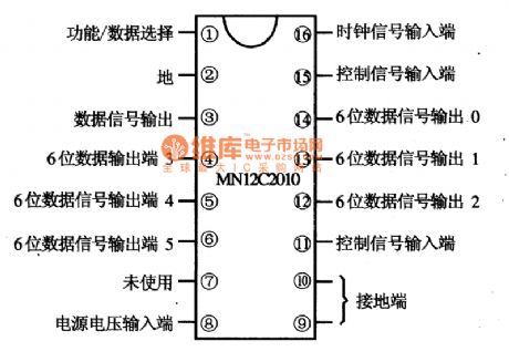
MN12C2O10 is memory integrated circuit produced by Matsushita, widely used in televisions, audio equipment, air conditioners and other series of control circuit. 1. FeaturesMN12C2010 IC embedded data storage matrix circuit, clock circuit and control circuit. 2. Pin functions and data MN10C2010 IC is in 16-pin double row package. The pin functions is shown in the figure, and the operating parameters are listed in Table.
(View)
View full Circuit Diagram | Comments | Reading(1368)
MN12C2O1D Memory Integrated Circuit
Published:2011/5/8 22:27:00 Author:Sharon | Keyword: Memory, Integrated
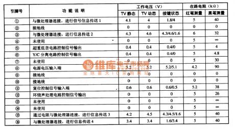
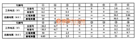
MN12C2O1D is memory integrated circuit produced by Matsushita. It usually forms large screen color TV's remote control system with MN15287KWEC31 Micro-chip integrated circuits, controlling the various functions of color TV.
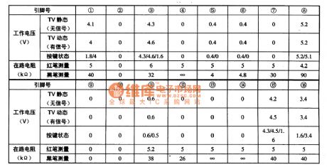
MN12C201D IC is in 16-pin plastic dual in-line structure. The pin functions and data are listed in Table, and the data is measured in Konka (TA8611 + TA8759) movement of color television. (View)
View full Circuit Diagram | Comments | Reading(1232)
Magnetic disc moving direction discrimination circuit diagram composed of magnetosensitive resistance
Published:2011/5/9 2:24:00 Author:Nicole | Keyword: magnetic disc, moving direction, discrimination, magnetosensitive resistance

The figure1 is a magnetic disc moving direction discrimination circuit which is composed of magnetosensitive resistance. In the circuit, R(M1) and R(M2) are magnetosensitive resistances, in order to improve the temperature characteristic of magnetosensitive resistance, it should adopt series connection. When the magnetic disc A moves, VT1 turns on, the collector outputs pulse singal which is shown in the figure1(c). If the magnetic disc continues to move, it keeps away from R(M1) and approaches R(M2), then VT1 turns off, VT2 turns on. According to the change of magnetic field, VT1 and VT2 output pulse singal which is shown in the figure1(c). So, it can judge the magnetic disc's direction of movement according to the sequence of pulse singal.
(View)
View full Circuit Diagram | Comments | Reading(1149)
| Pages:24/27 At 2021222324252627 |
Circuit Categories
power supply circuit
Amplifier Circuit
Basic Circuit
LED and Light Circuit
Sensor Circuit
Signal Processing
Electrical Equipment Circuit
Control Circuit
Remote Control Circuit
A/D-D/A Converter Circuit
Audio Circuit
Measuring and Test Circuit
Communication Circuit
Computer-Related Circuit
555 Circuit
Automotive Circuit
Repairing Circuit