
Signal Processing
Index 174
Integral circuit principle diagram
Published:2011/5/26 8:14:00 Author:Christina | Keyword: Integral, principle
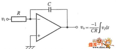
The Integral circuit principle diagram is as shown:
(View)
View full Circuit Diagram | Comments | Reading(820)
Sharp 29NF-1 protection circuit
Published:2011/5/26 2:52:00 Author:Christina | Keyword: Sharp, protection

The Sharp 29NF-1 protection circuit is as shown:
(View)
View full Circuit Diagram | Comments | Reading(538)
The power supply circuit of 555 multi-function fridges (1)
Published:2011/5/30 22:36:00 Author:Borg | Keyword: power supply circuit, multi-function fridges
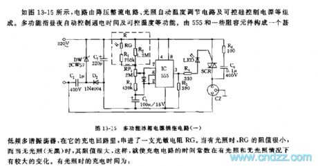
See as Figure 13-15, the circuit consists of the step-down rectifier circuit, lighting auto temperature adjusting circuit and controllable silicon control circuit, etc. The multi-function here means auto control of conducting time day and night, and controllable temperature, etc. 555 and some RC-components form a very low multi-resonate oscillator, in the oscillator circuit, a LDR is series connected. When there is light, the resistance of RG is very small; and when it dark outside, the resistance is very large, therefore, the time constant of the charging circuit changes a lot in the bright and dark environments. (View)
View full Circuit Diagram | Comments | Reading(559)
The power supply outlet circuit of 555 multi-function fridges (2)
Published:2011/5/30 22:58:00 Author:Borg | Keyword: power supply outlet, multi-function fridge
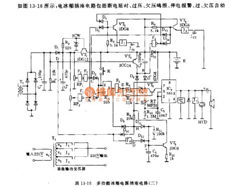
See as Figure 13-16, the fridge outlet includes sub-circuits of power-off time delay, over/low voltage warning,over/low voltage adjusting and temperature indication, etc. when mains voltage is higher than 245v or lower than 180v, the output voltage will be adjusted to about 220V; when the power is off, it will buzz.
RP1,RP2,F1,F2,F3 and so on consist a over/low/off power detection circuit, IC1 is connected as a Schmidt trigger. When it's over/low/off power, the output terminal of IC1 will be in a low LEV, VT5 is conducting, which makes the oscillator, consisting of IC2,R10,RT and C5, work.
(View)
View full Circuit Diagram | Comments | Reading(634)
The 555 timer circuit of independent adjustable on/off timing
Published:2011/5/30 20:52:00 Author:Borg | Keyword: timer circuit, adjustable
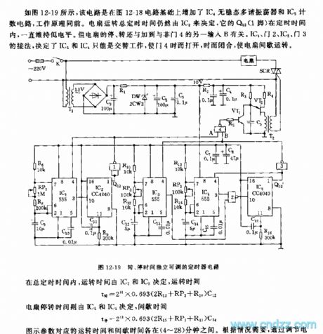
See as Figure 12-19, the circuit is added with a IC4 non-steady multi-resonate oscillator and IC5 counting circuit on the base of Figure 12-18, but the working principles are the same. The general timing of fan running is still decided by IC2 whose Q12 point (1-pin) remains in a low LEV during the time, but the switch of ON/OFF has something to do with another input B of NAND 4. The connection method of IC4, NAND 2, IC5 and NAND 3 decides that IC3 and IC4 can only work in turn, which makes the NAND 4 open and close now and than, and the fan runs intermittently.
(View)
View full Circuit Diagram | Comments | Reading(1141)
The 555 controller circuit of auto-switch wind speed of 10 degrees
Published:2011/5/30 3:11:00 Author:Borg | Keyword: controller circuit, wind speed
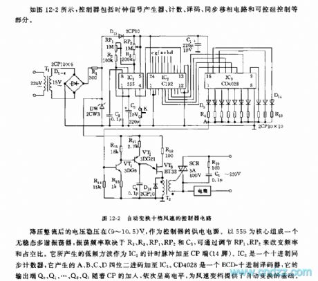
See as Figure 12-2, the controller includes clock signal generator, counting, decoding and synchronous moving-phase circuit, and controllable silicon controller,etc. The voltage, after being stepped down and rectified, keeps between 9 to 10.5V, and it is the power supply of the controller. A non-steady multi-resonate oscillator is formed based on the 555, the frequency depends on R2,R3,RP1,RP2 and C3, and the frequency and duty cycle can be changed by adjusting RP1 and RP2. The low-frequency square wave generated by the circuit is used as the timing pulse, and the pulse is imposed on the CP terminal(14-pin). (View)
View full Circuit Diagram | Comments | Reading(639)
The auto detecting and heating circuit of 555 minimum temperature
Published:2011/5/29 20:53:00 Author:Borg | Keyword: detecting and heating circuit, minimum temperature
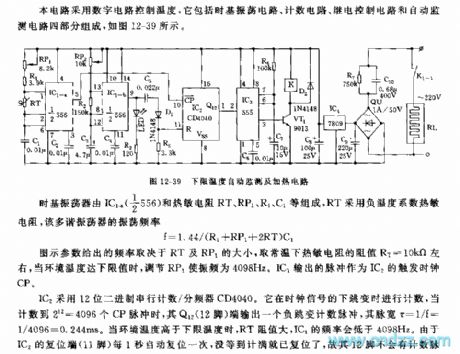
The circuit controls temperature in a digital way, which includes four sub-circuits, they are time-base oscillation circuit, counting circuit, relay control circuit and auto monitoring circuit, see as Figure 12-39.
Figure 12-39 The auto detecting and heating circuit of the minimum temperature The time-based oscillator consists of IC1-4(1/2*556) and thermistor of RT1,RP1,R1 and C1,etc, RT is made of negative temperature coefficient thermistors, and the frequency of the multi-resonate oscillator is:
f=1.44/(R1+RP1+2RT)C1
The frequency of the parameter in the figure depends on RT and RP1,and the selected resistance of the thermistor is about RT=10KΩ. (View)
View full Circuit Diagram | Comments | Reading(541)
The 555 sound warning thermometer circuit of 40℃ limited temperature
Published:2011/5/30 21:13:00 Author:Borg | Keyword: sound warning thermometer, limited temperature
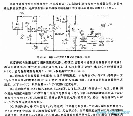
Apart from indicating the environment temperature, the thermometer can launch acousto-optical warning signals when it is higher than 40℃ outside. This circuit includes the temperature sensing head, voltage comparator, trigger, stereo circuit and meter indication circuit, etc, see as Figure 12-40. The temperature sensing head is made of the LM35DZ integrated circuit, which can output corresponding DC current in proportion in accordance with the changing temperature outside, the linearity is good, when the temperature changes 1℃, the current changes 10mV, and the precision is 0.5℃ when it is 25℃ outside. (View)
View full Circuit Diagram | Comments | Reading(533)
The temperature controller circuit of the 555 breeze ceiling fan
Published:2011/5/27 21:24:00 Author:Borg | Keyword: temperature controller, breeze ceiling fan
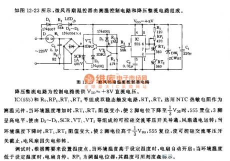
IC(555),R5,RP1,RT1,RT2 and so on form a dual steady state trigger circuit, RT1 and RT2 is fixed with NTC thermistor as the temperature detection device, when the environment temperature is rising, the resistances of RT1 and RT2 are getting down, and the 2-pin is in a 1/3 VDD LEV, 555 is offset, 3-pin is in a high LEV, then the controllable silicon AC zero-voltage switch which consists of D2~D5,SCR,VT1 and VT2 is conducting, the fan runs; when the environment temperature is getting down, the resistances of RT1 and RT2 is rising, and the LEV of 2-lead is higher than 1/3VDD, 555 is offset, then the controllable silicon AC zero-voltage switch is cut off and the fan stops due to lack of power. (View)
View full Circuit Diagram | Comments | Reading(870)
The 555 breeze ceiling fan timer circuit
Published:2011/5/28 20:14:00 Author:Borg | Keyword: ceiling fan, timer circuit
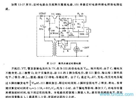
See as Figure 12-27, the timing circuit consists of step-down rectifier circuit, 555 single steady timing circuit and relay control circuit.
Figure 12-27 the breeze ceiling fan timer circuitAfter the fan has started, the voltage on injection pole of VT1 pipe is about 7v, which is the power supply voltage of 555. And when it is starting, since the voltage on C2 can not be changed suddenly, and the diode of D2 is in a reverse bias state, so the 2-pin of 555 is in a low LEV which makes 555 offset, the 3-pin is in a high LEV, J pulls in and J1-1 is getting through, the outlet of CZ gets power and the fan runs. (View)
View full Circuit Diagram | Comments | Reading(593)
The auto-control circuit of 555 ventilators
Published:2011/5/27 20:46:00 Author:Borg | Keyword: auto-control circuit, 555 ventilators
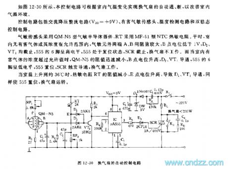
See as Figure 12-30, the control circuit can fulfill the auto on/off of the ventilator, so that the interior air temperature can be improved. The control circuit includes the AC step-down rectifier circuit(), harmful gas sensor, temperature test circuit and dual steady control circuit. The air sensor is made of QM-N5 gas-sensitive elements, and RT is fixed with the MF-51 NTC thermistor. Usually, when the harmful gas or it content is in the permissible range, the resistance between the two terminals A and B of the gas-sensitive sensor is high, and the LEV of B terminal is lower than 1V.
(View)
View full Circuit Diagram | Comments | Reading(530)
The speed regulation switch circuit of 555 infrared controlled fans
Published:2011/5/29 21:55:00 Author:Borg | Keyword: speed regulation switch, infrared controlled fans
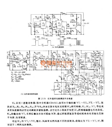
See as Figure 12-24, the speed regulation switch consists of infrared generator, receiver and decoder, etc. It is encoded by infrared pulse, in the distance of 5~5m, the encoder and decoder can do their job reliably, the switch can fulfill the control and switch of five kinds of wind speed(continuous wind), 3-level gusts and breezes. In Figure (a), there is a infrared generator. IC1,D1,R2,R1 and C2 consist a low-frequency multi-resonate oscillator, whose oscillating period is T=t(charging)+t(discharging), of which t(charging)=0.693R2C2, the parameter in the figure is 400μs; t(discharging)=0.693R1C1, the parameter in the figure is 15ms. (View)
View full Circuit Diagram | Comments | Reading(596)
The infrared remote control circuit of 555 domestic fans
Published:2011/5/30 21:57:00 Author:Borg | Keyword: remote control, domestic fans
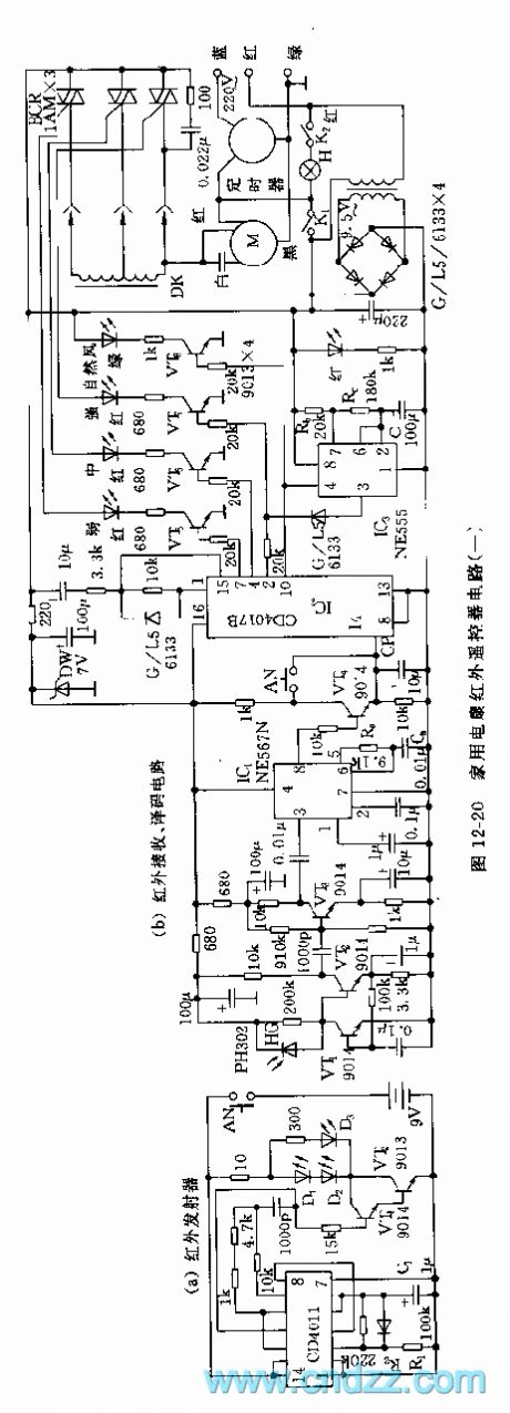
See as Figure 12-20, the remote control is use to the Changcheng FS-19-40 infrared remote control floor fan, and the fan is a recently upgraded product of Shuzhou fan factory. The remote control circuit includes an infrared emitter and an infrared decoding receiver controller.The emitting circuit consist 4 CD4011 2-terminal NANDs, VT1 and VT2 drive circuits and infrared LED, etc. Two CD4011 NANDs, R1,R2 and C1 consist the pulse oscillator, and the pulse drives VT1 and VT2 amplifiers after it is rectified, then D1,D2 and D3 emit infrared pulses.
(View)
View full Circuit Diagram | Comments | Reading(588)
The 555 wind speed controller circuit
Published:2011/5/27 21:51:00 Author:Borg | Keyword: wind speed controller
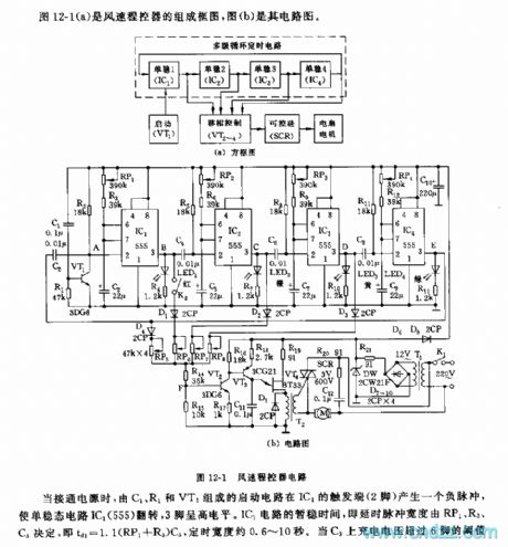
Figure 12-1(a) is a combination circuit of wind speed controller, and (b) is a another circuitWhen the power is getting through, the starting circuit consisting of C1, R1 and VT1 generates a negative pulse on the trigger terminal(2-lead) of IC1, which reverses the single steady circuit of IC1(555), and the 3-lead is in a high LEV. The temporarily steady time of IC1, i.e the pulse width of time delay, is decided by RP1,R2 and C3, i.e td=1.1(RP1+R3)C3, the timing width is about 0.6~10s. When the charging voltage on C3 is higher than the 6-pin threshold value LEV of 2/3VDD, the trigger is reset, and 3-pin is in a low LEV. (View)
View full Circuit Diagram | Comments | Reading(868)
The 555 inducing auto-ventilation controller circuit
Published:2011/5/29 20:02:00 Author:Borg | Keyword: auto-ventilation controller
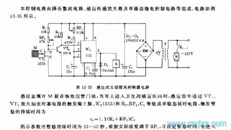
The control circuit consists of sub-circuits of step-down rectifier, sensing amplifier and single steady relay control, etc. The circuit is as shown in Figure 12-35.
Figure 12-35 The inducing auto-ventilation controller circuitThe sheet metal,M, is linkdd to the door of the field FET, when someone comes in the sensing area of washing rooms, the sensing signals are delivered to the trigger terminal(2-pin) of the time-based circuit after they are amplified by VT1 and VT2. (View)
View full Circuit Diagram | Comments | Reading(632)
The simulating natural wind controller circuit
Published:2011/5/28 20:31:00 Author:Borg | Keyword: natural wind
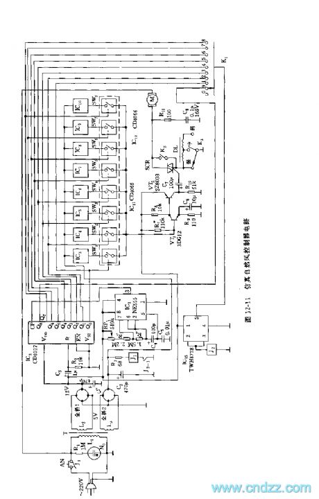
See as Figure 12-11, the circuit consists of rectifier power supply, clock signal source, counting distributor, random signal source, analog e-switch, timely alternating switch and controllable silicon control circuit, etc. 555,RP1,R5,R6,C4 and so on consist a non-steady multi-oscillator, once the power is on, the oscillator is shaking. The period is T=0.693(RP1+R5+2R6)C4, and the parameter period in the figure is about 5min.IC2(CD4017) is a decimal counter/pulse distributor. The output of IC1 is as the counting clock of IC2, which is imposed in CP terminal(14-pin).
(View)
View full Circuit Diagram | Comments | Reading(624)
The 555 analog natural wind circuit(1)
Published:2011/5/30 21:26:00 Author:Borg | Keyword: natural wind
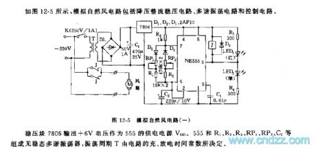
See as Figure 12-5, the analog natural circuit includes a step-down rectifier circuit, multi-resonate oscillating circuit and control circuit.
The oscillating period and the duty cycle of the pulse square wave can be changed by adjusting RP1 and RP2. As D1 and D2 are linked in the charging and discharging circuits respectively, the charging time and discharging time can be adjusted separately. At the beginning of power-on, since the voltage on C2 can not mutate, the 2-pin of 555 is like a grounded connection LEV, and 3-pin is in a high LEV, the relay is still, the normally closed contact makes the fan get power,rotate and launch winds.
(View)
View full Circuit Diagram | Comments | Reading(549)
The 555 analog natural wind circuit(3)
Published:2011/5/30 21:38:00 Author:Borg | Keyword: natural wind
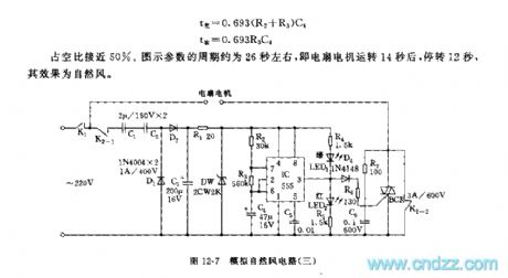
See as Figure 12-7, the circuit includes a capacitor step-down rectifier circuit, 555 multi-resonate oscillator and controllable silicon control circuit.The rectifier circuit generates a LEV of +7V as the power supply of 555. IC, R2,R3 and C4 consist a non-steady multi-resonate oscillator, whose frequency is T=0.693(R2+2R3)C4, of whichT(light)=0.693(R2+R3)C4T(discharging)=0.693R3C4The duty cycle is close to 50%. The period of the figure parameter is about 26S, i.e after the fan motor runs for about 14s, it stops and keeps still for 12s, the effect is the natural wind.
Figure 12-7 the analog natural wind circuit(3) (View)
View full Circuit Diagram | Comments | Reading(639)
M17 movement protection circuit
Published:2011/5/30 1:52:00 Author:Christina | Keyword: movement, protection
The M17 movement protection circuit is as shown:
(View)
View full Circuit Diagram | Comments | Reading(542)
Angell water dispenser circuit
Published:2011/5/30 2:26:00 Author:Christina | Keyword: Angell, water dispenser
The Angell water dispenser circuit is as shown:
(View)
View full Circuit Diagram | Comments | Reading(2107)
| Pages:174/195 At 20161162163164165166167168169170171172173174175176177178179180Under 20 |
Circuit Categories
power supply circuit
Amplifier Circuit
Basic Circuit
LED and Light Circuit
Sensor Circuit
Signal Processing
Electrical Equipment Circuit
Control Circuit
Remote Control Circuit
A/D-D/A Converter Circuit
Audio Circuit
Measuring and Test Circuit
Communication Circuit
Computer-Related Circuit
555 Circuit
Automotive Circuit
Repairing Circuit