
Signal Processing
Index 177
555 DGK—63L double functions disinfection cabinet circuit
Published:2011/5/25 4:06:00 Author:TaoXi | Keyword: 555, double functions, disinfection cabinet
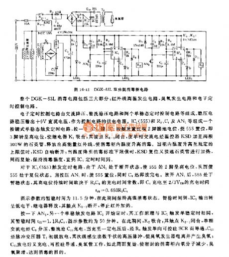
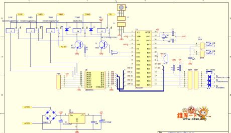
The DGK—63L double functions disinfection cabinet circuit is composed of three parts: the infrared ray high temperature generating circuit, the ozone generating circuit and the electronic timing control circuit.
The electronic timing control circuit is composed of the AC step-down circuit, the rectifier voltage stabilization circuit and two monostable timing control circuits. The voltage stabilization circuit outputs the +9V DC voltage as the power supply of the control circuit. The button type monostable trigger timing circuit is composed of the IC1(555), R3,C4 and AN1, if you press AN1, the IC1's trigger setting port pin-2 connects to the ground electric potential to make the 555 to set, so pin-3 has the high electric potential, relay K1 closes, it's connection point K1-1 closes too.
(View)
View full Circuit Diagram | Comments | Reading(768)
Rong Sheng CFXB50-90DA multi-purpose rice cooker circuit
Published:2011/5/24 0:10:00 Author:John | Keyword: multi-purpose rice cooker
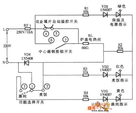
Rong Sheng CFXB50-90DA multi-purpose rice cooker circuit is shown below.
(View)
View full Circuit Diagram | Comments | Reading(1652)
CFXB50-2P electronic thermal-type rice cooker circuit
Published:2011/5/24 0:30:00 Author:John | Keyword: thermal-type rice cooker
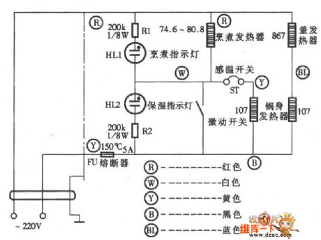
CFXB50-2P electronic thermal-type rice cooker circuit is shown below.
(View)
View full Circuit Diagram | Comments | Reading(1020)
CIC2851AE rice cooker reactor circuit
Published:2011/5/24 1:23:00 Author:John | Keyword: rice cooker reactor
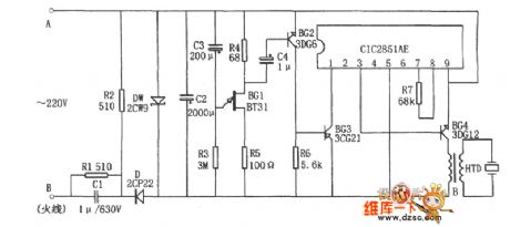
Rice cooker reactor circuit is shown in the figure. The circuit consists of 10-minute time delay circuit, 3V buck power supply, music integrated circuit CIC2851AE and piezoelectric ceramic HTD and so on. And the 10-minute delay circuit is mainly composited by BG1 R3 and C3. The 3V buck power supply mainly consist C1, R1, R2, D, DW and C2. The points A and B are parallel connected to control switch of the rice cooker.
When the rice cooker works normally, voltage on ends A and B is 0 and the entire circuit does not work. When water in rice cooker boils to dry, the master switch trips and ends A and B are given AC voltage. And the circuit begins to work. The voltage passes through the buck power supply and 10-minute delay circuit. After the delay circuit, the music integrated circuit CIC2851AE begins to work. And the output audio signal is amplified by the BG4 to drive HTD to be audible.
(View)
View full Circuit Diagram | Comments | Reading(1114)
HW-03 rice cooker and porridge device circuit
Published:2011/5/24 0:57:00 Author:John | Keyword: rice cooker, porridge device
HW-03 rice cooker and porridge device circuit is shown below.
(View)
View full Circuit Diagram | Comments | Reading(2454)
Peugeot entire vehicle circuit
Published:2011/5/24 0:34:00 Author:John
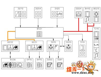
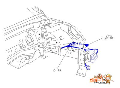
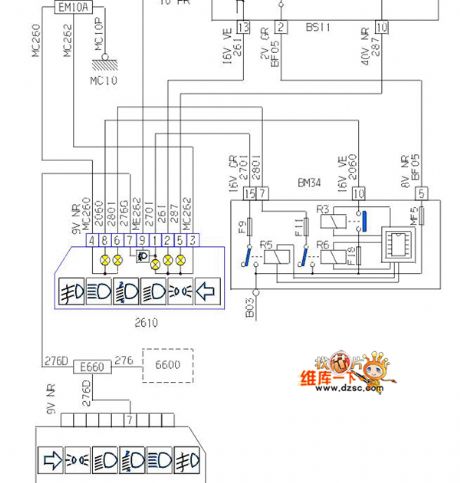
Peugeot entire vehicle circuit is shown below.
(View)
View full Circuit Diagram | Comments | Reading(755)
555 pulse electrotherapy instrument circuit
Published:2011/5/24 2:20:00 Author:TaoXi | Keyword: pulse, electrotherapy, instrument
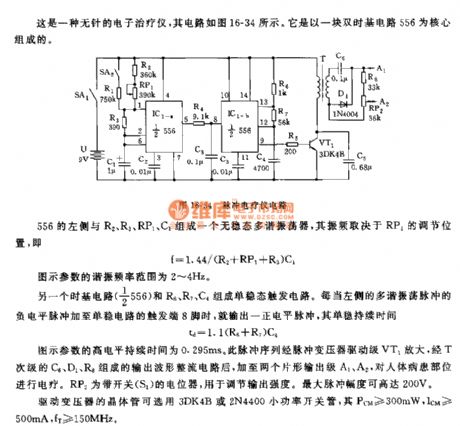
This is one kind of no needle electronic instrument, the circuit is as shown in figure 16-34, it uses a double time base circuit 556 as the core.
The astable multivibrator is composed of the left part of 556 and the R2,R3,RP1,C1, the oscillation frequency depends on the RP1's adjusting position, f=1.44/(R2+RP1+R3)C1.
Another time base circuit (1/2 556) and the R6,R7,C4 constitute the monostable trigger circuit. The figure parameter's high electrical level duration is 0.295ms. This pulse sequence is amplified by the pulse transformer driver stage VT1, and gets through the output waveform rectifier circuit which is composed of the C6,D1,R8, at last it adds to the two pieces of slice shape output stages A1 and A2.
(View)
View full Circuit Diagram | Comments | Reading(1396)
555 simple electronic massager circuit
Published:2011/5/25 1:22:00 Author:TaoXi | Keyword: simple, electronic massager
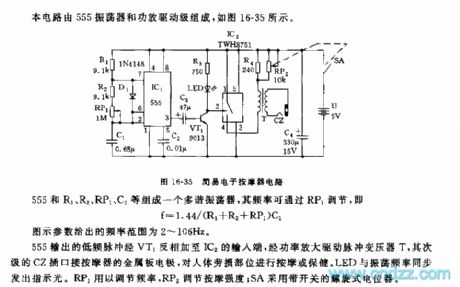
This circuit is composed of the 555 oscillator and the amplifier driving stage, as the figure 16-25 shows.
The multivibrator is composed of the 555 and R1, R2, RP1, C1, the frequency can be adjusted by RP1, f=1.44/(R1+R2+RP1)C1. The figure parameter's frequency range is 2 to 106Hz.
The low frequency pulse of 555 is reversed by VT1, and it adds to IC2's input port, then it is amplified by the power tube to drive the pulse transformer T, the subprime CZ socket connects to the metal plate electrode of massager to massage the human body strain parts. The RP1 can be used to adjust the frequency, the RP2 can be used to adjust the massage strength, SA uses the spiral potentiometer with the switch.
(View)
View full Circuit Diagram | Comments | Reading(2412)
555 simulation breathing technique information instrument circuit
Published:2011/5/24 2:35:00 Author:TaoXi | Keyword: simulation, breathing technique, information instrument
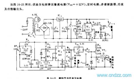
As the figure 16-25 shows, the information instrument is composed of the step-down rectifying power supply (VDD=+12V), the timing circuit, the multivibrator, the amplifier function output head.
The start timing circuit is composed of the IC1 and R1,RP1,C3, the timing time td=1.1(R1+RP1)C3. In the timing time, J closes to control the connection of J1-1,J1-2's contact points.
The controllable multivibrator is composed of the IC2 and R5, R6, RP2, C8, f=1.44/(R5+2R6+RP2)C8, you can change the frequency with the control voltage of pin-5 (RP3). VT1 uses the VMOS FET power transistor. The function output head uses the 0.85um gallium arsenide semiconductor laser, the PTC special infrared radiation ceramic material and the strong magnetic field SmCo magnet.
(View)
View full Circuit Diagram | Comments | Reading(1010)
555 blind person electronic guide audio circuit
Published:2011/5/24 2:50:00 Author:TaoXi | Keyword: blind person, electronic, guide, audio circuit
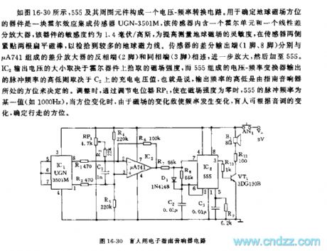
As the figure 16-30 shows, the voltage-frequency conversion circuit is composed of the 555 and the surrounding components, the device that can be used to determine the direction of the earth's magnetic field is one piece of Hall effect integrated sensor UGN-3501M, this sensor has a Hall unit and a linear differential amplifier, the sensitivity of this device is about 1.4 mV/gauss, in order to improve the sensitivity, we add two roots of flat magnetic bar on both sides of the sensor. The size of the IC2 output voltage depends on the magnetic field intensity of the Hall device, the output impulse frequency of the voltage-frequency converter which is composed of 555 depends on the charging voltage value of C2.
(View)
View full Circuit Diagram | Comments | Reading(1065)
555 smoking prohibition language warning circuit
Published:2011/5/24 3:21:00 Author:TaoXi | Keyword: smoking, prohibition, language warning
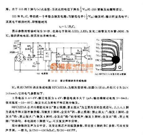
The monostable trigger circuit is composed of the 555 circuit and the R2,C1, when this circuit is triggered by the low electrical level (1/3VDD), it outputs the high electrical level, the high-level maintenance time td=1.1R2C1.
The IC2 uses the CMOS language integrated circuit HFC5221A, the soft package structure is as shown in figure (b), the shape dimension is 24mm x 14mm, it's electrical parameters are:
The operating voltage is 2.4V~5V, the rated voltage is 4.4V; the quiescent current is lower than 1uA, the output port driving current is 3~6mA, the using temperature is -10℃~60℃, the trigger mode is the high electrical level and positive pulse trigger.
(View)
View full Circuit Diagram | Comments | Reading(772)
fan cycling speed control circuit
Published:2011/5/23 20:09:00 Author:John | Keyword: fan
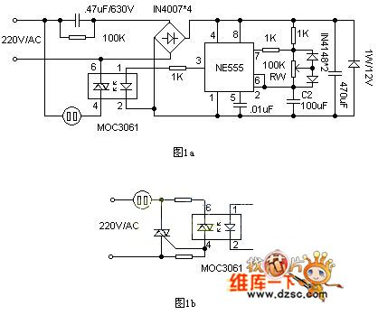
The circuit is shown in Figure 1a. NE555 in the circuit is connected as a square wave generator with an adjustable duty cycle. It can change the duty cycle through adjusting RW. When the pin 3 of the NE555 outputs in high power level, primary end of the zero-off-type optocoupler MOC3061 achieves forward current of about 10mA. And it leads the internal infrared emitting diode of gallium silicide to emit infrared light. The two-way switch in photosensitive zero-crossing detector opens when the electricity over zero. Then the power supply of the fan motor is connected. And the fan runs for air supply. When the pin 3 in the NE555 outputs in low power level, two-way switch turns off and the fan stops.
(View)
View full Circuit Diagram | Comments | Reading(2079)
Multi-function wireless remote control fan with TWH923619238 circuit
Published:2011/5/19 20:09:00 Author:John | Keyword: wireless remote control fan
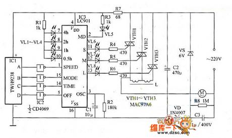
This example describes a wireless remote control fan speed controller, which is constituted by a 4 way remote control module and a fan speed control integrated circuit. It can transform an ordinary fan into a wireless remote control multi-functional speed fan.
The circuit for the receive part of the wireless remote control speed fan is shown in Figure 1. The transmitter is a four way TWH9236 key chain style transmitter. The button A of the transmitter is used for speed regulation and the button B is used for the wind mode regulation. Besides, the key C key is used for time setting and key D is for turning off the device.
(View)
View full Circuit Diagram | Comments | Reading(3519)
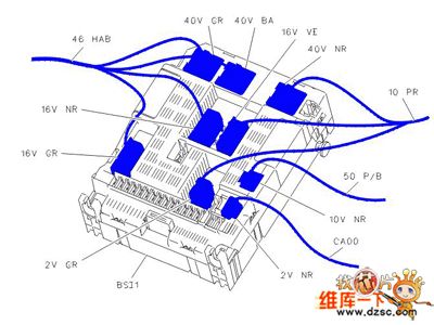
mainboard of air conditioning circuit
Published:2011/5/20 5:31:00 Author:chopper | Keyword: mainboard, air conditioning
View full Circuit Diagram | Comments | Reading(660)
Intermediate Frequency Signal Generator Circuit Made of Ceramic Filter 3L465
Published:2011/5/19 10:09:00 Author:Joyce | Keyword: Intermediate Frequency, Signal Generator, Made of Ceramic Filter 3L465
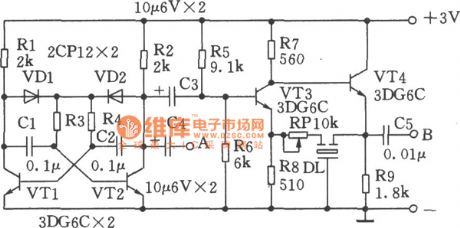
As shown in the figure is an intermediate frequency signal generator made of ceramic filter3L465.It is simple to handle and it will be esay to start oscillation.And the intermediate frequency signal produced by it is stable and have sound repeatability.It can output audio signal as well.Operating principle: VTl, VT2 and other related components constitute multivibrator with a frequency of about 400Hz.It can be used to regulate intermediate frequency signals and the audio signal can be output from point A. VT3, VT4 compose intermediate frequency signal generator, in which DL will select the frequency. Adjusting RP could change the oscillation intensity.Connecting a wire of dozens of cm long at point B can output the the modulated intermediate frequency signal.As for the multivibrator,as long as all the components are connected in the right way. oscillation will start as soon as swtiching on.
(View)
View full Circuit Diagram | Comments | Reading(789)
Eyesight Preserver (the 1st)
Published:2011/5/22 6:56:00 Author:Felicity | Keyword: Eyesight Preserver (the 1st)
Work of the circuit
The circuit consists of light examining circuit, LED shining circuit and voice prompting circuit (It is showed in picture 9-59.).
Turn on power switch S and battery GB supplies 3V voltage to the whole circuit. When the environment light is strong enough the voltage of VD is not so high. Here VL does not shine and HA makes no sound. When the environment light is dim the voltage of VD is high. Here VL shines and HA makes the sound “tick tick”. (View)
View full Circuit Diagram | Comments | Reading(602)
Car Windshield Wiper Controller (the 1st)
Published:2011/5/20 2:52:00 Author:Felicity | Keyword: Car Windshield Wiper Controller (the 1st)
Work of the circuit
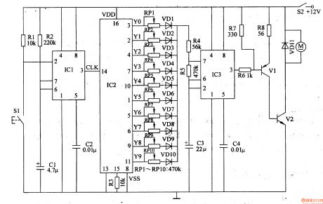
The circuit consists of One-shot trigger, Count divider, Multivibrator and motor driving circuit (It is showed in picture 7-163.).
Turn on power switch and +12V voltage supplies the working power. Press the button S1 for the first time windshield wiper motor turns over for 1s and then stops. Press the button for the second time the windshield wiper motor turns over for 2s and stops……Press the button for the tenth time the windshield wiper motor turns over for 10s and stops. (View)
View full Circuit Diagram | Comments | Reading(992)
Eye-care Photometry Machine (the 3rd)
Published:2011/5/22 7:11:00 Author:Felicity | Keyword: Eye-care Photometry Machine (the 3rd)
Work of the circuit
The circuit consists of LFO, light photometry circuit and LED indicating circuit (It is showed in picture 9-67.).
When the environmental light is too dim the value of RC is large. Here the red shining diode VL1 is lightened to remind the user to flip on the lamp. When the environmental light is suitable for reading and writing the value of RG is small. Here green shining diode VL2 is lightened. If the environmental light is too strong VL1 is lightened. (View)
View full Circuit Diagram | Comments | Reading(572)
Eye-care Photometry Machine (the 2nd)
Published:2011/5/22 7:10:00 Author:Felicity | Keyword: Eye-care Photometry Machine (the 2nd)
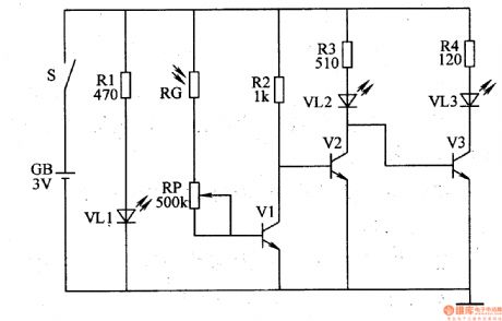
Work of the circuit
The circuit consists of power circuit, light photometry circuit and LED indicating circuit (It is showed in picture 9-66.).
Turn on the power switch S and VL1 is lightened. When the environmental light is suitable for reading and writing the value of RG is small. Here VL2 does not work while VL3 works. When the environmental light is not suitable for reading and writing the value of RG is increasing. Here VL2 starts to work while Vl3 stops. Change the value of RG to change the sensitivity of photometry. (View)
View full Circuit Diagram | Comments | Reading(530)
Eye-care Photometry Machine (the 1st)
Published:2011/5/22 7:08:00 Author:Felicity | Keyword: Eye-care Photometry Machine (the 1st)
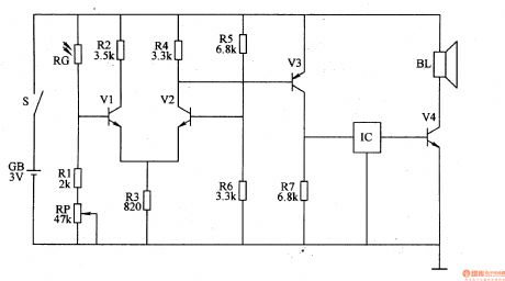
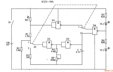
Work of the circuit
The circuit consists of photometry circuit, controlling circuit and music warning circuit (It is showed in picture 9-65.).
RG is a photometry element whose value decrease with the luminous heightening. When the environmental light is suitable for reading and writing the value of RG is small. Here IC and BL do not work. When the environmental light is not suitable for reading and writing the value of RG is increasing. Here IC works and BL makes music to remind the user to flip on the lamp. Change the value of RG to change the sensitivity of photometry.
(View)
View full Circuit Diagram | Comments | Reading(537)
| Pages:177/195 At 20161162163164165166167168169170171172173174175176177178179180Under 20 |
Circuit Categories
power supply circuit
Amplifier Circuit
Basic Circuit
LED and Light Circuit
Sensor Circuit
Signal Processing
Electrical Equipment Circuit
Control Circuit
Remote Control Circuit
A/D-D/A Converter Circuit
Audio Circuit
Measuring and Test Circuit
Communication Circuit
Computer-Related Circuit
555 Circuit
Automotive Circuit
Repairing Circuit