
Signal Processing
Index 166
Hearing-aid (the 3rd)
Published:2011/6/6 5:09:00 Author:Felicity | Keyword: Hearing-aid (the 3rd)
Work of the circuit
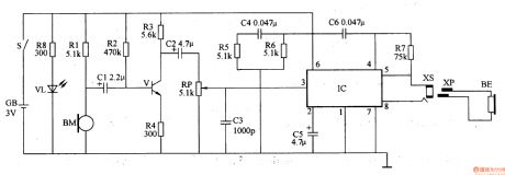
The hearing-aid circuit consists of volume amplifier circuit, capacity amplifier circuit and power indicating circuit (It is showed in picture 9-79.).
Turn on the power switch S and VL is lightened. In the same time volume amplifier circuit and capacity amplifier circuit begin to work. BM collects sound signalandthen turnsitinto faint electric signal which drives BE to make sound after being adjusted by V, RP and IC. When GB is lack of power light of VL will become faint to remind the users to change the battery. (View)
View full Circuit Diagram | Comments | Reading(3113)
Hearing-aid (the 2nd)
Published:2011/6/6 5:14:00 Author:Felicity | Keyword: Hearing-aid (the 2nd),
Work of the circuit
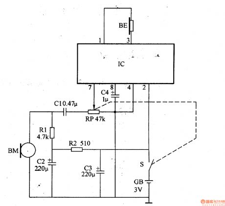
The hearing-aid circuit consists of mike BM, resistor R1 and R2, capacitor C1-C4, potentiometer RP, integrated circuit, power switch S and earphone BE. (It is showed in picture 9-78.).
BM collects the sound signal andturns itinto faint electric signal. Then the signal is inputted from IC’s pin 7 through CI and RP. At last it is returned to sound by earphone after being amplifier.
If you change the value of RP you can change the volume. (View)
View full Circuit Diagram | Comments | Reading(1745)
M50436—500SP(TV) infrared remote control reception microprocessor circuit
Published:2011/5/26 8:52:00 Author:Lena | Keyword: infrared, remote control, reception, microprocessor
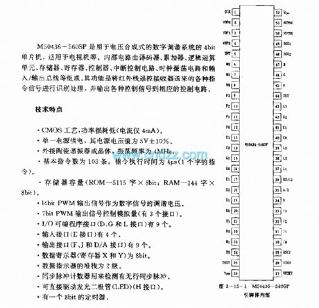
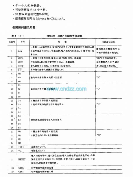
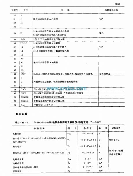
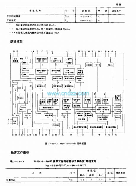
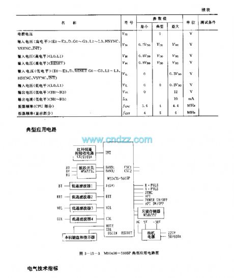
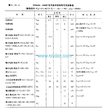
M50436-560SP are 4bit singlechips used in voltage synthesized digit tune system, applied to TV etc. Internal circuit consists of encoder, accumulator, logic operation unit, storage, register, controller, cut-off control circuit, clock oscillating circuit and input/output bus line etc. Identifing different instruction signals sentfrom infrared remote control receiver, then the circuit outputs control signals to control circuit.
technology features
CMOS technics, power loss is low(The current is only 4mA)
(View)
View full Circuit Diagram | Comments | Reading(1151)
Eye-care Lamps (the 7th)
Published:2011/6/6 5:22:00 Author:Felicity | Keyword: Eye-care Lamps (the 7th)
Work of the circuit
The circuit consists of light examine circuit and light adjusting circuit (It is showed in picture 9-74.).
When you turn on power switch the 220V AC voltage produces 2.2-2.4V DC voltage in CI. When the lamp light is weak the red diode is lightened. When the lamp light is strong enough the green diode is lightened.
You can change the value of RP2 to change the light intensity of the lamp. (View)
View full Circuit Diagram | Comments | Reading(767)
Eye-care Lamps (the 4th)
Published:2011/6/6 5:25:00 Author:Felicity | Keyword: Eye-care Lamps (the 4th)
Work of the circuit
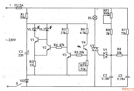
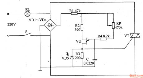
The circuit consists of power switch S, rectifier diode V1-V4, resistor R1-R3, light-sensitive diode VD5 and light EL (It is showed in picture 9-71.).
When you turn on the power switch S the 220V AC voltage is limited and reduced by EL. The voltage separates into two parts. One is supplied to the poles of VT while the other one supplies DC voltage to relaxation OSC and makes EL work. When the environmental light is strong light of ELbecomes weak. When the environmental light is weak the light of ELbecomes strong.
Change the value of RPand you canmake the change smoothly without shining. (View)
View full Circuit Diagram | Comments | Reading(530)
Eyesight Protecter (the 3rd)
Published:2011/6/6 5:21:00 Author:Felicity | Keyword: Eyesight Protecter (the 3rd)

Work of the circuit
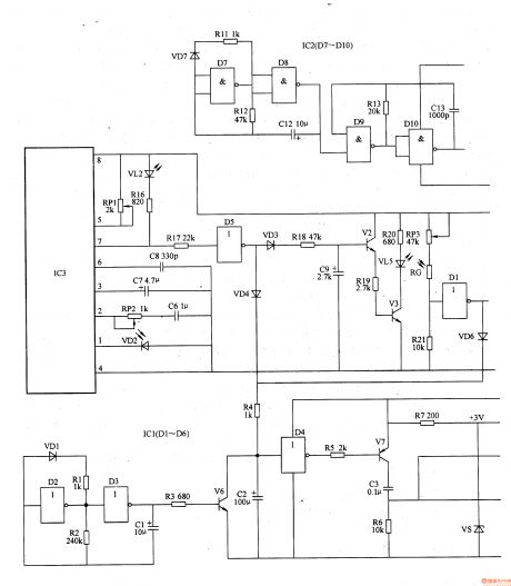
The circuit consists of power circuit, infrared launching circuit, infrared reception and amplifying circuit, light examining circuit, zero clearing pulse circuit, timing controlling circuit and acousto-optic warning circuit (It is showed in picture 9-61.).
Turn on the switch and the 220V AC voltage supplies the working power to the whole circuit after being adjusted. When the user’s head is too near from the writing pad (the distance is less than 35cm) VL2 shines and HA makes the sound “tick tick” to alarm the user. When the environment light is strong enough the voltage of VD is not so high. Here VL does not shine and HA makes no sound. When the environment light is dim the voltage of VD is high. Here VL shines and HA makes the sound “tick tick”. When the regular time is over VL3 is lightened and the HA makes sound to remind the user to have a rest. Also only if the user’s head is too near from the pad for more than 5s does the warming work. (View)
View full Circuit Diagram | Comments | Reading(538)
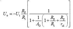
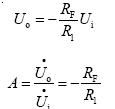
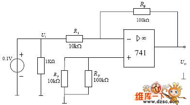
Inverting Proportional Amplifier Circuit Diagram
Published:2011/5/18 8:50:00 Author:Felicity | Keyword: Inverting Proportional Amplifier Circuit,

(View)
View full Circuit Diagram | Comments | Reading(632)
Double T Sinusoidal Oscillator with Stable Output Circuit Composed of LM170
Published:2011/5/25 4:05:00 Author:Joyce | Keyword: Double T, Sinusoidal Oscillator, Stable Output, LM170
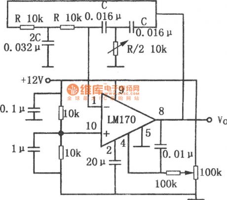
As shown in the figureis the circuit for double T sinusoidal oscillator with stable output.This circuit uses automatic gain control amplifier LM170 to stabilise its amplitude . In this way, the wave form would have no distortion. Even when the double T circuit and amplifier have changes, the output amplitude can remain constant.Using the component values in the graph can compensate the change of 40dB. 100k potentiometer is used to change the threshold level controlled by automatic gain to change the output level. The oscillation frequency of circuit is:F0 = 1/2 PI RC
If using the component values in the figure, the oscillation frequency is about 1kHz. (View)
View full Circuit Diagram | Comments | Reading(987)
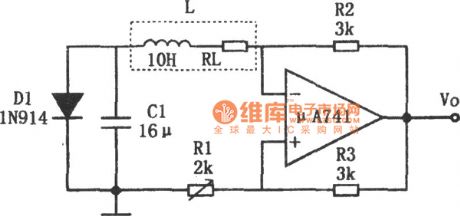
Simple Sine Wave Generator Circuit Composed of μA741
Published:2011/5/25 4:04:00 Author:Joyce | Keyword: Simple, Sine Wave, Generator, Composed of μA741

(View)
View full Circuit Diagram | Comments | Reading(637)
Stable Sinusoidal Oscillator Circuit Composed of F007
Published:2011/5/25 4:05:00 Author:Joyce | Keyword: Stable , Sinusoidal Oscillator , F007
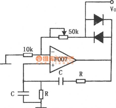
As shown in the figure is a stable sinusoidal oscillator circuit. In order to get a stable oscillation, the gain of the circuit should be 1. If the gain is too large, there will be distortion of the waveform; If gain is too small, the vibration may stop . This circuit uses two diodes to stabilize the oscillations. When the output voltage is too low, the diode will close, and the negative feedback will be cut off. Then the loop gain and the output voltage will increase.When the output goes up to a certain value, the diode will conduct, and the loop gain andoutput voltage will decrease. Repeatedly,the output amplitude will be kept in a certain value. The potentiometer in the figure is to regulate the output amplitude and the degree of distortion. The oscillation frequency of the circuit is determined by resistance R and capacitance C , the formula being :
F0 = 1/2π RC. (View)
View full Circuit Diagram | Comments | Reading(754)
Sinusoid Generator Circuit Composed of Inverter
Published:2011/5/25 4:06:00 Author:Joyce | Keyword: Sinusoid Generator, Inverter
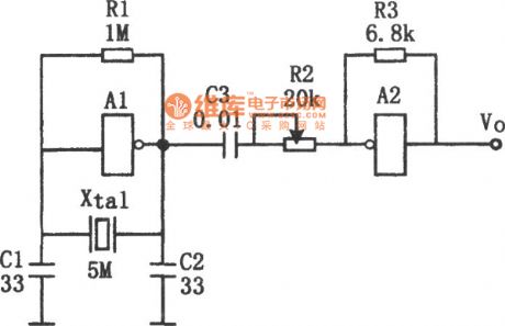
As shown in the figure is a sinusoid generator circuit composed of inverter.This circuit can get high stable sine waves above several MHZ. A1 and crystal oscillator in the figure consist a oscillating circuit . The output of A1 will export sine wave signals after passing through buffer A2. In the circuit, A1 is a linear amplifier,and the whole circuit work in a state of amplification. Due to the different characteristics of the crystal oscillators being used, output frequency and voltage of the circuit are different. R2 can be used to adjust waveform. In order to obtain accurate oscillation frequency,you can have a fine adjustment by connecting semi-variable capacitors in parallel between the ends of capacitance C1 . The oscillation frequency of circuit is determined by crystal oscillators. Change of crystal oscillators will bring out alterations in output signal frequency. (View)
View full Circuit Diagram | Comments | Reading(645)
Voltage Controlled Sinusoidal Sscillator Circuit Composed of MC1046B
Published:2011/5/25 4:07:00 Author:Joyce | Keyword: Voltage Controlled , Sinusoidal Sscillator, MC1046B
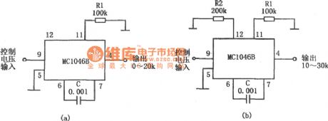
As shown in the figure ab is the voltage controlled sinusoidal oscillator circuit composed of MC1046B . When the control input voltage is 0 ~ 5V, the output can be sine wave signals with a frequency of 0 ~ 20kHz. The frequency range is determined by resistance R1 and capacitance C, so changes in resistance and capacitance can bring about alteration in oscillation frequency. If you connect resistance R2 outside the feet12 ,you can change the oscillation frequency range. If R2 = 2R1, then the oscillation frequency will be 10 ~ 30kHz. (View)
View full Circuit Diagram | Comments | Reading(612)
Broad-band Sine Wave Voltage-controlled Oscillator Circuit Composed of LF356N
Published:2011/6/6 0:21:00 Author:Joyce | Keyword: Broad-band , Sine Wave , Voltage-controlled Oscillator
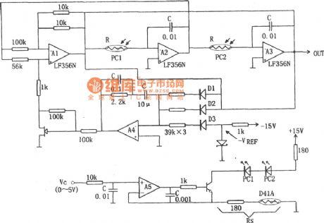
As shown in the figure is the broad-band sine wave voltage-controlled oscillator circuit. The oscillation frequency of the circuit depends on integration resistor R and capacitance C. The oscillator constitutes of resistance R controlled by an external voltage VC. The variable resistance in the circuit uses optical coupler PC1 and PC2, and the rectification circuit is detected by average value. The actual operating frequency of the circuit is above dozens of Hertz. In addition, the characteristics of control voltage VC depends on the characteristics of the photoelectric coupler used (View)
View full Circuit Diagram | Comments | Reading(1325)
Circuit of Sine wave Oscillator with Ajustable Frequency and Constant Amplitude
Published:2011/5/25 4:25:00 Author:Joyce | Keyword: Sine wave, Oscillator , Ajustable Frequency, Constant Amplitude
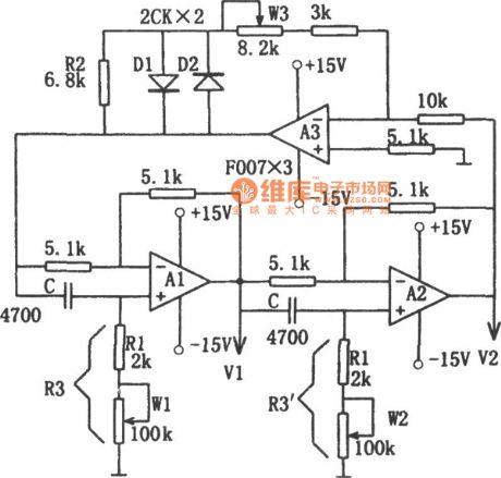

As shown in the figure is the circuit of sine wave oscillator with ajustable frequency and constant amplitude. This circuit constitutes of a two-stage phase-shifting circuit and a one-stage linear inverting amplifier, which are connected in series. And the phase-shifting circuit is composed of integrated operational amplifier A1, A2 and RC. Because the phase shift of inverter A3 is 180o, the two-stage phase-shifting circuit should also have a phase shift of 180o to ensure that it can meet the overall phase shift of 360o required by the oscillation. The dynamic resistances of diode D1, D2 are quite large when the voltage is low, so the gain of the inverting circuit composed of As is high to make sure the starting of oscillation of the circuit. Oscillation frequency of the circuit is: (View)
View full Circuit Diagram | Comments | Reading(666)
CXD3008-the integrated circuit of digital signal and servo processing
Published:2011/6/13 21:27:00 Author:Borg | Keyword: integrated circuit, digital signal, processing
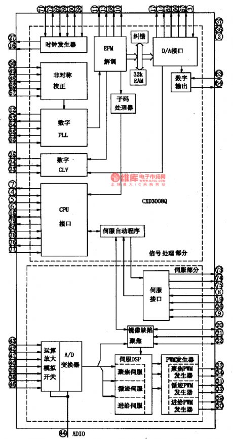
1.Function featuresCXD3008 can do demodulation to the CD, VCD and SVCD signals read out by its laser head, after handling them with super fault correcting algorithm and 32KBAM inside it, the circuit will output them as the form of CD data; in addition, it also digitally processes the signals of focus errors, tracking errors, feed errors and spindle errors in the way of repeated servo software control and wide seizing, and does auto control and auto offset control to servo circuits.
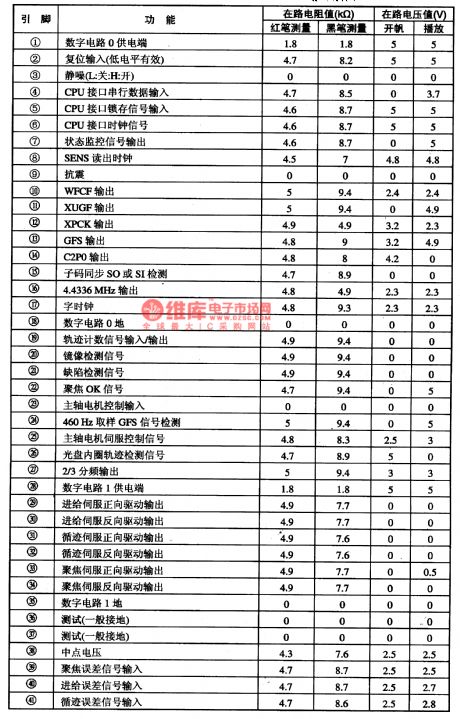
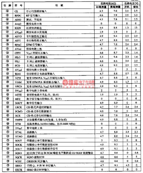
2.pin functions and data
(View)
View full Circuit Diagram | Comments | Reading(802)
The timely disinfecting, deodorizing and sterilizing circuit of 555 fridge
Published:2011/6/13 21:29:00 Author:Borg | Keyword: disinfecting, deodorizing, sterilizing
This timely disinfecting, deodorizing and sterilizing circuit of fridge can self-start and then generate ozone and air negative ions when the fridge door is open, and disinfects, deodorizes and sterilizes the inside of the fridge, when the time is over, it will automatically stops working, which is effective.The deodorizing circuit includes AC step-down voltage-steady circuit, light control timer switch circuit, high frequency oscillator and high frequency electricity discharger, etc, see as Figure 13-24.
The AC current is firstly stepped down by the capacitor of C1, and then is filtered by rectifier of C2 after passing D1~D4, finally comes out from the 3-terminal stabilizer as a +12V voltage and provides with working power supply for IC2 and IC3. (View)
View full Circuit Diagram | Comments | Reading(615)
The simple temperature control circuit of 555
Published:2011/6/13 21:30:00 Author:Borg | Keyword: temperature control
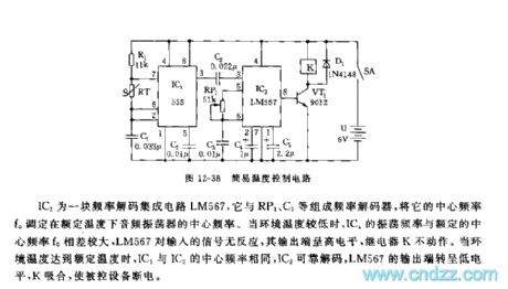
IC2 is an integrated circuit LM567 of frequency decoding, which consists a frequency decoder with RP1, C3 and so on,and its central frequency f0 is set as the central frequency of audio oscillator at the regulated temperature. When the outside temperature is too low, the difference between the vibration frequency and the regulated central frequency (f0) is noticeable, and LM567 doesn't react to the input signal, and its output terminal is in high LEV, the relay(K) is still. When the outside temperature reaches the regulated value, the central temperatures of IC1 and IC2 are the same, and IC2 decode reliably, the output point of LM567 is in a low LEV, K closes to cut off the power of the controlled equipment. (View)
View full Circuit Diagram | Comments | Reading(1162)
Use the LM386 as the sine wave oscillator circuit
Published:2011/5/25 21:44:00 Author:Christina | Keyword: sine wave, oscillator circuit
The driver alcohol detection alarm controller circuit is as shown in the figure. The QM-NJ9 is alcohol gas sensor, if it detects the alcohol odor, the resistance of QM-NJ9 between A and B will shrink, and the wiper potential of potentiometer RPl will rise up. When the voltage level is 1.6V, the ICl high-power switching device TWH8778 is connected to make the IC2 voice IC TM801 to work, the output is amplified by the IC3 integrated amplifier LM386, and then the amplified output drives the speaker BLl to send out alarm. (View)
View full Circuit Diagram | Comments | Reading(1113)
CD4093 sine wave switching to square wave circuit
Published:2011/6/9 21:19:00 Author:John | Keyword: sine wave, square wave
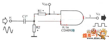
The input sine wave voltage supplies power to IC1 through the half-wave double voltage circuit, which is composed of C1, C2 and D1, D2. IC1A constitutes amplifier in order to amplify the input signal. The signal would be transformed into a square wave signal through the IC1B and IC1C. Then square wave signalis output after the amplification by IC1D, IC1E and IC1F. R2 is used to adjust the output signal amplitude. The circuit as shown can output square wave with good performance within the 20Hz-20KHz. During the application, the valid value for the input sine wave is suggested to be greater than 1.5 volts in order to ensure the quality of the output signal. Minimum input voltage sine wave must be greater than 750mV and the peak value for output signal is about 2 volts at this time.
Figure 1 sine wave switching to square wave circuit (View)
View full Circuit Diagram | Comments | Reading(4144)
FET oscillator circuit
Published:2011/5/19 0:43:00 Author:John | Keyword: FET oscillator
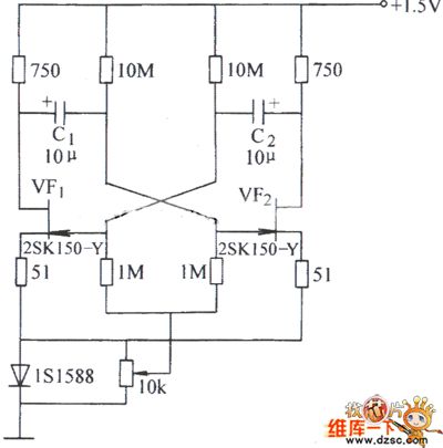
FET oscillator circuit is shown below.
(View)
View full Circuit Diagram | Comments | Reading(1135)
| Pages:166/195 At 20161162163164165166167168169170171172173174175176177178179180Under 20 |
Circuit Categories
power supply circuit
Amplifier Circuit
Basic Circuit
LED and Light Circuit
Sensor Circuit
Signal Processing
Electrical Equipment Circuit
Control Circuit
Remote Control Circuit
A/D-D/A Converter Circuit
Audio Circuit
Measuring and Test Circuit
Communication Circuit
Computer-Related Circuit
555 Circuit
Automotive Circuit
Repairing Circuit