
Amplifier Circuit
Index 201
the hardware interface circuit of DSP5402 and MAX3110
Published:2011/5/30 23:32:00 Author:Ariel Wang | Keyword: hardware, interface
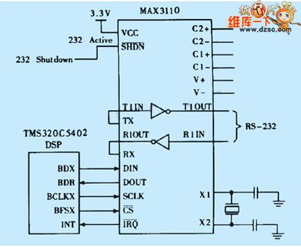
MAX3110E has full duplex communication of 16-bits data with DSP5402 through SPI port.DSP5402 sends 16-bit serial data sequence which includes transfer format CW to MAX3110,for example port setting,interruption mask,parity digit,ect.The McBSP serial interface of DSP5402 can connect directly with MAX3110 when it is SPI mode.When DSP5402's BDX1 and MAX3110's DIN is connected,it can be the sending data line.When BDR1 and DOUT is connected,itcan be the recieving data line .It sends synchronization pulse BFSX1 as the chip selecting signal.It sends clocked signal BCLKX1 as serial clock input.The hardware interface is as the chart .
(View)
View full Circuit Diagram | Comments | Reading(1242)
the watchdog and reset circuit in MSP430 SCM
Published:2011/6/1 23:36:00 Author:Ariel Wang | Keyword: watchdog, reset, SCM
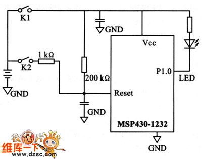
MSP430 series SCM is the new generation developed in recent years by US Texas instruments company(TI). The series is a 16-bitshybrid SCM of new concept with RISC and ultra-low power.It has ultra-low power , inner chip set outside and convenient develop method in lots of SCM series.So it becomes a shining star.It brings watchdog and reset circiut with itself.Theoretically,if the procedure has something wrong,watchdog can do the reset.But in reality,watchdog can't do everything.The experimental circuit is as the chart.
(View)
View full Circuit Diagram | Comments | Reading(1535)
The single pole sound signal generator circuit
Published:2011/6/10 3:36:00 Author:Seven | Keyword: single pole, sound signal generator
14.15 the single pole sound signal generator circuit See as Figure 14-15, the circuit is installed with an integrated oscillator circuit of 566 pressure control, and the circuit can generate a pulse train which lasts for 0.5s. The frequency of the pulse is f=1/3R1C1.
(View)
View full Circuit Diagram | Comments | Reading(590)
The headphone of conductivity hearing aids
Published:2011/6/10 3:37:00 Author:Seven | Keyword: conductivity hearing aids
Generally, the headphones of hearing aids are put on the ears, so to most of the deaf, the devices are useless. Here, this headphone is hold in the mouth, and the the sound spreads along the teeth(or in the bone conduction way), which makes the ill acquire sounds again. Construction Principles Sound waves spread to the eardrum and the ear bone through the external acoustic meatus, and then stimulate the auditory sensor in the cochlear. This conduction method is called air conduction . Besides, wave quakes can reach the internal ear through the head bones(such as the mastoid process and the tooth). (View)
View full Circuit Diagram | Comments | Reading(580)
The circuit of the snore and dream language therapeutic apparatus
Published:2011/6/10 3:38:00 Author:Seven | Keyword: dream language, therapeutic apparatus
This circuit can effectively stop snoring and dream language when sleeping, after some time of using, people get conditioned reflex, so they can overcomes these ailments gradually. As long as people generate the snoring sound or talk in the dream, the circuit will emit electric pulse of prod feeling, then the ill will wake up, so snoring and dream language can be stopped.
Working Principles See as figure 1. When the microphone MIC sense the sound of snore or talk, the sound is coupled to VT1 and VT2 by C, and then it is magnified by the integrated amplifier, the signal voltage is output by RP after it is raised by T. (View)
View full Circuit Diagram | Comments | Reading(515)
The fly-killing device circuit
Published:2011/6/10 3:39:00 Author:Seven | Keyword: fly-killing device
Working principlesThe circuit of the device is shown in Figure. The whole device is directly powered by the mains voltage of 220V which has been rectified. R3,R4,R5,C1 and the dual-base electrode consist a relaxation oscillator. Uncontrollable silicon is in the off state, after being rectified by VD and then runs across the equivalent resistors of R6 and L1, the mains charges C3. When VS is triggered and conducting, the electric charge on C3 discharge immediately by the conducting silicon and the equivalent resistor of L1. When the charging current becomes 0, the controllable silicon blocks automatically. (View)
View full Circuit Diagram | Comments | Reading(629)
The electric gas igniter circuit
Published:2011/6/10 3:40:00 Author:Seven | Keyword: igniter circuit
Working Principles See as figure 1, the circuit consists of the oscillator, high-voltage rectifier and booster. The oscillator consists of a triode VT and L1,L2 and R of T1, once the power supply switch of S is on, VT will be oscillating, the a high voltage will be sensed at the L3 sensing pole of T1, and it charges the capacitor C after being semi-wave rectified by diode VD, in the meantime, L5 pole of T2 is sensing a higher electric pulse and engaging in igniting. When S was pulled to 2 gear, the electric charge will keep discharging till the gas is lighted reliably. (View)
View full Circuit Diagram | Comments | Reading(819)
The principle diagram of simple Ni-cd chargers
Published:2011/6/9 0:05:00 Author:Seven | Keyword: Ni-cd charger
The principle diagram of simple Ni-cd chargers (View)
View full Circuit Diagram | Comments | Reading(610)
The infrared emitting circuit
Published:2011/6/10 3:40:00 Author:Seven | Keyword: infrared emitting circuit
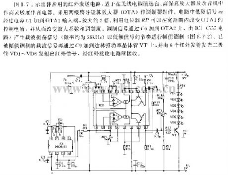
In Figure 8.7 is the sound infrared emitting circuit, which is used in wireless electric modulating station selectors, high-fidelity amplifiers and recorders, as the high sensitive sound equipment. The circuit is fixed with OTA as the modulating component. In the circuit, lower-frequency signal UE is delivered to the input point by capacitor of C1, and it is magnified to 2 times. By the potentiometer RP, the control current of OTA1 can be changed in a wide range, so that the magnifying parameter and modulation degree can be changed. The modulation signal is added to OTA2 by C6.
(View)
View full Circuit Diagram | Comments | Reading(588)
The pulse width modulation circuit
Published:2011/6/10 3:46:00 Author:Seven | Keyword: pulse width, modulation circuit
About the pulse width modulation circuit, we should first analyse the circuit. If the pulse is 3uS/5V, the normal state of Q4 is closed, and 3uS is conducting at the moment of starting to work. Therefore, Q5 is normally conducting, and closed in transiency. This seems no the same with what xbtxbt said. So after the initial analysis, the possible consequence is: 1.the working principle is wrong; 2. The circuit is drawn wrongly; 3.see as the figure, the input signal is input wrong.By the direction of diode D21, we guess that 3 may be right.Firstly, we assume that the 3 is right. (View)
View full Circuit Diagram | Comments | Reading(667)
The voice recorder circuit
Published:2011/6/9 0:09:00 Author:Seven | Keyword: voice recorder
View full Circuit Diagram | Comments | Reading(1097)
The circuit of air anion generator
Published:2011/6/10 1:09:00 Author:Seven | Keyword: air anion generator
Air anion generatorAir anion generator increases the air anion content by using high voltage electric corona, so that the air is improved and health is promoted, the anions are called air vitamin . The MSc advanced clinical practitioner proves that it can assist to cure the illnesses of respiratory system, circulatory system and nervous system, etc, so it is widely used in the life and medical area.This text is to introduce an effective and open air anion generator, which uses controllable silicon inverted high voltage and suspended discharge needle.
(View)
View full Circuit Diagram | Comments | Reading(741)
The power supply of Jinxing C6458
Published:2011/6/10 1:02:00 Author:Seven | Keyword: power supply, Jinxing
Oscillating process:After being stepped down by R804 and TH803, and then stabilized by ZD801, the 220v AC current becomes a voltage of about 12V, and it is delivered to 16-pin of IC801 by D806 and R806 as the oscillation starting voltage, when the voltage on 16-pin is higher that 10.3v, the circuit starts to oscillate. The 14-pin outputs the motivating pulse which is added to the base electrode by D817,D819~D821, and a 300v DC voltage is imposed on the 1-pin of the switch transformer, the integrated pole of Q801 is connected with 3-pin of the switch transformer, then a AC pulse current is generated between 1-pin and 3-pin. (View)
View full Circuit Diagram | Comments | Reading(551)
The principle circuit of classical Motorola L7 cellphone (1/7)
Published:2011/6/9 0:10:00 Author:Seven | Keyword: principle circuit, Motorola
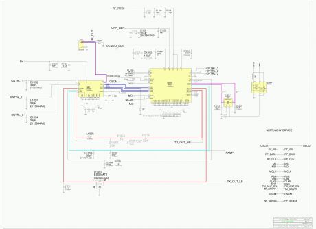
View full Circuit Diagram | Comments | Reading(766)
The absolutely available switch power supply: Panasonic M12H power supply
Published:2011/6/10 1:05:00 Author:Seven | Keyword: switch power supply, Panasonic
The power supply is used in Panasonic color TV of TC-230H、TC-2030DHN、TC-830D、TC-840D, etc.
Oscillating processThe DC voltage on C836 runs across P1 and P2 coils of T801, and the reaches C pole of the internal switch of IC801 1-pin, in the mean time, it is imposed on B pole of the internal switch of IC801 2-pin by R803, the switch pipe starts to conduct, and the current of E pole runs out from 4-pin of IC801. The current in P1 and P2 coil of T801 is rising and generates sensing signals, the signals are coupled with F2 and F3, at the moment, the sensing voltage polarity of F2 is positive, while F3 is negative. (View)
View full Circuit Diagram | Comments | Reading(736)
The absolutely available switch power supply: Panasonic L15 power supply
Published:2011/6/10 1:07:00 Author:Seven | Keyword: power supply, Panasonic
Oscillating circuitThe DC voltage of 300v on C847 run across the primary coils,P1 and p2, of the energy saver transformer, and then it is imposed on C pole of the internal switch of IC801 3-pin, in the meantime, it is imposed on B pole of the internal switch of IC802 2-pin by R803, so that the switch pipe is conducting. Therefore, the voltage in P1 and P1 coil is coupled with F2 and F3, and the positive feedback is imposed on the 2- and 4-pin(i.e the B- and E-pin of the internal switch pipe) of IC801 by C806 and R804, which makes the switch pipe saturated.
Stabilized circuitThe stabilized circuit is completed in STR50213. (View)
View full Circuit Diagram | Comments | Reading(624)
The absolutely available switch power supply: Sanyo 83P power supply
Published:2011/6/10 1:10:00 Author:Seven | Keyword: switch power supply
Oscillating process:When BG311 is saturated, the current in coils of 4 and 6 is linearly magnified and B301 is saving the field power. The current on E pole of BG311 runs across R330 and generates a linearly magnified sawtooth voltage, the the voltage runs across the 2-pin of A301 by C330 and makes the two control pipes in the 2-pin conducting, after the current on B pole of BG311 is distributed by 3-pin of A301, while the voltage on the negative pole of C330 is also added to the B pole of BG311 by A301 2- and 3-pin, finally, bg311 quits from the saturated state. (View)
View full Circuit Diagram | Comments | Reading(554)
The absolutely available switch power supply: Sanyo 80P power supply
Published:2011/6/10 3:47:00 Author:Seven | Keyword: power supply, Sanyo
Oscillating process:The 300v voltage is imposed on the B pole of switch Q504 by R518 and R519, and Q504 starts to conduct. The 9- and 10-pin of T501 are positive feedback coil, the voltage polarity of 9-pin is positive, while 10-pin is negative. Due to the positive feedback which consists of the B and E pole, R516, R515 and D509, Q504 is saturated quickly.After Q504 is saturated, the current in the primary coil of T501 rises up linearly, the current generates a sawtooth-wave step-down voltage on R514, the voltage is delivered to the B pole of Q502 by R505 and C507, and the sawtooth wave voltage is added on the 6.8V DC voltage of Q502B. (View)
View full Circuit Diagram | Comments | Reading(571)
The absolutely available switch power supply: Hitachi NP8C power supply
Published:2011/6/10 3:47:00 Author:Seven | Keyword: power supply, Hitachi
Oscillating process:The voltage of 300V is imposed on the B pole of pipe Q901 by R911,R907 and R908, then Q901 starts to conduct and the primary coil of T901 begins to have current, in the meantime, a sensing voltage is generated, the polarity of the upper part is positive and the lower part is negative, so that the coil also begins to generate a sensing voltage, and the polarity of upper part is negative and the upper part is positive, the voltage is delivered to B pole of Q901 by R902, R909 and C908, which makes Q901 more conducting, so the positive feedback makes Q901 saturate quickly. During the time of saturating, D906 and D907 are blocked and T901 is saving energy, at the moment, the positive feedback voltage is charging C908 continuously. (View)
View full Circuit Diagram | Comments | Reading(596)
The absolutely available switch power supply: Hitachi NP84C power supply
Published:2011/6/10 1:14:00 Author:Seven | Keyword: power supply, Hitachi
Oscillating process: The DC voltage of about 300V is imposed on the B pole of pipe Q901 by R902, R903 and C905, then Q901 starts to be conducting, then the current on C pole flows through the 1- and 3-pin of the T901 primary coil, a sensing EMF is generated and coupled with the 5- and 10-coil, which generates a sensing voltage that the upper is positive and the lower is negative, the voltage is delivered to B pole of Q901 by R905, C911, R906 and C908, so the current of Q901 is magnified further, the positive feedback makes Q901 saturated and conducting quickly. During the time of saturating, the current in 1- and 3-pin of T901 is rising linearly. (View)
View full Circuit Diagram | Comments | Reading(639)
| Pages:201/250 At 20201202203204205206207208209210211212213214215216217218219220Under 20 |
Circuit Categories
power supply circuit
Amplifier Circuit
Basic Circuit
LED and Light Circuit
Sensor Circuit
Signal Processing
Electrical Equipment Circuit
Control Circuit
Remote Control Circuit
A/D-D/A Converter Circuit
Audio Circuit
Measuring and Test Circuit
Communication Circuit
Computer-Related Circuit
555 Circuit
Automotive Circuit
Repairing Circuit