
Amplifier Circuit
Index 217
MC3359-Narrow band FM ZF integrated circuit diagram
Published:2011/5/22 1:43:00 Author:leo | Keyword: MC3359-Narrow band FM ZF integrated circuit diagram
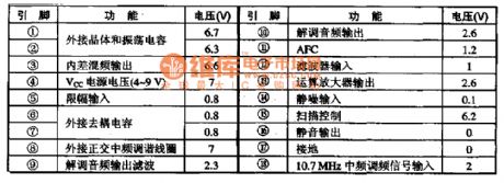
MC3359 is a type of narrow band FM ZF integrated circuit which applies to frequency modulation of ZF circuit in duplex operation communication devices.
1.Function features:The integrated circuit MC3359 contains mixer circuit, oscillator, amplitude limiter, noise limitation detection, demodulator and other circuits.
2.Pin functions:MC3359 has two kinds of packages: one is 18-pin dual lie and the other is 20-pin patch(1 and 20 are NC while 2 to 19 pin correspond 1 to 18 pin). The picture gives all detailed information about the 18 pins. (View)
View full Circuit Diagram | Comments | Reading(1279)
Power Amplifier Circuit Diagram Formed by CA3094 and Others
Published:2011/5/20 22:28:00 Author:leo | Keyword: Power Amplifier Circuit Diagram Formed by CA3094 and Others, CA3094
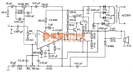
As what is shown in the picture, this is a power amplifier circuit which is made up of CA3094 and others. CA3093 contains a output transistor with the maximum output current of 100mA and OTL audio amplifier used for 8Ω load with bootstrap transistor as well as tone control circuit and so on. In the circuit, VT2 and VT3 can form a complementary type emitting following bootstrap circuit. VT1 offers biasing and compensates temperature, which also decides the operating point of AB type amplifiers. C2 is bootstrap capacitor which is used to improve the drive voltage of amplifier. Tone control circuit is located in the load feedback circuit of operating amplifier to acquire better frequency feature. (View)
View full Circuit Diagram | Comments | Reading(2512)
MC13135-Wireless receiving demodulation integrated circuit diagram
Published:2011/5/21 22:12:00 Author:leo | Keyword: MC13135-Wireless receiving demodulation integrated circuit diagram
MC13135 is a type of receiving demodulation interated circuit which is applied in receiving demodulation of antenna in communication.
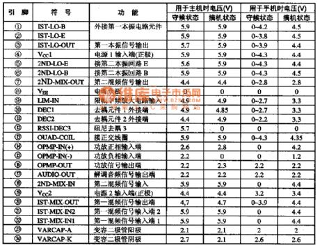
1.Function features:The integrated circuit MC13135 consists of dual conversion circuit, local oscillator circuit, mixer circuit, filed intensity detection circuit, audio pre-amplifying circuit, medium frequency signal amplifying circuit and other related circuits.
2.Pins functions and data:The integrated circuit MC14433 adopts 24-pin dual line package. The arrangement and functions of its pins are as what is shown in the picture.
Note: If it cannot receive wireless signals, please check whether 22 pin of MC13135 can receive signals or not. If it is ok, please check whether the dual conversion signals of 18 pin is common or not. (View)
View full Circuit Diagram | Comments | Reading(1020)
555 learning time too long reminding circuit
Published:2011/5/23 7:31:00 Author:TaoXi | Keyword: learning time, too long, reminding circuit
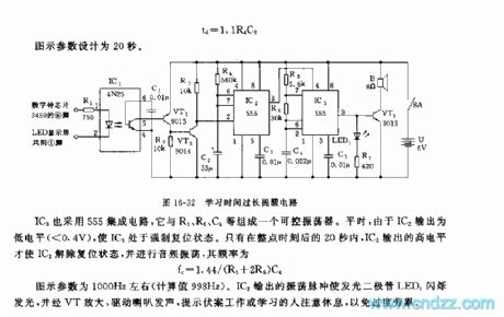
This learning time reminding circuit will remind you every one hour when you are learning or working to protect the eye and the body. This circuit is composed of the integral point lightspot coupler, the trigger control circuit and the controllable audio oscillator.etc. The circuit is as shown in figure 16-32.
The integral point is led out by the digital clock tenths unit LED digital tube's b segment. Under the action of the integral point moment jumping signal, the IC1's phototransistor has the low resistance, VT1 conducts, VT2 is in the saturated conduction state.
IC2 uses the time base circuit 555, and the monostable trigger is composed of the time base circuit 555 and the R2,C2.
(View)
View full Circuit Diagram | Comments | Reading(709)
Accurate FM tuning indicator circuit
Published:2011/5/20 2:44:00 Author:Christina | Keyword: Accurate, FM, tuning, indicating circuit
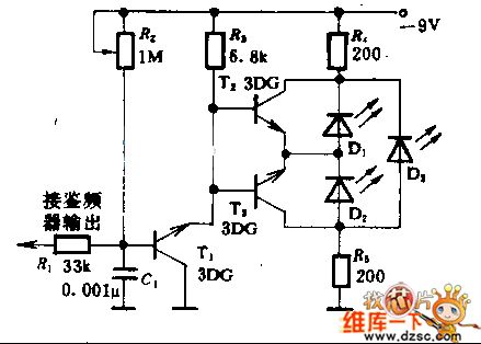
This indicator can prompt the tuning state by adjusting the discriminator's DC output to zero.
The key point of the circuit debugging is the T1's operating point, you can use the millvolt meter to oversee the DC output, to adjust the receiver to the FM radio station, then change R2 to make D3 in the brightest state.
(View)
View full Circuit Diagram | Comments | Reading(2651)
The monostable trigger circuit composed of the 555
Published:2011/5/19 20:58:00 Author:Christina | Keyword: monostable trigger
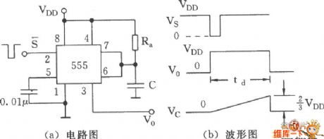
The monostable trigger circuit composed of the 555 is as shown. Each function port is corresponding to this figure. The timing network is composed of the monostable trigger circuit, the resistance Ra and the capacitor C. (View)
View full Circuit Diagram | Comments | Reading(567)
refrigeration equipment temperature control circuit composed of the LM3911 monolithic temperature control integrated circuit
Published:2011/5/16 10:12:00 Author:Christina | Keyword: refrigeration equipment, temperature control, monolithic
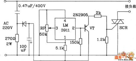
The refrigeration equipment temperature control circuit composed of the LM3911 monolithic temperature control integrated circuit is as shown:
(View)
View full Circuit Diagram | Comments | Reading(955)
RAM extension method circuit of AVR
Published:2011/5/19 18:30:00 Author:Christina | Keyword: extension method, RAM
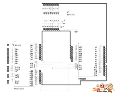
RAM extension method circuit of AVR is as shown:
(View)
View full Circuit Diagram | Comments | Reading(718)
AN7105-The integrated reproducing circuit of single door stereo
Published:2011/5/19 1:06:00 Author:Borg | Keyword: integrated reproducing circuit, single door stereo
1.the internal circuit and pin functions of AN7105AN7105 consists of two lines of pre-amplifiers and balancers, and its pin functions and data are listed in Table 1.
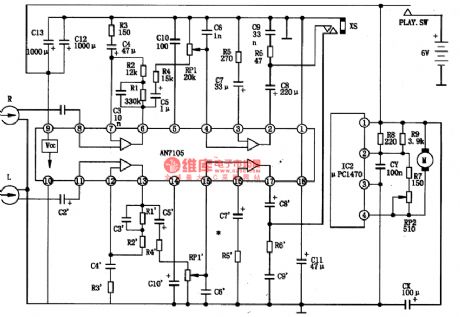
2.the typical application circuit of AN7105
The typical application circuit of AN7105 is as shown in Figure 1.
3.signal courseMagnetic head signals come in from pins of (11) and ⑧, after magnifying and frequency compensation, they come out from (13) and ⑥, then they come in through (15) and ④ after the volume is magnified. Finally, the signals are output from (15) and ④, and the headphone is driven to generate sound. (View)
View full Circuit Diagram | Comments | Reading(1393)
AN7085N5-the integrated recording circuit of single door
Published:2011/5/19 6:01:00 Author:Borg | Keyword: integrated recording circuit, single door
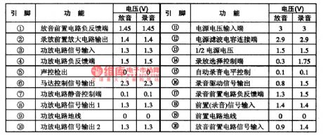
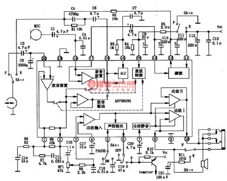
AN7085N5 is an integrated recording circuit of single door, which is produced by Panasonic. It is used in low voltage radios and the same kind of stereo systems.1.The internal circuit and pin functions of AN7085N5AN7085N5 contains sub-circuits of pre-amplifier, recording drive, recording/reproducing transmission, power amplifier,ACL and mute power amplifier,etc.The IC is in 20-lead dual line plastic package,and its pin functions and data are listed in Table 1.
Table 1 pin functions and data of AN7085N52.the typical application circuit of AN7085N5
(View)
View full Circuit Diagram | Comments | Reading(580)
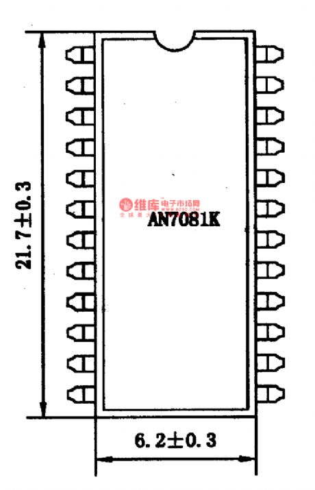
AN7081K-the integrated reproducing circuit of single door stereo
Published:2011/5/19 6:07:00 Author:Borg | Keyword: integrated reproducing circuit, single door
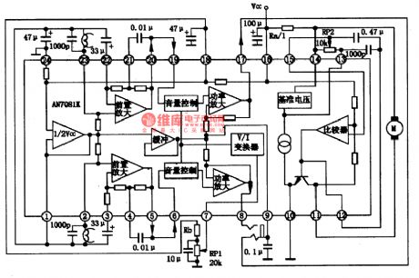
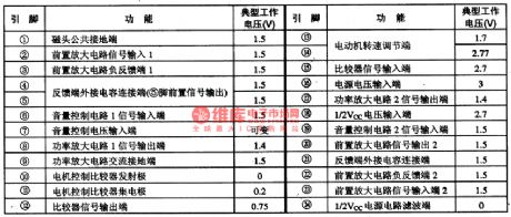
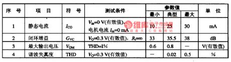
1.the function feature of AN7081K(1)there is a motor-steady circuit(equal to AV6550), so one chip can fulfill all the functions of a common radio. It is convenient to use, while the earlier two generations need a outer motor-steady circuit.(2)The 6 resistances in both right and left channels of the preset balance amplifier circuit are fixed in the IC, so 6 outer resistances are not necessary any more.(3)The output GL capacitor (220μF), shock eliminating capacitor(0.033μF) and negative feedback capacitor(1OμF) of power amplifier stage are removed, so 6 capacitors in total are saved.
(View)
View full Circuit Diagram | Comments | Reading(1213)
AN7060-The integrated circuit of preset audio motivation
Published:2011/5/19 6:12:00 Author:Borg | Keyword: integrated circuit, preset audio motivation
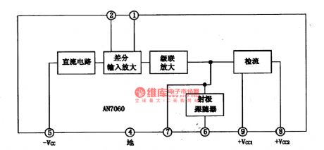
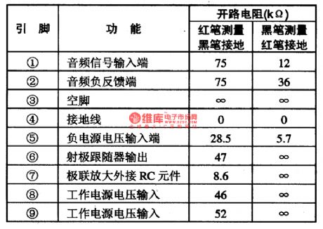
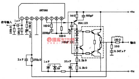
AN7060 is an integrated circuit of preset audio motivation produced by Panasonic, which is used in HI-FI stereos.1.the internal circuit and pin functions of AN7060AN7060 is an integrated circuit of high-pressure-proof preset audio, which is used to motivate a power amplifier of 60w, and it characterizes with low noise and litter distortion. The IC is in 9-lead single line package, whose internal circuit is as shown in Figure 1, and its pin functions and data are listed in Table 1.
Figure 1 the internal circuit of AN7060
Figure 1 the internal circuit of AN7060
(View)
View full Circuit Diagram | Comments | Reading(5397)
AN7108-the integrated reproducing circuit of single door stereo
Published:2011/5/18 8:35:00 Author:Borg | Keyword: reproducing circuit, single door stereo
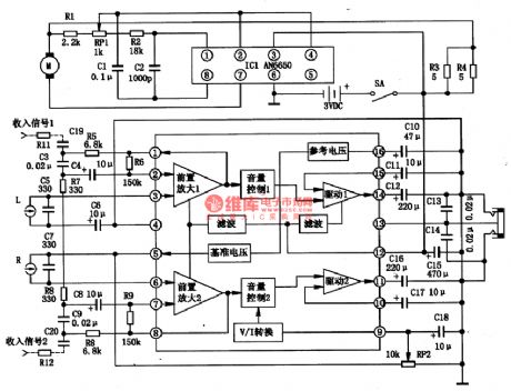
AN7108 is in 16-lead dual in-line package, which is formed by two same channels, and each channel consists of preamplifier, volume control and headphone drive power amplifier circuit. The V ref wave filter and bias circuit in the circuit have good ripple contain factors, and they can normally work without any adjustment. Besides, just a potentiometer could control the electric pressure controlled stereo volume, and it overcomes the frictions noise, the pressure controlled amplifier consists of drives.
(View)
View full Circuit Diagram | Comments | Reading(1031)
The servo driven circuit of AN8389SE1
Published:2011/5/18 20:28:00 Author:Borg | Keyword: servo driven
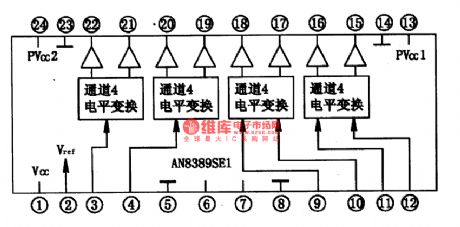
AN8389SE1 is an integrated single door circuit of laser head servo driver produced by Panasonic, which is widely used in VCD,SVCK,CVD and DVD players.1.the internal circuitAN8389SE1 contains a 4-channel BTL drive circuit, which can directly convert digital servo control signals into the drive output of servo executing parts. The internal circuit of it is shown in Figure 1.
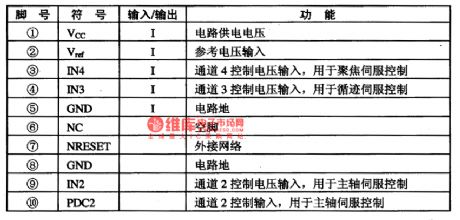
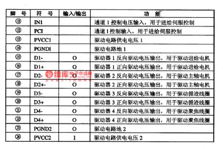
Figure 1. The internal circuit of AN8389SE12.Pin functionsPin functions of AN8389SE1 are listed in Table 1.
(View)
View full Circuit Diagram | Comments | Reading(957)
Single Power And Low Power Consumption Instrument Amplifier Circuit Composed Of INA102
Published:2011/5/19 9:40:00 Author:Robert | Keyword: Single Power, Low Power Consumption, Instrument Amplifier
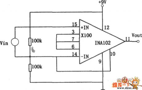
The single power and low power consumption instrument amplifier circuit is shown in the picture below. This circuit uses the low power consumption instrument integrated amplifier INA102, whose internal resistance has excellent temperature performance and working stability. There are two 100kΩ resistance in the picture making up a voltage divider (to divide the power voltage). It makes the out-phase input port have a 4.5V DC voltage. So when there is no input signal its output voltage is still DC 4.5V. Its voltage magnification times would be 100 according to the circuit connection in the picture.
(View)
View full Circuit Diagram | Comments | Reading(721)
Precise Isolation Instrument Amplifier (INA102) Circuit
Published:2011/5/19 9:57:00 Author:Robert | Keyword: Precise, Isolation, Instrument, Amplifier
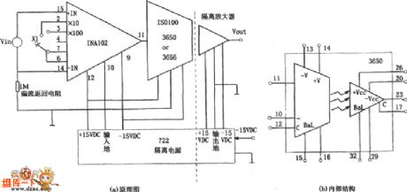
The precise isolation instrument amplifiercircuit is shown in the picture below. From the picture, this circuit's first stage uses the gain-variable instrument amplifier INA102, Andthe back stage can usea isolation amplifier such as coupled linear amplifier ISO100 or 3650. Also it can usethe transformer coupled isolation amplifier 3656. Its power supply uses 722 type isolation power.
(View)
View full Circuit Diagram | Comments | Reading(602)
High-Precision High-Impedance Instrument Amplifier Circuit Composed Of OPA2111
Published:2011/5/19 7:42:00 Author:Robert | Keyword: High-Precision, High-Impedance, Instrument, Amplifier
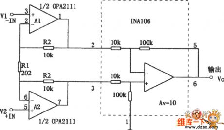
The High-Precision High-Impedance Instrument Amplifier Circuit Composed Of OPA2111 is shown in the picture. The circuit in the picture's total voltage magnification times is Av=10×(1+2R2/R1)=1000 times. The back stage uses a differential amplifier circuit whose gain is 10. This would expand the instrument amplifier's input common-mode voltage range tobe ±10V.
(View)
View full Circuit Diagram | Comments | Reading(747)
BA6286N-the bilateral control integrated circuit of motor drive
Published:2011/5/17 20:47:00 Author:Borg | Keyword: bilateral control, integrated circuit
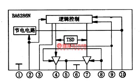
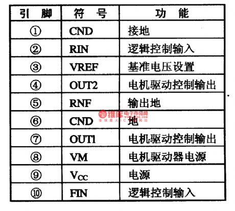
BA6286N is a bilateral control integrated circuit of motor drive produced by Toyo Corp., which is used in CD ,VCD,SVCDand VCD players as motor drivers.1.the internal circuitBA6286N contains logic control circuit and energy-saving circuit, which can provide drive current of 100Am, and its internal circuit is as shown in Figure 1.
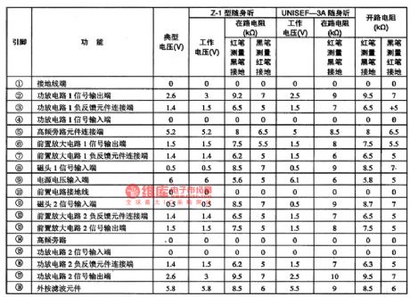
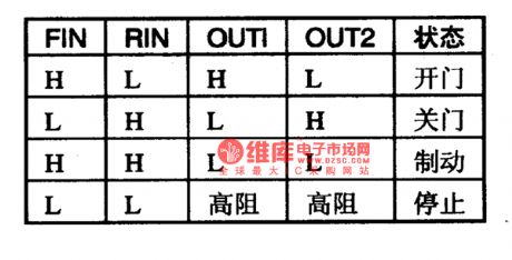
2.pin functionsBA6287N is in 10-lead single line package, whose pin functions are listed in Table 1.Notes: the logic control values of BA6287N are listed in Table 2, by which we can judge if IC is malfunctioning.
(View)
View full Circuit Diagram | Comments | Reading(872)
GD9915-an integrated microcomputer circuit of communication single door
Published:2011/5/13 6:27:00 Author:Borg | Keyword: microcomputer, communication single door
GD9915 is an integrated microcomputer circuit of communication single door, which is used in caller display phones.Function featuresGD9915 is a four bit microprocessor, which can not only control the reception, handling and displaying data of call FSK and DTMF, but also has other functions like pulse/two-tone coupling dialing and so on. (1) it contains FSK decipherers which are conforming to BELL202 and ITU-TV23. (2) it contains LCD drive and control circuits, which can directly drive the LCD display.
(View)
View full Circuit Diagram | Comments | Reading(542)
BA3503F-the integrated reproducing circuit of single door stereo
Published:2011/5/18 23:50:00 Author:Borg | Keyword: integrated reproducing circuit, single door
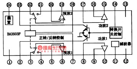
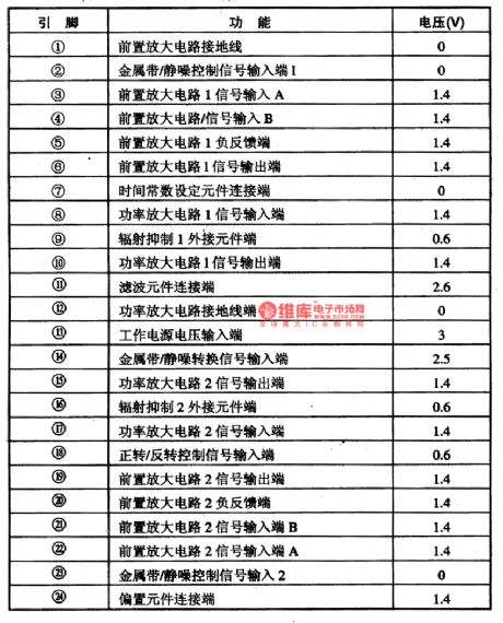
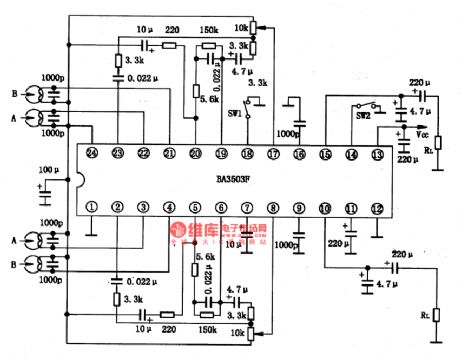
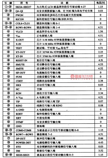
BA3503F is an integrated reproducing circuit of single door stereo produced by Toyo Power Tool Corp., Japan, which is an integrated preamplifier of 4-input auto-switching dual-channel. It is fit for small-sized low-voltage auto-reversing radios. 1.the internal circuit and pin functions of BA3503F BA3503F contains 2-channel preamplifier and separated 2-channel power amplifier circuit, whose internal circuit is shown in Figure 1. It is in flat 24-lead dual line package, and its pin functions and data are listed in Table 1.
(View)
View full Circuit Diagram | Comments | Reading(954)
| Pages:217/250 At 20201202203204205206207208209210211212213214215216217218219220Under 20 |
Circuit Categories
power supply circuit
Amplifier Circuit
Basic Circuit
LED and Light Circuit
Sensor Circuit
Signal Processing
Electrical Equipment Circuit
Control Circuit
Remote Control Circuit
A/D-D/A Converter Circuit
Audio Circuit
Measuring and Test Circuit
Communication Circuit
Computer-Related Circuit
555 Circuit
Automotive Circuit
Repairing Circuit