
Amplifier Circuit
Index 215
ML15L movement protection circuit
Published:2011/5/26 8:12:00 Author:Christina | Keyword: movement, protection
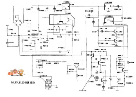
The ML15L movement protection circuit is as shown:
(View)
View full Circuit Diagram | Comments | Reading(685)
DC fluorescent circuit
Published:2011/5/30 0:45:00 Author:Christina | Keyword: DC, fluorescent
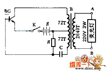
This circuit is composed of three components and a transformer, it has the features of simple structure, high efficiency, low power consumption and durable.
(View)
View full Circuit Diagram | Comments | Reading(594)
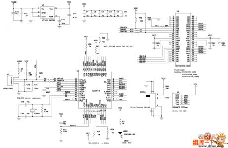
U disk circuit principle diagram
Published:2011/5/26 8:13:00 Author:Christina | Keyword: U disk, circuit principle
View full Circuit Diagram | Comments | Reading(690)
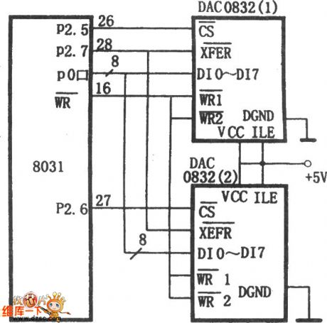
DAC0832 and 8031 double buffers synchronous way interface circuit
Published:2011/5/26 7:56:00 Author:Christina | Keyword: double buffers, synchronous way, interface circuit
View full Circuit Diagram | Comments | Reading(680)
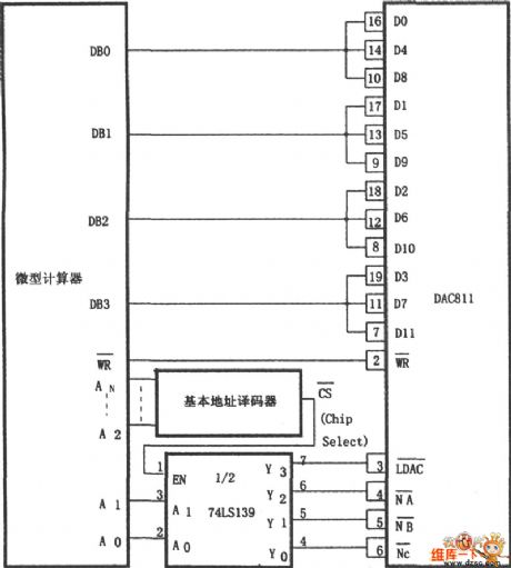
DAC811 and 4-bit microcomputer interface circuit
Published:2011/5/26 7:59:00 Author:Christina | Keyword: 4-bit, microcomputer, interface circuit
View full Circuit Diagram | Comments | Reading(625)
AD574A and the SCM interface circuits
Published:2011/5/26 2:27:00 Author:Christina | Keyword: SCM, interface
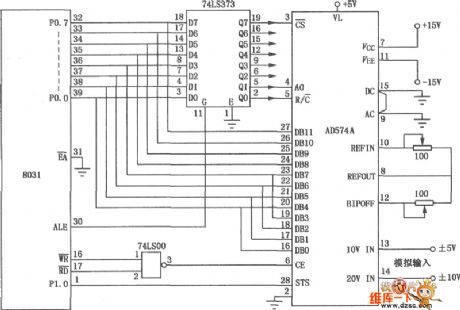
The SCM interface circuit which is composed of the AD574A is as shown. This circuit uses the AD574A type 12-bit gradually comparative type A/D converter, also it has the mixed integration type conversion chip which is composed of two pieces bipolar type circuit, the precision and speed is high, it is one kind of A/D converter that can be used in wide range of applications, also the interface circuit which is composed of it. (View)
View full Circuit Diagram | Comments | Reading(1084)
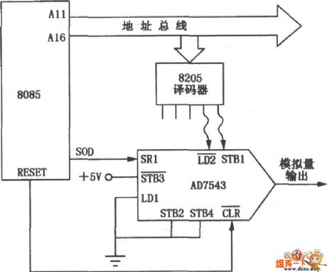
Long distance transmission interface circuit (AD7543)
Published:2011/5/26 2:13:00 Author:Christina | Keyword: Long distance, transmission, interface circuit
View full Circuit Diagram | Comments | Reading(552)
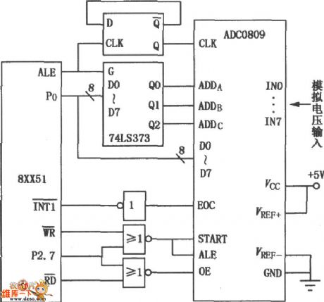
SCM interface circuit (ADC0809)
Published:2011/5/26 2:14:00 Author:Christina | Keyword: SCM, interface circuit
View full Circuit Diagram | Comments | Reading(536)
Long tail type differential amplifier circuit
Published:2011/5/25 21:50:00 Author:Christina | Keyword: Long tail, differential amplifier
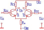
As the right figure shows, the differential-mode gain is 48dB, the common mode rejection ratio is 67dB,Ui1=5V,Ui2=5.01V, try to know the output voltage Vo.
(View)
View full Circuit Diagram | Comments | Reading(566)
Simple voltage control oscillator circuit
Published:2011/5/25 19:16:00 Author:Christina | Keyword: Simple, voltage control, oscillator
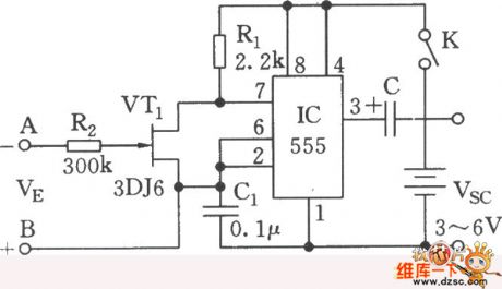
As the figure shows, the circuit uses the 555 and the MOSFET 3DJ6 as the core to form the controllable multivibrator. When you add the control voltage VK to the A and B ends, the 3DJ6's equivalent resistance RDS between the drain port and the source port will change, so the oscillation frequency of 555 changes too. And this circuit can be used in the applications of V/F conversion and tone recognition. (View)
View full Circuit Diagram | Comments | Reading(985)
2X12W integrated amplifier TDA1521 application circuit
Published:2011/5/25 19:06:00 Author:Christina | Keyword: 2X12W, integrated amplifier, application circuit
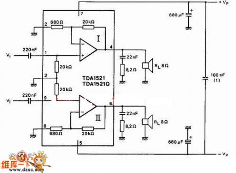
Figure: 2X12W integrated amplifier TDA1521 application circuit
(View)
View full Circuit Diagram | Comments | Reading(1258)
TDA1521 practical making miniature amplifier circuit
Published:2011/5/25 19:10:00 Author:Christina | Keyword: practical making, miniature, amplifier
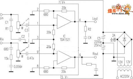
Figure: TDA1521 practical making miniature amplifier circuit
(View)
View full Circuit Diagram | Comments | Reading(1431)
The oscillator circuit with the independent adjustable charging and discharging time
Published:2011/5/25 19:03:00 Author:Christina | Keyword: oscillator, circuit, independent adjustable, charging, discharging, time
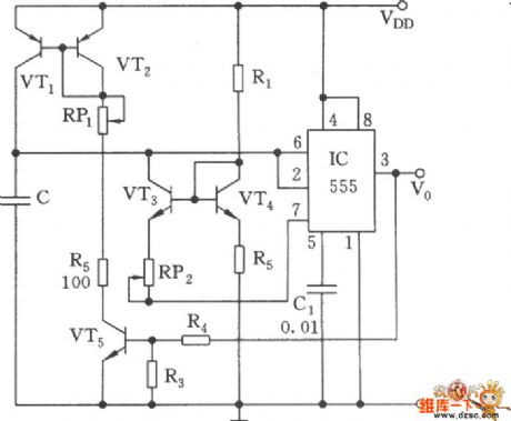
As the figure shows, the adjustment of common 555 multivibrator's charging and discharging time will influence each other. This circuit uses the mirror current source mode to keep the independence of the capacitance C's charging loop and discharging loop, and this circuit ensures the linearity of the charging and discharging. At the beginning, the output is the high level, VT5, VT2 and VT1 conduct, C is charged by VT1's constant-current, when VT1 has the 2/3VDD threshold level, 555 sets, pin-3 has the low level, and VT5 cuts off. C is discharged by the VT3 and IC's discharging tube, when the voltage of C is 1/3VDD, 555 sets. This cycle goes round and round to form the oscillation. (View)
View full Circuit Diagram | Comments | Reading(617)
1m laser length measuring machine stripe counter preamplifier circuit
Published:2011/5/30 3:37:00 Author:Christina | Keyword: 1m, laser, length, measuring, stripe counter, preamplifier
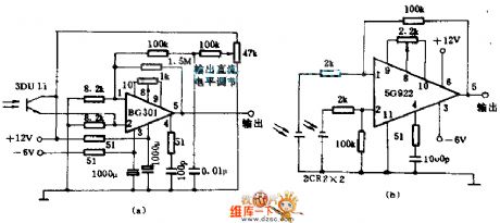
The figure a shows the circuit with the 200 amplification factor, the bandwidth is 0 to 100KHZ, and it can be used in the preamplification of the 1m laser length measuring machine stripe counter.
The figure b shows the circuit with the 50 amplification factor, the bandwidth is 0~200KHZ, the phase difference of the two photocells output signal is 180°, and it is amplified by the 5G922. This circuit can be used in the preamplification of the grating moore stripe subdivision circuit.
(View)
View full Circuit Diagram | Comments | Reading(1268)
ocl power amplifier circuit
Published:2011/5/30 3:29:00 Author:Christina | Keyword: ocl, power amplifier
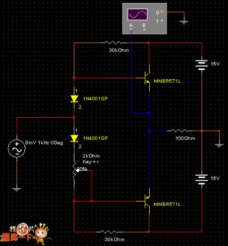
Figure: ocl power amplifier circuit
(View)
View full Circuit Diagram | Comments | Reading(1083)
Antenna booster circuit with the mix-amplification mode
Published:2011/5/30 2:31:00 Author:Christina | Keyword: Antenna, booster, mix-amplification
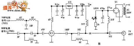
The antenna booster circuit with the mix-amplification mode is as shown. The working principle is the same as the amplification-mix mode.
Figure: Antenna booster circuit with the mix-amplification mode (View)
View full Circuit Diagram | Comments | Reading(1340)
multistage amplifier circuit
Published:2011/5/30 2:16:00 Author:Christina | Keyword: multistage, amplifier circuit
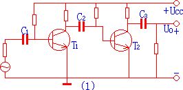
1. Coupling modes of the multistage amplifier circuit
In practice we always use three kinds of coupling modes: the resistance capacitance coupling, the direct coupling and the transformer coupling.
(1). Resistance capacitance coupling
It's connection method: connect the preamplifier output to the rear-amplifier output through the resistance and the capacitance.
It's features: the quiescent operating points of the stages are independent and easy to adjust.
It's weak point: can not amplify and change the slow signal and do not easy to integrate. The figure 1 shows the resistance capacitance coupling connection.
(2). Direct coupling
In order to avoid the influence of the capacitance to the slowly changing signal, we connect the two stages of amplifier circuits together, this is the direct coupling.
It's features: it can amplify the AC signal and the DC signal, easy to integrate, but it has the zero drift phenomenon.
Figure: multistage amplifier circuit (View)
View full Circuit Diagram | Comments | Reading(1422)
Instrument Amplifier (INA101) Circuit With Eliminating AC Noise
Published:2011/5/19 8:10:00 Author:Robert | Keyword: Instrument Amplifier, Eliminating, AC, Noise
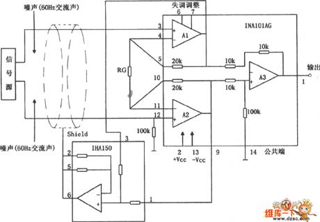
The instrument amplifier (INA101) circuit with eliminating AC noise is shown in the picture below. The amplification stage A1, A2 in the picture are chosen to use the integrated amplifier INA101, and the back stage A3 is chosen to use INA105. Also it uses the INA105 to make up the circuit like the feedbacl connection. So this would limit the power's AC noise.
(View)
View full Circuit Diagram | Comments | Reading(760)
INA166 Low-Noise Low-Distortion Instrument Amplifier Pin Circuit
Published:2011/5/21 21:22:00 Author:Robert | Keyword: Low-Noise, Low-Distortion, Instrument, Amplifier, Pin
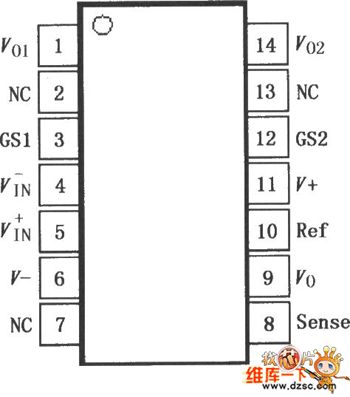
The INA166 is a low-noise, low-distortion instrument amplifier. The design of current feedback circuit makes it have a wide bandwidth and excellent dynamic response in a wide gain rang. The INA166 can be used in amplification of weak signals, such as miniature microphone (mike) and the amplification of underwater sound measurement device.Many industrial, instrument and medical applications also profit from its low noise and wide bandwidth. And its special distortion elimination circuit can reduce the distortion to very low level. With 200Ω source resistance the INA166 provides the low-noise performance which is almost close to the theoretical value.
(View)
View full Circuit Diagram | Comments | Reading(554)
input protection with optoelectronic isolator circuit
Published:2011/5/29 7:11:00 Author:chopper | Keyword: optoelectronic isolator, input protection
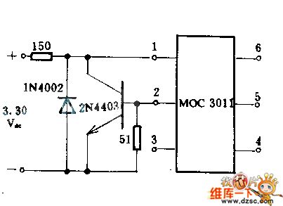
This circuit combines diode and transistor together.When the input voltage is between 3 and 30V,the incoming current of LED of the optoelectronic isolator MOC3011 is limited to a secure ultimate value that is less than 15mA.If the polarity is set reversely by accident,this circuit can also protect the LED.
(View)
View full Circuit Diagram | Comments | Reading(730)
| Pages:215/250 At 20201202203204205206207208209210211212213214215216217218219220Under 20 |
Circuit Categories
power supply circuit
Amplifier Circuit
Basic Circuit
LED and Light Circuit
Sensor Circuit
Signal Processing
Electrical Equipment Circuit
Control Circuit
Remote Control Circuit
A/D-D/A Converter Circuit
Audio Circuit
Measuring and Test Circuit
Communication Circuit
Computer-Related Circuit
555 Circuit
Automotive Circuit
Repairing Circuit