
Amplifier Circuit
Index 214
BA3416BL-the integrated dual preamplifier circuit
Published:2011/5/15 4:51:00 Author:Borg | Keyword: integrated, preamplifier circuit
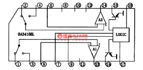
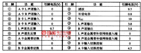
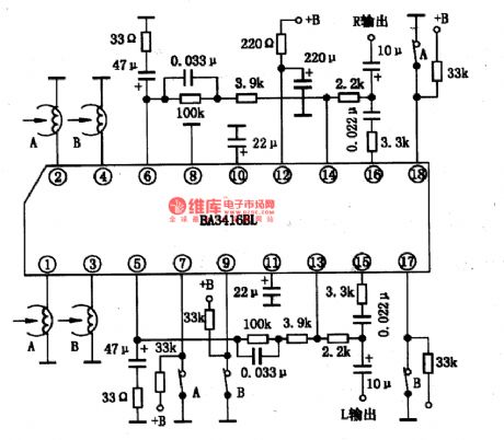
BA3416BL is an integrated dual preamplifier circuit produced by Toyo Power Tool Corp., Japan, which is used in recorders and music centers.1.the internal circuit and pin functions of BA3416BLBA3416BL contains two lines of pre-amplifiers and logic controllers. Logic control circuit is to shift double-track head signal and shift the selecting circuit of metal straps and common straps.The internal circuit of BA3416BL is as shown in Figure 1. The IC is in 18-lead unilateral dual in-line package, whose pin functions and data are listed in Figure 1.
(View)
View full Circuit Diagram | Comments | Reading(3164)
BA3520-the integrated reproducing circuit of single door stereo
Published:2011/5/14 21:33:00 Author:Borg | Keyword: reproducing circuit, single door
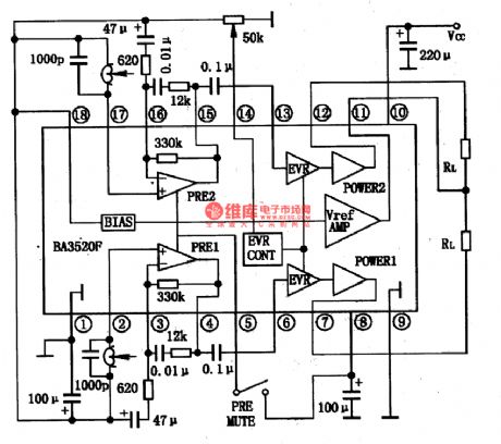
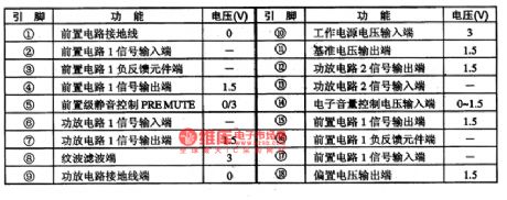
BA3520 is an integrated reproducing circuit of low-voltage single door stereo reproducing produced by Toyo Corp., Japan, which is widely used in low-voltage walk-man and other low-voltage radios.the internal circuit and pin functions of BA3520BA3520 contains sub-circuits of dual head, dual power amplifier and power volume control, whose internal circuit and typical application circuit are listed in Figure 1. It is in flat 18-lead dual line package, whose pin functions and data are listed in Table 1.
Figure 1 the internal circuit and typical application circuit of BA3520F
(View)
View full Circuit Diagram | Comments | Reading(1122)
BA3506A-the integrated reproducing circuit of single door stereo
Published:2011/5/15 1:07:00 Author:Borg | Keyword: integrated reproducing circuit, single door
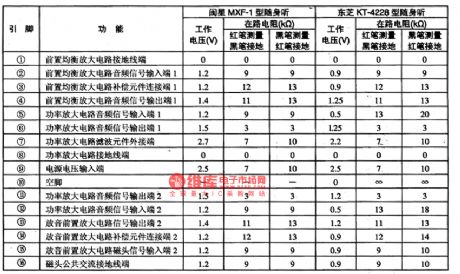
BA3506A is an integrated reproducing circuit of single door stereo produced by Toyo Power Tool Corp., Japan, which is used in walk-man and stereos of same type as reproducing circuit.1.the internal circuit and pin functions of BA3506ABA3506A consists of two preset balance amplifier circuits of same functions and power amplifier circuits, whose internal circuit is shown in Figure 1. The IC is in 16-lead dual in-line plastic package, whose pin functions and data are listed in Table 1.2.main parameters of BA3506A
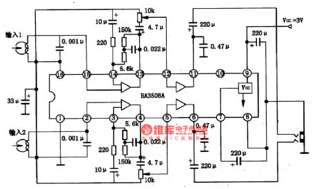
3.Typical application circuit of BA3506A
(View)
View full Circuit Diagram | Comments | Reading(1166)
Digital control type astable multivibrator circuit
Published:2011/5/25 20:16:00 Author:Christina | Keyword: Digital control, astable multivibrator
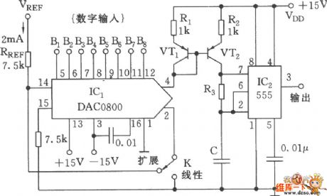
As the figure shows, the oscillator is composed of the DAC, the mirror current source and the 555 oscillator. The oscillation frequency is related to the input data size and the control reference voltage. IC1 uses the D/A conversion circuit DAC0800 LCN, this circuit is the 8-bit DAC, it changes the data into the analog signal and adds the signal to the mirror current source VT1's b port, so it controls the VT2's integrated electrode current - 555 oscillator C's charging current, and also changes the frequency of the oscillator. (View)
View full Circuit Diagram | Comments | Reading(1610)
DS8922 differential line driver and receiver circuit
Published:2011/5/25 21:27:00 Author:Christina | Keyword: differential line, driver, receiver
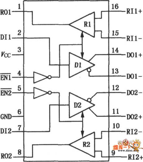
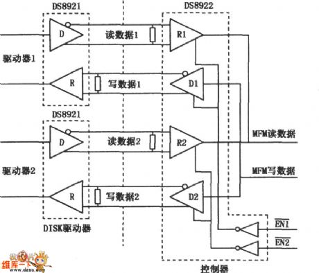
The DS8922 meets the requirement of EIA standard RS-422, the output delay time is 0.5ns; the propagation delay time ≤12ns; it uses the high differential or common-mode input mode; the voltage range is ±7V; the voltage is output by the complementary driver; it can be used to non-polarity differentially drive the twisted-pair lines or the parallel transmission lines; the complementary output is the logic. The DS8922 can be used in the occasions which are meet the ST506, ST412 and ESDI wheel drive standards, and it is compatible with the CMOS circuit.
The internal circuit block diagram of the DS8922:
The typical application circuit:
(View)
View full Circuit Diagram | Comments | Reading(1191)
Differential mode signal and differential mode voltage amplification factor Aud circuit
Published:2011/5/26 1:00:00 Author:Christina | Keyword: Differential, mode signal, mode voltage, amplification factor, Aud
Differential mode signal--Add the same amplitude opposite polarity signals on the differential amplification tube T1 and T2's base electrode. As the figure shows:
The function of the differential mode signal: because the signals' polarities are opposite, so T1's collector electrode voltage reduces, T2's collector electrode voltage increases, and the variable quantitiy absolute values of T1 and T2 are the same, so Uod=Uc1=Uc2=2Uc1 (or 2Uc2) (View)
View full Circuit Diagram | Comments | Reading(478)
PCA8581 I2C port 128×8-bit E2PROM circuit
Published:2011/5/26 1:24:00 Author:Christina | Keyword: I2C port, 128×8-bit, E2PROM
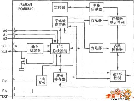
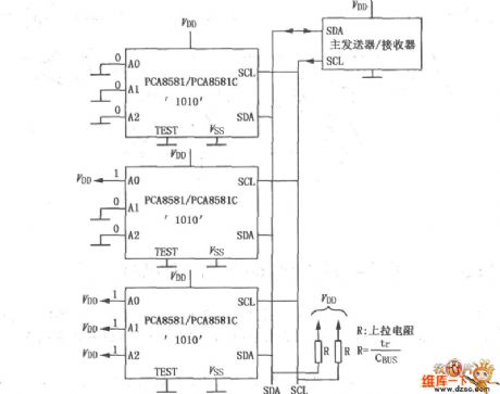
The PCA8581 has the 128×8-bit E2PROM address; the data can be transmitted by two bidirectional buses (the I2C) through the serial port; it has three address pins A0, A1, A2, the function is to ensure the hardware address; also it can directly drive eight devices to the bus but needs no additional accessories, it can be used in the applications which are related to the industrial computer storage control projects.
Internal circuit blockdiagram:
Typical application circuit:
(View)
View full Circuit Diagram | Comments | Reading(645)
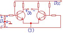
Common-mode signal and common-mode voltage magnifacation Auc circuit
Published:2011/5/26 1:55:00 Author:Christina | Keyword: Common-mode signal, common-mode voltage, magnifacation , Auc
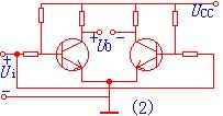
The Common-mode signal--Adds the same amplitude opposite polarity signals on the differential amplification tube T1 and T2's base electrode. As the figure shows:
The function of the common-mode signal: it has the synclastic effects to the two tubes, it will cause the commensuration increase of the current and the commensuration reducing of the collector potential, so the two tube's collector electrode output common-mode voltage Uoc is zero. (View)
View full Circuit Diagram | Comments | Reading(546)
Mixed mode antenna amplifier circuit
Published:2011/5/30 2:47:00 Author:Christina | Keyword: Mixed mode, antenna amplifier
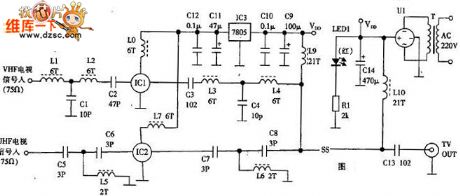
The amplification-mix mode antenna amplifier circuit is as shown in figure 1. The 1 to 12 channels TV signal is input from the VHF input port, the simple low-pass filter is composed of the L1, C1 and L2, the TV signal (filtered the channel 12) is delivered to the IC1 signal input port to accept the 20dB amplification, then the amplified TV signal is output through the capacitance C3, at last it is mixed with the UHF signal by the L3, C4, L4 low-pass filters, then it is delivered to the TV signal output port.
Figure: Mixed mode antenna amplifier circuit
The simple high-pass filter is composed of the C5, L5 and C6, it only allows the 13 channel and the raer channels of UHF band to get through. (View)
View full Circuit Diagram | Comments | Reading(1049)
Xunda MB-DS elevator cooling fan circuit
Published:2011/6/2 1:33:00 Author:TaoXi | Keyword: Xunda, elevator, cooling fan
Xunda MB-DS elevator cooling fan circuit (View)
View full Circuit Diagram | Comments | Reading(507)
AC/DC darkroom safelight circuit
Published:2011/5/26 21:13:00 Author:Christina | Keyword: AC, DC, darkroom, safelight
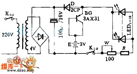
This circuit has the function of non-contactor auto-convert switch, and it uses the orange color LED.
When the power supply is normal, the rectifying power supply supplies power to the LED; when the power is failure, the battery E supplies power to LED through BG. Once the city electricity recovers, BG automaticly cuts off.
(View)
View full Circuit Diagram | Comments | Reading(1128)
The circuit diagram of preamplifier made by MC1709 serves the electric motor drive
Published:2011/6/1 22:33:00 Author:leo | Keyword: The circuit diagram of preamplifier made by MC1709 serves the electric motor drive, MC1709
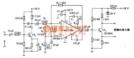
What Picture 1 shows is a kind of preamplifier made by MC1709 serves the electric motor drive circuit. In this circuit, the voltage plus of symbolic amplifier circuit is 39 dB. The circuit is made up of MC1709 and so on. The bandwidth of amplifier is 41 KHz which is decided by R5 and C2.Its single-ended output passes through the phase position of VT2 and is divided into two signals with discrepancy of 180 degree angle. This process will drive sh-pull (PP) output amplifier.
(View)
View full Circuit Diagram | Comments | Reading(1988)
The circuit diagram of preamplifier made by MC1437 serves the electric motor drive
Published:2011/6/1 22:36:00 Author:leo | Keyword: The circuit diagram of preamplifier made by MC1437 serves the electric motor drive, MC1437
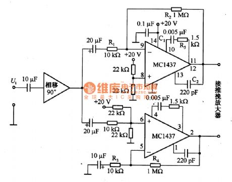
What Picture 1 shows is a kind of preamplifier made by MC1437 serves the electric motor drive circuit. In this circuit, the voltage plus of symbolic amplifier circuit is 39 dB. The circuit is made up of MC1709 and so on. The bandwidth of amplifier is 41KHz which is decided by R5 and C2.Its single-ended output passes through the phase position of VT2 and is divided into two signals with discrepancy of 180 degree angle. This process will drive sh-pull (PP) output amplifier. (View)
View full Circuit Diagram | Comments | Reading(987)
the circuit of tv signal switching amplified principle
Published:2011/6/1 9:20:00 Author:Ariel Wang | Keyword: tv, signal, switching amplified, principle
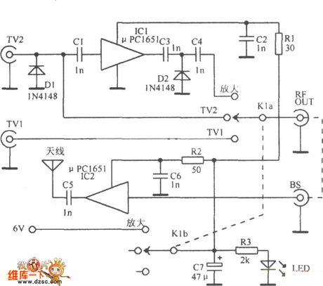
The circuit of tv signal switching amplified principle can be seen as the chart.
(View)
View full Circuit Diagram | Comments | Reading(589)
the amplified circuit of an improved Durestos All-Channel Antenna
Published:2011/6/1 9:25:00 Author:Ariel Wang | Keyword: amplified, improved, Durestos, All-Channel , Antenna
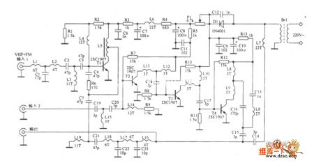
The amplified circuit of an improved Durestos All-Channel Antenna can be seen as the chart.
(View)
View full Circuit Diagram | Comments | Reading(670)
800W three-port two-way SCR light-reducing circuit
Published:2011/5/29 8:42:00 Author:Christina | Keyword: 800W, three-port, two-way, SCR, light-reducing
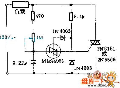
The MBS4991 two-way SCR switch is produced by the Motorola company, you can control the three-port two-way SCR by using it. The 1MΩ resistance can change the three-port two-way SCR's angle of flow from 0°to 170°. When the angle of flow is maximum, the power that adds to the load can be more than 97% of the full power. No matter which position the tone potentiometer is, the first half cycle's angle of flow is the same as the rear half cycle's.
(View)
View full Circuit Diagram | Comments | Reading(997)
TDA1521 single power supply supplying application circuit
Published:2011/5/25 19:05:00 Author:Christina | Keyword: single power supply, supplying, application circuit
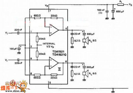
Figure: TDA1521 single power supply supplying application circuit
(View)
View full Circuit Diagram | Comments | Reading(747)
Limit reminding spiral circuit composed of sixty LEDs
Published:2011/5/20 2:18:00 Author:Christina | Keyword: Limit reminding, spiral circuit, sixty LEDs
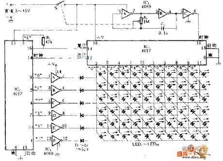
The sixty LEDs are arranged in spiral form on the display board; the connecting line connects to two 4017 ICs with the matrix form. So when the IC2 and IC1 count respectively, every light emitting diode turns on as the permutation order. The IC3 is the square wave oscillator, the frequency depends on the R2 and C1's values, the output of it is used as the IC1's clock, when IC1's count is 10, it will output a carry output as the IC2's clock. When the count is 60, IC1 and IC2 are all reset to zero, the new cycle starts. Both two integrated circuits have the limited flow function.
(View)
View full Circuit Diagram | Comments | Reading(2881)
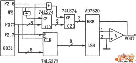
AD7520 "burr" phenomenon overcoming interface circuit
Published:2011/5/26 7:51:00 Author:Christina | Keyword: "burr" phenomenon, overcoming, interface circuit
View full Circuit Diagram | Comments | Reading(719)
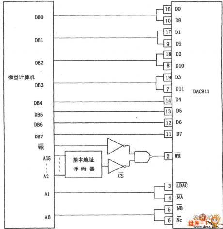
DAC811 right aligned data format address searching circuit connection diagram
Published:2011/5/26 8:11:00 Author:Christina | Keyword: right aligned, data format, address, searching, connection diagram
View full Circuit Diagram | Comments | Reading(724)
| Pages:214/250 At 20201202203204205206207208209210211212213214215216217218219220Under 20 |
Circuit Categories
power supply circuit
Amplifier Circuit
Basic Circuit
LED and Light Circuit
Sensor Circuit
Signal Processing
Electrical Equipment Circuit
Control Circuit
Remote Control Circuit
A/D-D/A Converter Circuit
Audio Circuit
Measuring and Test Circuit
Communication Circuit
Computer-Related Circuit
555 Circuit
Automotive Circuit
Repairing Circuit