
Basic Circuit
Index 405
KA2304 (toy)wireless remote control receiving control regulation circuit
Published:2011/6/1 9:39:00 Author:Lena | Keyword: wireless, remote control, receiving, regulation
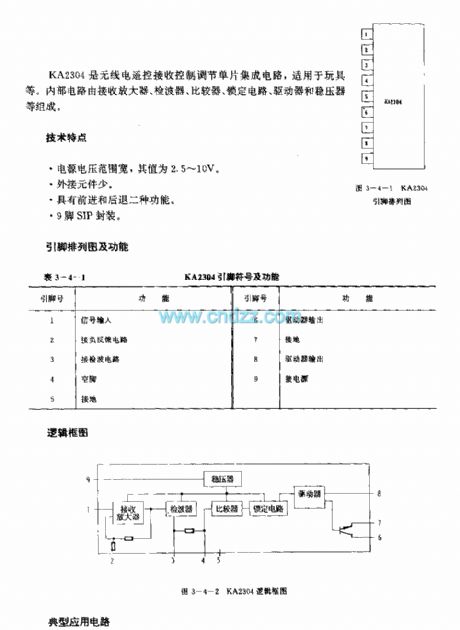
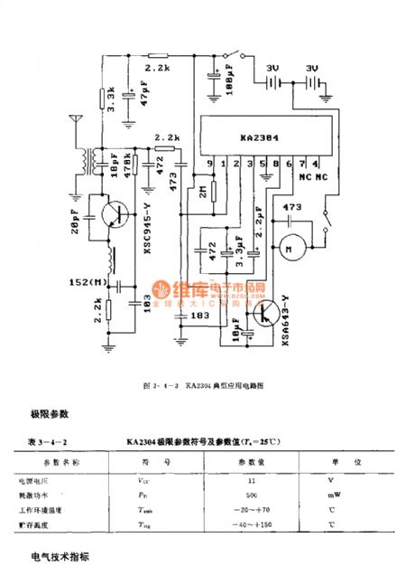
KA2304 is a wireless remote control receiving control regulation single integrated circuit which is applied to toys etc. Internal circuit consists of receiving amplifier, detector, comparator, lock circuit, driver and voltage regulator etc.
Technical characteristicWide power supply range, the value is 2.5~10V.Few external elementsThe circuit has two functions, go ahead and fall back.9-pin SIP package
(View)
View full Circuit Diagram | Comments | Reading(713)
KA2303 (toy)wireless remote control receiving control regulation circuit
Published:2011/6/1 9:40:00 Author:Lena | Keyword: wireless, remote control, receiving, regulation
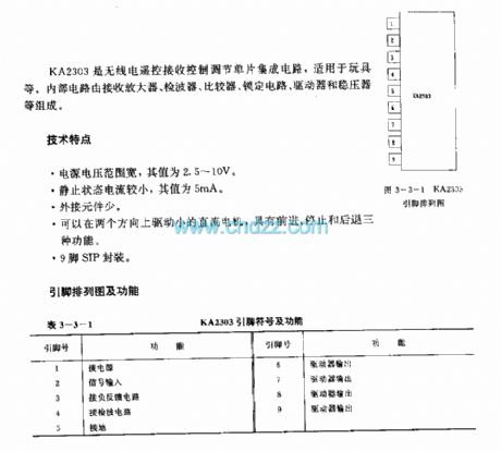
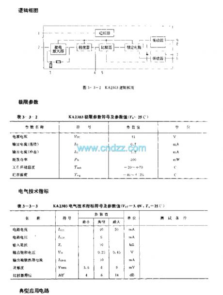
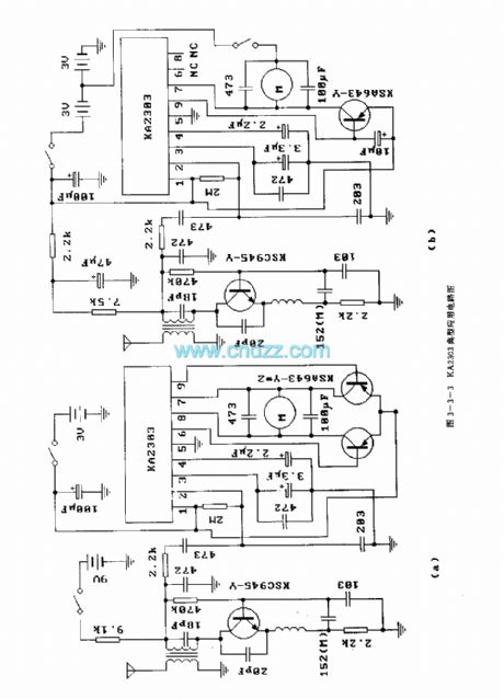
KA2303 is a wireless remote control receiving control regulation single integrated circuit applied to toys etc. Internal circuit consists of receiving amplifier, detector, comparator, lock circuit, driver and voltage regulator etc.
Technical characteristicWide power supply range, the value is 2.5~10V.The current is small when at rest, the typical value is 5mAFew external elementsThe circuit can drive little direct-current generator and has three functions, go ahead, stop and fall back.9-pin SIP package
(View)
View full Circuit Diagram | Comments | Reading(1305)
Water level indicator circuit (3)
Published:2011/5/29 9:01:00 Author:Christina | Keyword: Water level, indicator
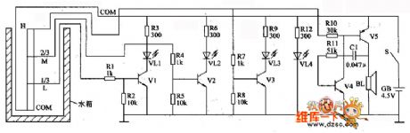
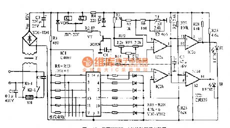
The water level indicator circuit is composed of the three-stage water level indicator circuit and the audio oscillator, as the figure shows.
The three stages water level indicator circuit is composed of the water-level sensor, the transistors Vl-V3, the light-emitting diodes Rl-R9. The low water level (1/3 water level) display circuit is composed of the VLl and Vl, Rl, R3; the 2/3 water level display circuit is composed of the VL2, R4-R6, V2; the high water level display circuit is composed of the VL3 and R7-R9, V3.
The audio oscillator is composed of the transistors V4 and V5, the resistors RlO and RII, the capacitor C.
The VL4 is the power indicator light emitting diode; the BL is the fuu-water alarm speaker.
When the water level of the water tank is lower than the low water level electrode L, the Vl-V3 cut off, the VLl-VL3 turn off. (View)
View full Circuit Diagram | Comments | Reading(1983)
LED zero beat display circuit
Published:2011/5/19 20:07:00 Author:Christina | Keyword: LED, zero beat, display circuit
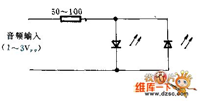
The two LEDs are connected with the opposite polarity, by the precision tuning of the receiver, the beat frequency can be displayed easily and intuitively. If the deviation of the beat frequency is above 1KHZ, the two LEDs are both blinking; if the deviation of the beat frequency is less than ±5HZ, the LED turns off. The luminous intensity of light emitting diode is decided by the audio amplifier low frequency response.
(View)
View full Circuit Diagram | Comments | Reading(1016)
Internal Circuit Block Diagram of LN8363D/DH Integrated Circuit
Published:2011/6/9 3:49:00 Author:Vicky | Keyword: LN8363D/DH Integrated Circuit,
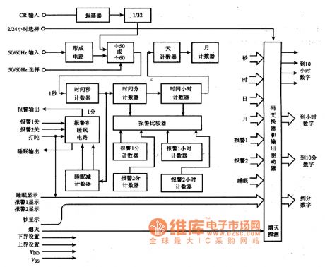
Functions and Characteristics
The interior of LM8363D/DH integrated circuit is mainly composed of blanking circuit, frequency-dividing circuit and various counters and so on. LM8363D/DH integrated circuit has two warning systems and can display month, date (can be read by the pressing the key of “nap input”) and time. LM8363D/DH integrated circuit can preset sleep timer of 59min. The internal circuit block diagram of LM8363D/DH integrated circuit is as shown in the picture. (View)
View full Circuit Diagram | Comments | Reading(927)
Typical Applied Circuit Diagram of LM1876 Integrated Circuit
Published:2011/6/9 4:14:00 Author:Vicky | Keyword: LM1876 Integrated Circuit, LM1876
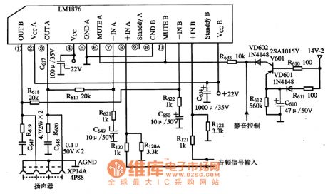
LM1876 integrated circuit has three working mode: stand-by, squelch, and running. The current dissipation of stand-by is just 4.2mA. The power can be supplied by both positive and negative power. The typical applied circuit is as shown in the picture.
Internal circuit of LM1876 integrated circuit mainly include low-voltage protection circuit, over-power protection circuit, over-heat protection circuit, two power preamp circuits of the same function, two squelch control circuits of the same function , two stand-by control circuits of the same function , and power supply processing circuit of the same circuit and so on. (View)
View full Circuit Diagram | Comments | Reading(4523)
SAA1064--the dynamic drive connector diagram of serial I2C general LED display drive integrated circuit
Published:2011/6/10 0:38:00 Author:qqtang | Keyword: dynamic drive, general LED display, integrated circuit
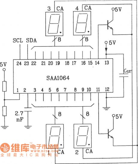
As SAA1064 dynamic scanning display depends on the multi-way switch data lock that controls circuit in time, so the main devices needn't get in, therefore, it's the most general way to perform the potential of SAA1064. In the figure, the position No. of LED is responding to the section data sequence in the data operation mode. CEXT is the clock oscillating capacitor, which makes sure the working signal of dynamic drive is normal. MX1 and MX2 are the output terminals of the displayer public pole drive signal. The timing wave outlines of MX1 and MX2, which are in the dynamic scanning state, are shown in Figure1.
(View)
View full Circuit Diagram | Comments | Reading(2772)
Typical Applied Circuit Diagram of LM386N Integrated Circuit
Published:2011/6/9 4:27:00 Author:Vicky | Keyword: LM386N Integrated Circuit,
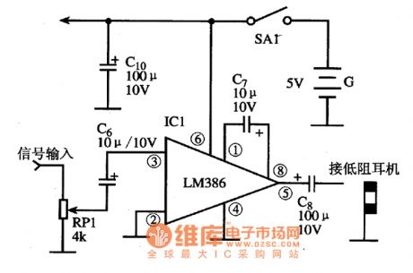
Typical Applied CircuitThe typical applied circuit of power amplifier circuit which is composed of LM386 integrated circuit is shown in the following picture.
Hint: LM386N without suffix is a general type, the difference of different suffix only lies in the electrical parameter and package.
The limit parameter of LM386N一l: power supply voltage is 15V, and enable power dissipation is 0.66W
The limit parameter of LM386N一4: power supply voltage is 22V, and enable power dissipation is 1.25W
The limit parameter of LM386N一2 and LM386-3 is between the aboved two integrated
circuit. (View)
View full Circuit Diagram | Comments | Reading(1538)
CXD750096-013Q- the integrated microcomputer circuit of system control
Published:2011/5/14 21:17:00 Author:Borg | Keyword: integrated microcomputer circuit, system control
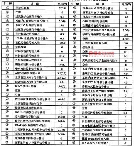
1.function featuresCXD750096-013Q contains IC trunk control circuits, key switching encoding circuits, main synchronous signal processing circuits of 100Hz, main/vice tuner AFT signal processing circuits, OSD display circuits,main synchronous signal processing circuits of 50Hz, indicator drive control circuits, audio protection test circuits and silence-noise control circuits, etc.2.pin functions and dataCXD750096-013Q is in flat 64-lead package, whose pin functions and data are listed in Table 1-1.Table 1-1 pin functions and data of CXD750096-013Q
(View)
View full Circuit Diagram | Comments | Reading(2682)
The electric thermos circuit (01)
Published:2011/6/3 0:13:00 Author:Seven | Keyword: electric thermos
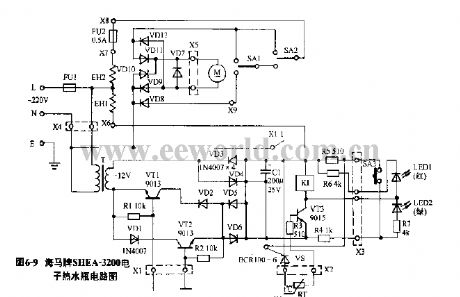
Figure 6-9 the Haima SHEA-3200 electric thermos circuit (View)
View full Circuit Diagram | Comments | Reading(1223)
The electric thermos circuit (02)
Published:2011/6/3 0:11:00 Author:Seven | Keyword: electric thermos
View full Circuit Diagram | Comments | Reading(833)
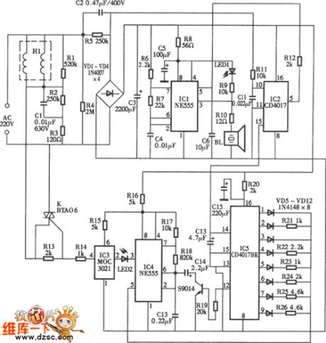
electronic mouse trap circuit
Published:2011/6/8 7:28:00 Author:chopper | Keyword: electronic, mouse trap
View full Circuit Diagram | Comments | Reading(5697)
Internal Circuit Diagram of LM2931 Integrated Circuit
Published:2011/6/9 3:54:00 Author:Vicky | Keyword: LM2931 Integrated Circuit,
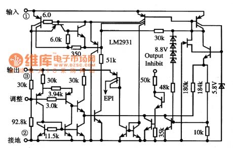
Functions and Characteristics
The Interior of LM2931 Integrated Circuit is mainly made of over-current protection circuit, over-voltage protection circuit and over-heat protection circuit, and it has the function of automatically stopping output when the power supply is reversed. The internal circuit diagram of LM2931 integrated circuit is as shown in the picture. (View)
View full Circuit Diagram | Comments | Reading(1092)
BA6104--the 5 bit LED potentiometer drive integrated basic application circuit
Published:2011/6/9 22:23:00 Author:qqtang | Keyword: potentiometer drive, basic application circuit
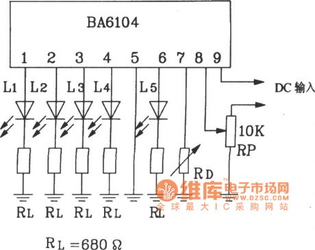
BA6104--the 5 bit LED potentiometer drive integrated basic application circuitAs the BA6104 input stage is in the PNP compound transistor basic pole input way, so its input impedance is very high. The output stage is emitter follower, so by adjusting the LED external resistor RL in the figure, the LED drive circuit can be changed. The external resistor, which is connected with 7-pin, can change Vref, when 7-pin is released, the Vref is controlled by IC, and its value is close to 1V. If the LED display LEV is required to be lower than 1v, we just link a resistor RD between 7-pin and the ground, then the Vref is reduced, see as the figure. (View)
View full Circuit Diagram | Comments | Reading(1212)
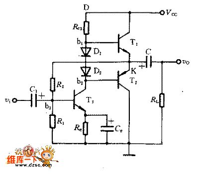
class AB dual-supply complementary symmetry circuit
Published:2011/6/8 20:06:00 Author:chopper | Keyword: class AB, dual-supply, complementary symmetry
View full Circuit Diagram | Comments | Reading(640)
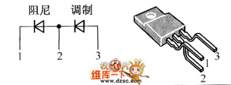
crystal diode DMV1500HFD5 internal circuit
Published:2011/6/8 20:09:00 Author:chopper | Keyword: crystal diode, internal

View full Circuit Diagram | Comments | Reading(505)
crystal diode DMV1500HFD internal circuit
Published:2011/6/8 20:11:00 Author:chopper | Keyword: crystal diode, internal
View full Circuit Diagram | Comments | Reading(549)
BZN-5 electronic fly trap circuit
Published:2011/6/8 7:51:00 Author:chopper | Keyword: electronic, fly trap

View full Circuit Diagram | Comments | Reading(1901)
7W electronic repellent circuit
Published:2011/6/8 7:41:00 Author:chopper | Keyword: 7W, electronic repellent
View full Circuit Diagram | Comments | Reading(827)
Typicall Applied Circuit Diagram of LM8560 Integrated Circuit
Published:2011/6/9 3:42:00 Author:Vicky | Keyword: LM8560 Integrated Circuit, LM8560
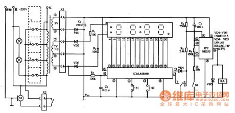
Picture: Typical Applied Circuit of LM8560 Integrated Circuit (View)
View full Circuit Diagram | Comments | Reading(7265)
| Pages:405/471 At 20401402403404405406407408409410411412413414415416417418419420Under 20 |
Circuit Categories
power supply circuit
Amplifier Circuit
Basic Circuit
LED and Light Circuit
Sensor Circuit
Signal Processing
Electrical Equipment Circuit
Control Circuit
Remote Control Circuit
A/D-D/A Converter Circuit
Audio Circuit
Measuring and Test Circuit
Communication Circuit
Computer-Related Circuit
555 Circuit
Automotive Circuit
Repairing Circuit