
Basic Circuit
Index 417
Electronic stethoscope(2)
Published:2011/5/10 21:07:00 Author:Nicole | Keyword: electronic stethoscope
This electronic stethoscope has the feature of clear sound, it can replace the ordinary stethoscope without amplification function.
The working principle of this circuit
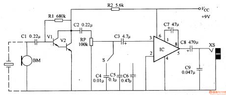
This electronic stethoscope circuit is composed of microphone preamplifier, tone control, volume control and power amplifier circuit, it is shown in the figure 9-137.
The preamplifier circuit is made of transistors Vl、V2 and capacitors Cl、C2, resistors Rl、R2.
RP is volume potentiometer.
The tone control circuit is composed of selection switch S and capacitors C4-C6.
The power amplifier circuit consists of integrated circuit IC and capacitors C3, C7-C9.
The microphone BM is fixed to the probe of stethoscope, it can change the sound singal such as body heart, lung, pulse into electrical signal, it is coupled to V1's base by C1, after passing V1, V2 preamplifiers and tone, volume control, it is imported from 3-foot of power amplifier IC. The audio singal is exported from 5-foot by IC amiplifier, then it is coupled to earphone socket XS by C8, at last, it restores the amplified sound by external earphone.
(View)
View full Circuit Diagram | Comments | Reading(5740)
Electronic stethoscope(1)
Published:2011/5/10 20:38:00 Author:Nicole | Keyword: electronic stethoscope
The traditional medical stethoscope has no amplification, weak voice, it's uncomfortable when wedge it in ears, it is affected by environmental noise easily. This electronic stethoscope adopts multi-stage low noise amplifier, the output volume is adjustable, the frequency respondse has good effect, the background noise is low, it also LED display function.
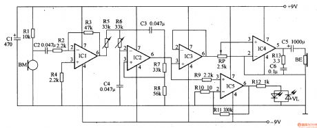
This electronic stethoscope circuit is composed of pickup sensor, preamplifier, low-pass filter amplifier, buffer, audio amplifier, LED display circuit, it is shown in the figure 9-136.
The pickup sensor circuit is composed of microphone BM and R1.
The preamplifier is composed of integrated operational amplifier circuit and resistors R2-R5.
The low-pass filter amplifier is composed of operational amplifier integrated circuit IC2 and transistors R6-R8, capacitors C3, C4, the cut-off frequency is slightly larger than 100Hz.
The buffer amplifier is composed of integrated operational amplifier circuit IC3.
The audio amplifier consists of volume potentiometer RP, low voltage audio amplifier integrated circuit IC4, resistor R13, capacitors C5, C6.
(View)
View full Circuit Diagram | Comments | Reading(6299)
Direct reading type hygrometer circuit
Published:2011/5/11 0:01:00 Author:Fiona | Keyword: Direct reading type, hygrometer
Illustration is direct reading type hygrometer circuit, including RH for chlorinated hammer humidity sensitive resistor. The power supply's humidity measurement bridge is made up by VT1, VT2 and T1 etc and the power supply's oscillation frequency is 250-1000Hz.Bridge output signal through the transformer T2, C3 coupled to the VT3, and the signal amplified by VT3 enters microammeter after it is bridge rectifiered by VD1-VD4, indicates the relative humidity changeslead to the current changes. By calibrating and Characterizing the humidity on the microampere dial ,it becomea simple and practical direct reading hygrometer.
var translatedXML = null;
(View)
View full Circuit Diagram | Comments | Reading(586)
CCU-FDTV-06 single chip microcomputer integrated circuit diagram
Published:2011/5/11 3:31:00 Author:Fiona | Keyword: single chip microcomputer
CCUFDTV06 is a single chip microcomputer integrated circuits.Iti (View)
View full Circuit Diagram | Comments | Reading(763)
LED digital display mode circuit diagram
Published:2011/5/12 1:42:00 Author:Ecco | Keyword: LED , digital display, mode
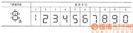
LED digital display mode is shown in Table 28-2. 7 LEDs are made in strip type, they are respectively a, b, c, d, e, f, g and on behalf of digital strokes, selected making strokes emit light, so that you can form ten 0-9 digital code. Another light-emitting diode is a decimal point DP.
The modes of LED digital display are shown as the chart.
(View)
View full Circuit Diagram | Comments | Reading(670)
TC9311F-014 logic control system IC chart
Published:2011/5/12 1:55:00 Author:Ecco | Keyword: logic control system , IC
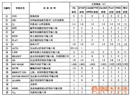
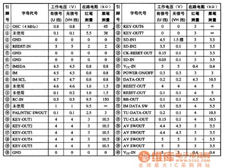
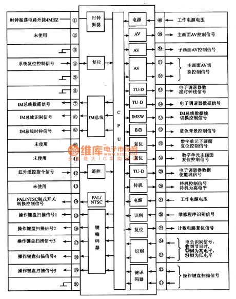
TC9311F-014 is the control system logic IC produced by Toshiba company, :It is widely applied to Ikaiwa, Toshiba and domestic walkmen and repetition machines.
TC9311F-014 IC uses a dual flat package with 20 feet, the pin functions and data are listed in Table 1. Table 1 shows TC9311F-014 IC pin functions and data.
(View)
View full Circuit Diagram | Comments | Reading(1870)
Dynamic scanning display circuit diagram
Published:2011/5/12 1:54:00 Author:Ecco | Keyword: Dynamic, scanning , display
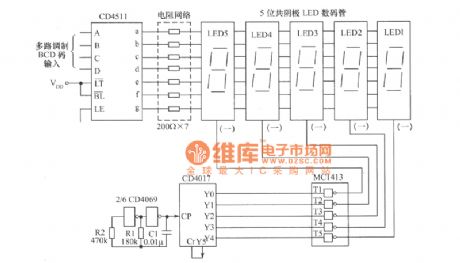
The dynamic scanning display circuit shown as the chart is composed of the decoder CD4511 and beat generator drive CD4017, 7 road Darlington drive MC1413. LED1 ~ LED5 are five common cathode LED displays.
(View)
View full Circuit Diagram | Comments | Reading(1608)
PCA8515 character formation integrated circuit diagram
Published:2011/5/12 1:45:00 Author:Ecco | Keyword: character , formation , integrated circuit
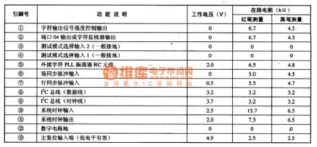
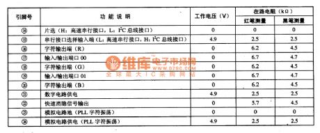
PCA8515 is the character formation integrated circuit produced by Philips, it is widely used in large screen color TV, such as Changhong color TV projection series. 1. Features of functionsPCA8515 ICcontains display with horizontal and vertical positioning pulse processing circuit, the character clock circuit, I2C bus interface circuit, reset circuit, serial interface circuit, and other auxiliary functions circuit. The block diagram of the circuit is shown as the chart. 2. Pin functions and data PCA8515 uses the hundred inserting package with 24 pin in dual rows, the pin functions and data are listed in Table.
(View)
View full Circuit Diagram | Comments | Reading(645)
10 LED level display circuit diagram
Published:2011/5/12 1:43:00 Author:Ecco | Keyword: 10, LED, level , display
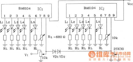
10 LED level display circuit composed of 2 pieces BA6104 5-bit LED level meter driver integrated circuit
10 LED level display circuit composed of 2 pieces BA6104 5-bit LED level meter driver integrated circuitis shown in Figure, regulating Vref of pin 7 in IC1, the L1 ~ L5 will be lit; adjusting the Vref of pin 7 in IC2 will turn on the L1 ~ IC2 L5, the light voltage is 2 times of IC1, luminous order is L1 ~ L5 in IC1, L1 ~ L5 in IC2.
(View)
View full Circuit Diagram | Comments | Reading(1771)
BL6124 5-bit LED level meter driver IC basic application circuit
Published:2011/5/12 1:43:00 Author:Ecco | Keyword: 5-bit, LED , level meter, driver , IC, basic application
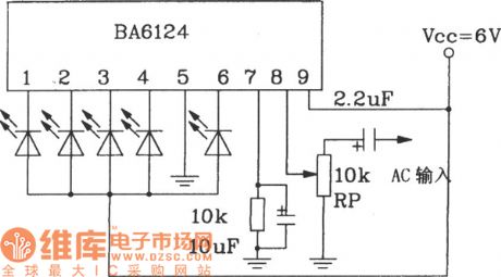
10 LED level display circuit is composed of two pieces of BA6104.LED current limiting circuit is used to limit the LED current by connecting a resistor in parallel or series next to LED, it is shown as Figure (a), (b). When working voltageis higher than 9V, it could add a shunt resistor beside the LED current end, while the circuit with different specific Vcc values are shown in Fig. (View)
View full Circuit Diagram | Comments | Reading(1750)
LED digital display internal circuit diagram
Published:2011/5/12 1:42:00 Author:Ecco | Keyword: LED, digital display , internal circuit
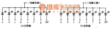
The most LEDs used in digital display are red, and they are divided into two parts of unit and sub-units. The internal circuit of unit LED digital display is shown in Figure 28-5, which is divided into common anode and cathode connection types, and they are representing the strokes of the a-g LED positive or negative ends being leaded by pins, which DP feet is on behalf of the decimal point.
LED digital display internal circuit diagram is shown as the chart. (View)
View full Circuit Diagram | Comments | Reading(644)
Pulse delay circuit circuit diagram
Published:2011/5/12 6:23:00 Author:Rebekka | Keyword: Pulse delay circuit
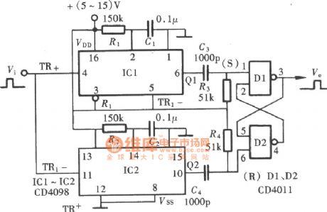
If you need to delay longer than the input pulse width of the pulse delay circuit, you can use pulse delay circuit composed of the NAND gate and single-shot. Its composition is shown in the figure. (View)
View full Circuit Diagram | Comments | Reading(2503)
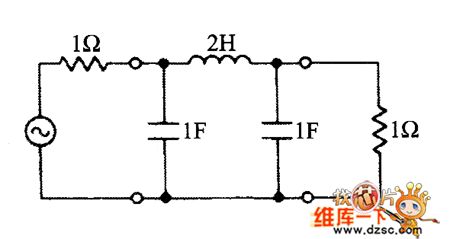
LC filter circuit diagram
Published:2011/5/12 20:44:00 Author:Nicole | Keyword: filter, LC
View full Circuit Diagram | Comments | Reading(1609)
Delay circuit with fixed-frequency coefficients
Published:2011/5/12 5:52:00 Author:Rebekka | Keyword: Delay circuit , fixed-frequency coefficients
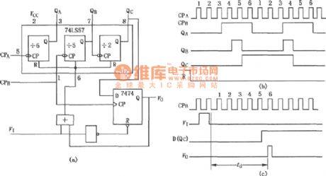
Figure is Delay circuit with fixed-frequency coefficients. The circuit is composed of the 60 divider and D flip-flop 7474. 74LS57 has a 10 frequency divider that composed of an independent 6 divider, a 5 frequency and a 2 frequency level. Its output ends are QA, QB and QC. (View)
View full Circuit Diagram | Comments | Reading(2007)
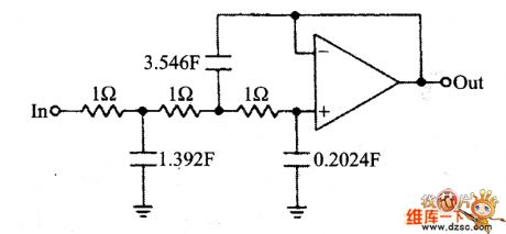
LC active filter circuit diagram
Published:2011/5/12 20:43:00 Author:Nicole | Keyword: active filter, LC
View full Circuit Diagram | Comments | Reading(1165)
Beijing Wuzhou elevator main circuit
Published:2011/5/12 20:04:00 Author:TaoXi | Keyword: Beijing, Wuzhou, elevator main circuit
Beijing Wuzhou elevator main circuit (View)
View full Circuit Diagram | Comments | Reading(437)
Beijing Chongyun elevator safety loop circuit
Published:2011/5/12 20:03:00 Author:TaoXi | Keyword: Beijing, Chongyun, elevator safety loop
Beijing Chongyun elevator safety loop circuit (View)
View full Circuit Diagram | Comments | Reading(513)
Beijing Chongyun elevator main circuit (2)
Published:2011/5/12 20:00:00 Author:TaoXi | Keyword: Beijing, Chongyun, elevator main circuit
Beijing Chongyun elevator main circuit (2) (View)
View full Circuit Diagram | Comments | Reading(391)
OTIS T0EC-CHVF elevator main circuit
Published:2011/5/12 19:55:00 Author:TaoXi | Keyword: OTIS, elevator, main circuit
OTIS T0EC-CHVF elevator main circuit (View)
View full Circuit Diagram | Comments | Reading(451)
OTIS TOEC-2000VF elevator braker circuit
Published:2011/5/12 19:52:00 Author:TaoXi | Keyword: OTIS, elevator braker
OTIS TOEC-2000VF elevator braker circuit (View)
View full Circuit Diagram | Comments | Reading(440)
| Pages:417/471 At 20401402403404405406407408409410411412413414415416417418419420Under 20 |
Circuit Categories
power supply circuit
Amplifier Circuit
Basic Circuit
LED and Light Circuit
Sensor Circuit
Signal Processing
Electrical Equipment Circuit
Control Circuit
Remote Control Circuit
A/D-D/A Converter Circuit
Audio Circuit
Measuring and Test Circuit
Communication Circuit
Computer-Related Circuit
555 Circuit
Automotive Circuit
Repairing Circuit