
Control Circuit
Index 257
555 electric rice cooker automatic power regulator circuit
Published:2011/6/1 19:21:00 Author:TaoXi | Keyword: 555, electric rice cooker, automatic, power regulator
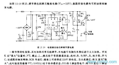
As the figure 15-30 shows, the regulator is composed of the step-down rectifier circuit (VDD=13V), the oscillation control circuit and the silicon controlled phase shifting trigger circuit.
When the switch K is at the strong fire position, the VT2 cuts off, the contact point J1-1 is in the NC connection state, at this time R1 is in parallel with the RP1 and R2, and the RC trigger network is composed of the R1 and C1, after the SCR is conducted, the socket can get the 220V voltage. When the water is boiled, you dial the switch K to the mini fire position, the temperature sensor VT1 (3AX31) is in the heat conduction state, the pin-2 of 555 has the low electrical level, so the 555 sets, pin-3 has the high electrical level, VT2 conducts, J closes and J1-1 releases.
(View)
View full Circuit Diagram | Comments | Reading(1480)
Recorder remote display circuit
Published:2011/5/25 20:50:00 Author:Christina | Keyword: Recorder, remote display
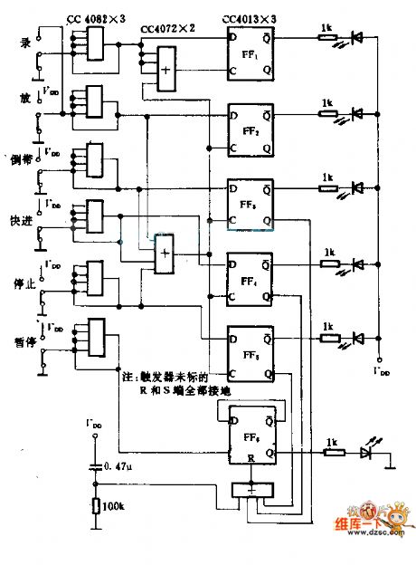
The CC4082 connects into the positive feedback, and trigger is composed of the CC4082 and the bar function switch to guarantee the output electrical signals has no jitter. The or door or the trigger simulates the operating logic of the recorder to make the six LEDs respectively indicate the states of recording, playing, tape rewinding, FF, stop and the pause.
The CC4013 drives the light-emitting diode directly, the current limiting is 4 to 5mA. You can choose the Q port to drive the LED, the purpose is the Q port and the logic stance is irrelevant. If the output current reduces when it is over-driving, it will not influence the logical state of Q.
(View)
View full Circuit Diagram | Comments | Reading(670)
PID control circuit
Published:2011/5/25 21:35:00 Author:Christina | Keyword: PID, control circuit
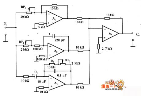
The PID control circuit is as shown, it is the proportion (P), integral (I) and the differential (D) control circuit. The proportion circuit which is composed of A1 is related with the loop gain, by adjusting RP1, you can change the inverter gain in the range of 0.5 to ∞; it is also the integral circuit, the integral time constant can be changed in the range of 22 to 426S; A3 is the differential circuit, the time constant is decided by the Cl(Rl+R(RP3)); A4 outputs the proportion, integral and differential circuits to the phase inversion to compose the U.
(View)
View full Circuit Diagram | Comments | Reading(8962)
Special breeding temperature control and sea wave sound circuit
Published:2011/5/26 7:49:00 Author:Christina | Keyword: breeding temperature, sea wave, sound circuit
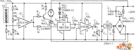
As the figure shows, it is composed of the temperature sensing device, the comparison circuit, the silicon-controlled rectifier control cooling circuit, the sea wave sound circuit and the AC step-down rectifier circuit.etc. This circuit has some points of features such as the wide temperature control range, the high control accuracy and the circuit is simple, practical.
(View)
View full Circuit Diagram | Comments | Reading(870)
Agricultural Automatic Water Feeder (18)
Published:2011/5/25 6:02:00 Author:Sue | Keyword: Agricultural, Automatic, Water Feeder
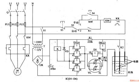
When the level is lower than b, D6 outputs low level, D5 outputs high level. D1-D4 output low level. VL is red. K is connected. KM is connected. M begins to feed water.
When the level reaches c, D6,D1-D4 output high level. K and KM are released. M stops working. When the level is lower, D6 outputs high level, M doesn't work. When the level is lower than b, M begins to work.
The circuit works in such a way to keep the level moving between b and c. (View)
View full Circuit Diagram | Comments | Reading(584)
Agricultural Automatic Water Feeder (17)
Published:2011/5/25 5:58:00 Author:Sue | Keyword: Agricultural, Automatic, Water Feeder
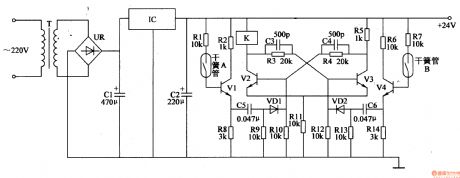
When the level doesn't reach the highest point, V2 is connected and V3 is disconnected. K is connected. M begins to feed water.
When the level reaches the highest point, V4 is connected. V3 V2 are disconnected. K is released. M stops working.
When the level reaches the low level, V1 and V2 are connected, V3 is disconnected. K is connected and M begins to work again.
The circuit works in such a way to keep the water level moving between the highest and the lowest. (View)
View full Circuit Diagram | Comments | Reading(621)
Agricultural Automatic Water Feeder (16)
Published:2011/5/25 5:55:00 Author:Sue | Keyword: Agricultural, Automatic, Water Feeder
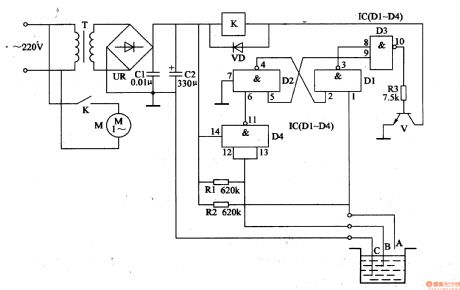
When the level is lower than B, D4 outputs low level, RS will reverse. D3 outputs high level. V and K are connected. M begins to feed water.
When the level is higher than B, D4 outputs high level, M keeps feeding water.
When the level reaches A, IC's 1 pin has low level, RS will reverse and D3 outputs low level. V is disconnected and K is released. M stops working.
When the level is lower than A, IC's 1 pin will become high level. When the level is lower than B, the circuit works like above, keeping the level moving between A and B. (View)
View full Circuit Diagram | Comments | Reading(632)
HIC1015 protection circuit
Published:2011/5/26 8:15:00 Author:Christina | Keyword: protection circuit
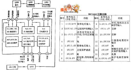
The HIC1015 protection circuit is as shown:
(View)
View full Circuit Diagram | Comments | Reading(985)
Sharp C-1460 protection circuit
Published:2011/5/26 7:58:00 Author:Christina | Keyword: Sharp, protection circuit
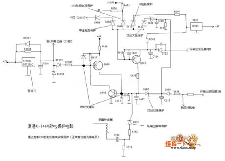
The Sharp C-1460 protection circuit is as shown:
(View)
View full Circuit Diagram | Comments | Reading(872)
The voltage adjuster and contrast control circuit
Published:2011/5/25 22:19:00 Author:Christina | Keyword: voltage adjuster, contrast control
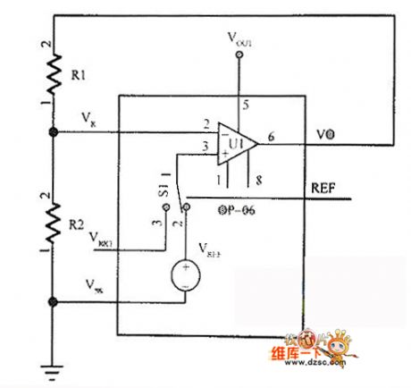
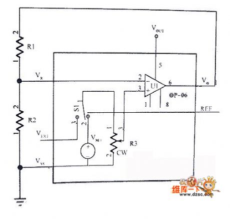
The voltage regulator circuit can be used to get a proper LCD display driver voltage. This voltage is decided by the R1 and R2. The voltage regulator circuit is as shown in the following figure.
The voltage adjustment has 32 contrast ratio stages. When you are using the contrast ratio to control the functions, the voltage regulator needs to open by the power control instruction. The contrast ratio control circuit is as shown. (View)
View full Circuit Diagram | Comments | Reading(683)
555 automatic speed governor circuit
Published:2011/5/19 22:11:00 Author:Christina | Keyword: automatic speed governor
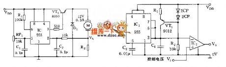
The circuit is as shown, the motor automatic speed governor circuit is composed of the 555 trigger and a switch tube. R7 and the motor is tandem connection to form the sampling circuit. In the motor regulation speed, the sampling voltage VA<1/3VDD, 555 sets, VT1 conducts and the motor gets power to work; when the speed is overrun, VA>1/3VDD, because the connection of R1, the 555 resets, the VT1 cuts off and the motor has no power, when VA<1/3VDD, the 555 sets, VT1 conducts and the motor gets power to work. (View)
View full Circuit Diagram | Comments | Reading(491)
Photoelectric Control Circuit
Published:2011/5/21 0:45:00 Author:Robert | Keyword: Photoelectric, Control
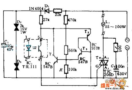
In this circuit, IC1 is a optocoupler. When the LED is lighting, the phototransistor would be connected to trigger the SCR TIC206D connected. So this would contact and connect the large power AC load. The AC electricity would be added on the regulator D2, D3 and C1 through R, D1's voltage step-down and rectifier. Then it produces 30V DC voltage. T1, T2 and T3 are zero-crossing detection circuit. When the AC commercial power cross the zero stage it would trigger the SCR tobegin the soft-starting process.
(View)
View full Circuit Diagram | Comments | Reading(894)
Air condition remote controller circuit
Published:2011/5/30 3:18:00 Author:Christina | Keyword: Air condition, remote controller
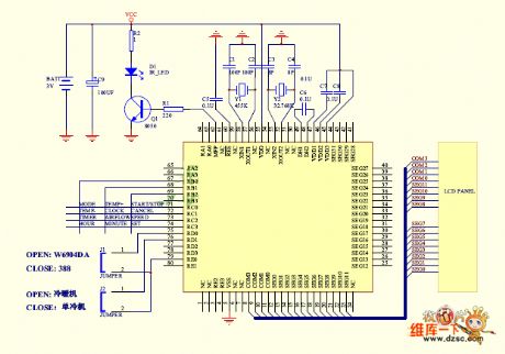
The Air condition remote controller circuit is as shown:
(View)
View full Circuit Diagram | Comments | Reading(785)
JVCAV-S33 power supply protection circuit
Published:2011/5/30 2:21:00 Author:Christina | Keyword: power supply, protection circuit
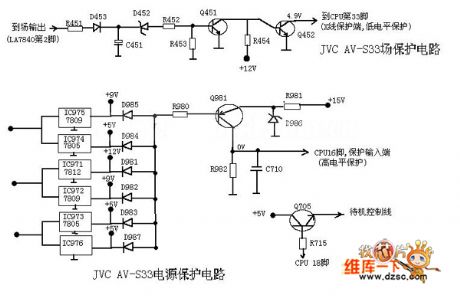
During normal working, the field output has enough pulse output, and the voltage which is rectified and filtered by the D451 and C451 conducts the D452, the Q425 cuts off, the Q452 has the high electrical level.
(View)
View full Circuit Diagram | Comments | Reading(693)
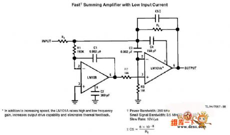
fast summing amplifier with low input current circuit
Published:2011/5/29 21:43:00 Author:chopper | Keyword: fast summing amplifier, low input current
View full Circuit Diagram | Comments | Reading(940)
LF347/LF147 quad operational amplifier circuit
Published:2011/5/29 7:39:00 Author:chopper | Keyword: quad operational amplifier
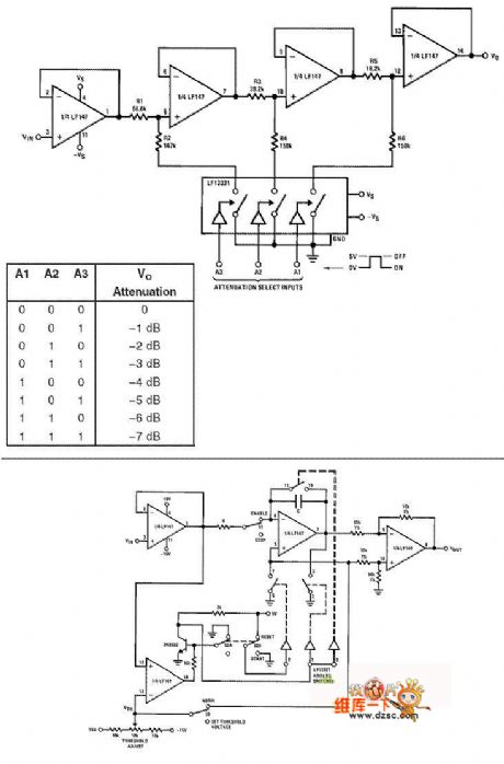
View full Circuit Diagram | Comments | Reading(965)
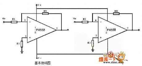
F4558 operational amplifier circuit
Published:2011/5/29 7:26:00 Author:chopper | Keyword: operational amplifier
View full Circuit Diagram | Comments | Reading(12014)
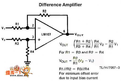
difference amplifier circuit
Published:2011/5/28 0:54:00 Author:chopper | Keyword: difference amplifier
View full Circuit Diagram | Comments | Reading(1005)
LM324 four-Stage Amplifier circuit
Published:2011/5/28 0:27:00 Author:chopper | Keyword: four-Stage Amplifier
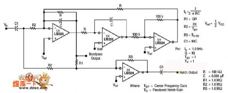
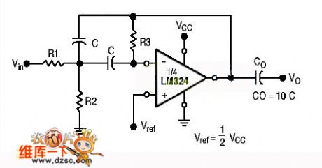
Four-Stage Amplifier circuit ,14 pins dual-in-line package filter is shown as follows.Active band-pass filter circuit is shown as follows:
Spectrum analyzer of acoustics uses this circuit as band-pass filter to select different signals from different frequency ranges,and indicates the scope of signals by using the amount of dots on a monitor lighted by LED.The circuit is shown as follows:
(View)
View full Circuit Diagram | Comments | Reading(6593)
555 simple light controller circuit
Published:2011/5/21 7:25:00 Author:TaoXi | Keyword: simple, light controller
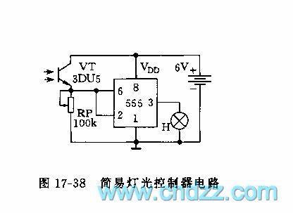
As the figure 17-38 shows, this circuit uses the 555 as the core, and the RS trigger circuit is composed of the 555, the photosensitive tube (3DU type) and the RP. At night, the resistance between 3DU tube's c electrode and e electrode is so large, pin-2's potential closes to the ground potential, 555 sets, pin-3 has the high level voltage, and the light turns on; during the day, there is the illumination, so the resistance between 3DU tube's c electrode and e electrode reduces, pin-6's voltage exceeds the threshold level 2/3VDD, 555 resets, the light turns off.
(View)
View full Circuit Diagram | Comments | Reading(628)
| Pages:257/312 At 20241242243244245246247248249250251252253254255256257258259260Under 20 |
Circuit Categories
power supply circuit
Amplifier Circuit
Basic Circuit
LED and Light Circuit
Sensor Circuit
Signal Processing
Electrical Equipment Circuit
Control Circuit
Remote Control Circuit
A/D-D/A Converter Circuit
Audio Circuit
Measuring and Test Circuit
Communication Circuit
Computer-Related Circuit
555 Circuit
Automotive Circuit
Repairing Circuit