
Control Circuit
Index 248
555 writing table lamp timing control circuit
Published:2011/5/23 1:42:00 Author:TaoXi | Keyword: writing, table lamp, timing control
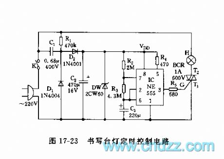
As the figure 17-23 shows, the control circuit is composed of the capacitor step-down rectifier circuit, the low-frequency oscillator circuit and the control circuit. This circuit can automaticly control the light toturn on for 50 minutes and turn off for 10 minutes, then turns on again, so it can protect your eyesight and health.
The astable multivibrator is composed of the 555 and the R2,R3,C3, the oscillation frequency f=1.44/(R2+2R3)C3, the capacitor C3's charging time t=1.1(R2+R3)C3, the discharging time t=1.1R3C3. The pin-5 of control port connects to the VDD to improve pin-6's threshold level.
(View)
View full Circuit Diagram | Comments | Reading(649)
Motor protector circuit diagram 17
Published:2011/5/29 2:01:00 Author:Lucas | Keyword: Motor protector
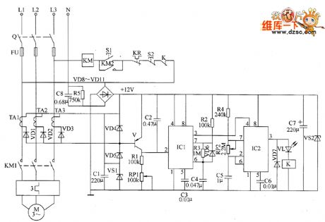
The motor protection circuit is composed of the phase pulse detection circuit, monostable trigger circuit, control circuit and power supply circuit, the circuit is shown as the chart. Phase pulse detection circuit is composed of the current transformers TA1 ~ TA3, diodes VD1 ~ VD5, Zener diode VS1 and capacitor C1. Monostable trigger circuit is composed ofthe transistor V, resistors R1 ~ R3, potentiometer RP1, capacitors C2 ~ C4, diode YD6 and time-based integrated circuit IC1. Delay control circuit is composed of the time-base integrated circuit IC2, resistor R4, capacitors C5, C6, diode VD7, light-emitting diode VL, relay K and AC contactor KM and other components. Power supply circuit consists of step-down capacitor C8, resistor R5, rectifier diodes VD8 ~ VD11, filter capacitor CT and blocking diode VS2.
(View)
View full Circuit Diagram | Comments | Reading(1120)
Motor electronic speed controller circuit diagram 2
Published:2011/5/29 2:03:00 Author:Lucas | Keyword: Motor, electronic speed controller
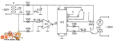
The motor electronic speed controller circuit consists of power supply circuit, the zero detection circuit and the power conditioning circuit, the circuit is shown as the chart. Power supply circuit is composed of the power transformer T, rectifier diodes VD1, VD2, and filter capacitor C. Zero detection circuit is composed of the diodes VD3, VD4, resistor R1 and Op Amp IC IC1. Power conditioning circuit consists of counting / divider integrated circuit IC2, power adjusting switch S, the diodes VD5, VD6, resistors R2, R3, transistor V and control V and thyristor VT. R1 ~ R3 use 1/4W carbon film resistors or metal film resistors. C uses aluminium electrolytic capacitor with the voltage in 25V. VD1 ~ VD6 use 1N4007 silicon rectifier diodes. V uses 59013, C8050 or 58050 silicon NPN transistor.
(View)
View full Circuit Diagram | Comments | Reading(1926)
Motor protector circuit diagram 14
Published:2011/5/29 2:01:00 Author:Lucas | Keyword: Motor protector
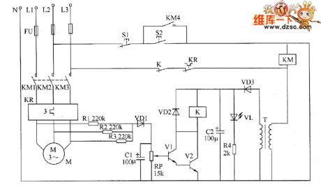
The motor protector circuit is composed of the power detection circuit and phase failure protection circuit, the circuit is shown as the chart. Power circuit is composed of the power transformer T, rectifier diode VD3, filter capacitor C2, current limiting resistor M and LED VL. Phase failure detection protection circuit consists of resistors R1 ~ R3, capacitor C1, diodes VD1, VD2, potentiometer RP, transistors V1, V2 and relays Κ and so on. R1 ~ R3 select 1/2W metal film resistors; Ⅲ uses the carbon film 1/4W resistor or metal film resistor. RP selects membrane potentiometer or variable resistor. C1 and C2 select aluminium electrolytic capacitor with the voltage in 16V. VD1 ~ VD3 select 1N4004 or 1N4007 diode rectifier. VL uses φ5mm ordinary light-emitting diode.
(View)
View full Circuit Diagram | Comments | Reading(905)
555 multi-function appliance protector circuit
Published:2011/6/2 1:02:00 Author:TaoXi | Keyword: 555, multi-function, appliance, protector
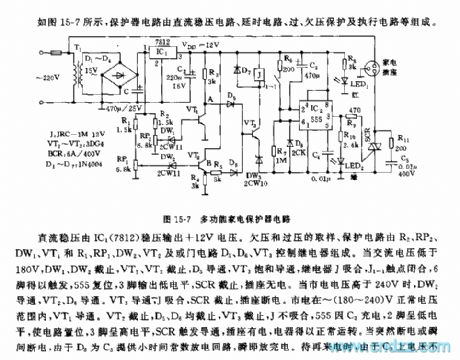
As the figure 15-7 shows, the protector circuit is composed of the DC voltage-stabilizing circuit, the delay circuit, the over-voltage under-voltage protection circuit and the execution circuit.etc.
The IC1(7812) outputs the +12V DC voltage. The over-voltage under-voltage protection circuit is composed of the R2, RP2, DW1, VT1 and R1, RP1, DW2, VT2 and the NAND gate circuit D5,D6, the relay control VT3.etc. When the AC voltage is lower than 180V, the DW1 and DW2, VT1, VT2 cut off, D5 conducts and the VT3 is saturated conduction, the realy J closes, the contact point of J1-1 closes, pin-6 triggers, 555 resets, pin-3 outputs the low electrical level, SCR cuts off, the socket has no power. When the city electricity voltage is higher than 240V, DW2, VT2, D6 conduct.
(View)
View full Circuit Diagram | Comments | Reading(981)
Motor protector circuit diagram 13
Published:2011/5/29 2:03:00 Author:Lucas | Keyword: Motor protector
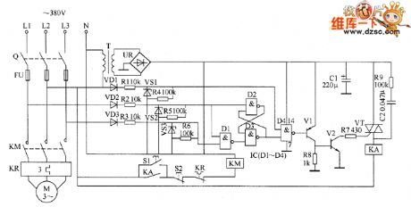
The motor protector circuit is composed of the power circuit, phase sequence detection circuit, trigger, and protection control circuit, the circuit is shown as the chart. Power circuit is composed of the power transformer T, bridge rectifier UR and filter capacitor C1. Phase sequence detection circuit is composed of the diodes VD1 ~ VD3, resistors R1 ~ R6 and Zeners VS1 ~ VS3. Trigger is composed of the D1 ~ D4 in the NAND gate IC. Protection control circuit consists of transistors V1, V2, resistors R7 ~ R9, capacitor C2, thyristor VT, and relay KA. Start button S1, stop button S2, knife switch Q, fuse FU, thermal relays KR and KM form the original control circuit of motor. R1 ~ R3 and R9 select 1W metal film resistors; M ~ R8 select 1/4W carbon film resistor or metal film resistors.
(View)
View full Circuit Diagram | Comments | Reading(2410)
Motor protector circuit diagram 6
Published:2011/6/8 3:55:00 Author:Lucas | Keyword: Motor protector
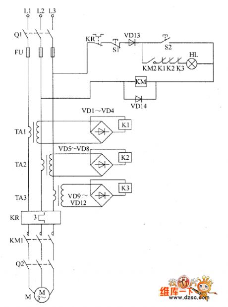
The motor protector circuit is composed of the current transformers TA1 ~ TA3, thermal relay KR, rectifier diodes VD1 ~ VD14, relays K1 ~ K3, start button S1, stop button S2 and AC contactor KM, the circuit is shown as the chart. After the the knife switch Q1 is turned on and the start button S2 is pressed, 380V AC voltage between the phase line L2 and L3 is added to the AC contactor KM by the normally closed contacts of relay KR, stop button S1, diode D13 and start button QO, and KM will operate normally, and its normally open contacts ( action contacts) KM1 and KM2 are connected, at this time if the knife switch Q2 is connected, the motor M will be energized operation. VD1 ~ VD14 use 1N4007 silicon rectifier diodes. K1 ~ K3 select JRX-13F 12V small relays. KM uses 220V or 380V AC contactor. HL uses 220V, 60W incandescent bulb.
(View)
View full Circuit Diagram | Comments | Reading(771)
555 anti-interference light control circuit
Published:2011/5/23 22:20:00 Author:TaoXi | Keyword: anti-interference, light control circuit
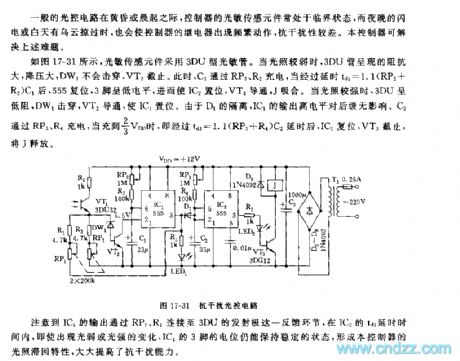
General optical circuit's photosensitive sensor is in the critical state in the evening or early morning. And the night lightning or the daytime clouds will cause the frequent movement of the relay controller, the anti-interference performance is poor. This controller can solve the above problem.
As the figure 17-31 shows, the photosensitive sensor uses the 3DU type photosensitive tube. When the illumination is weak, the 3DU tube presents the big impedance and big depressurization, DW1 will not bebroken through, VT2 cuts off. At this time, C1 is charged through RP2 and R2. After the delay time of td1=1.1(RP2+R2)C1, 555 resets, pin-3 has the low level voltage, and IC2 sets, VT3 conducts, J closes.
(View)
View full Circuit Diagram | Comments | Reading(527)
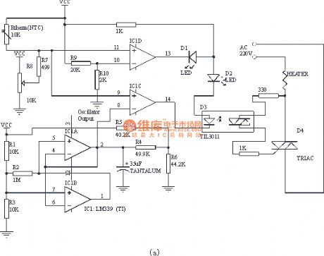
Constant temperature controller circuit with the four-comparator
Published:2011/5/17 21:38:00 Author:TaoXi | Keyword: Constant temperature, controller, four-comparator
Related components PDF download:
LM339TIL3011
This controller is the PWM type, but it has the index transfer characteristics but not the linearity. This design is based on a LM339 (four-comparator) and contains the temperature compensation. Because the comparator's temperature drift will produce the Vos change and cause the change the oscillator output. However, in the comparator of producing the working cycle, the same change has taken place, they offset each other to eliminate the drift of the controller.
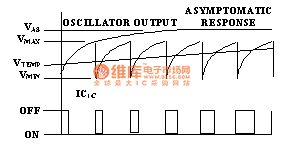
The core of the controller is the oscillator which is composed of the IC1a, IC1b and other related components. The main factors of the controller precision are the peak value and the minimum voltage of the oscillator's output voltage. The oscillator has the following formulas:
PERIOD=[R5×R6/(R5+R6)+R4]×C1×Ln[(Vas-Vmin)/(Vas-Vmax)] seconds
DutyCycle=Ln[(Vas-Vtemp)/(Vas-Vmax)] / Ln[(Vas-Vmax)/(Vas-Vmin)]
Vmax=Vcc×R3/(R1+R3)
Vmin=Vcc×R2×R3/[R2×R3+R1×(R2+R3)]
Vas=Vcc×R6/(R5+R6)
Vtemp=Vcc×(R7+R8)/(Rtherm+R7+R8)
Figure 1. Constant temperature controller circuit
(View)
View full Circuit Diagram | Comments | Reading(1802)
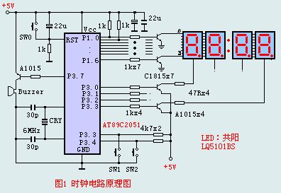
The clock timing principle circuit
Published:2011/5/17 22:52:00 Author:TaoXi | Keyword: clock, timing, principle circuit
Related components PDF download:
AT89C2051A1015C1815
In the internal RAM of the single chip microcontroller, we need to set the display buffers, the hours, minutes and seconds values are took out from the display buffers, so we set four units as the display buffers in RAM, they are 7AH,7BH and 7CH. To make the circuit and the principle narrative more convenient, we don't display the second value, we realize the second binary by flashing score. So we have 4 bits LEDs to display the hour value and the minute value. Meanwhile all the clocks need to be calibrated. The program also needs to install the display code meter.
(View)
View full Circuit Diagram | Comments | Reading(714)
The electric adjuster circuit of touch fans
Published:2011/6/10 0:54:00 Author:qqtang | Keyword: electric adjuster, touch fans
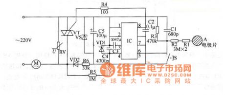
The working principle of the circuitThe adjuster circuit consists of the integrated circuit IC, two-way thyristor VT and external elements, see as figure 1.
When it is in the mains of 200v, the speed regulator is starting to work, but the two-way thyristor is blocked and the fan motor M is still. When the hand touches the electrode plate and the touching time is not less than 0.4s, the 8-pin if IC outputs a solid high LEV, then the thyristor is conducting and M begins to run. However, the speed regulator just works as a switch. (View)
View full Circuit Diagram | Comments | Reading(602)
TC9308AF-029--the system control microcomputer integrated circuit
Published:2011/6/10 0:57:00 Author:qqtang | Keyword: system control, integrated circuit
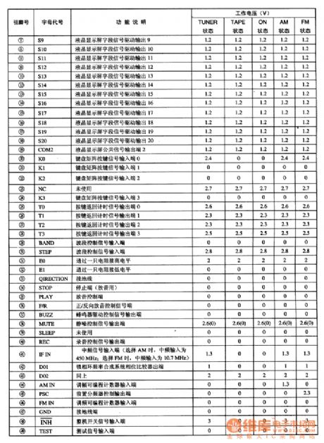
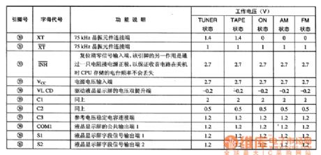
TC9308AF-029 is a system control microcomputer integrated circuit produced by Toshiba, which is widely used in walkmen and function control, such as Aiwa, Sanyo and Toshiba, etc.1.function featuresTC9308AF-029 contains the CPU, clock oscillating circuit, key pulse counter, preset frequency distributor, reset control circuit, wave control circuit, reproduce control circuit, recording control circuit, system and LCD display decoding drive circuit, etc.2.pin functions and data
(View)
View full Circuit Diagram | Comments | Reading(838)
High sensitivity alarm circuit
Published:2011/6/9 2:19:00 Author:Christina | Keyword: High sensitivity, alarm
The high sensitivity alarm circuit is as shown in the figure, the photoconductive resistance LDR is connected with three ordinary resistances.
The alarm sensor circuit is as shown in the figure. In this circuit, the half of the CMOS integrated timer 7556 is connected as the self-excited oscillator, the IC2c constitutes the equivalent inverter, the oscillator is under the function of IC2c to complete the alternate connection. The IC2a and IC2b are the two-node switch. The input impedance if the IC2's control pin is very high, so the load is very light for the IC1a, the voltage dividing network is composed of the R3, R4, R5, R6, the photoconductive resistance and the LDR, this makes the X point has the required potential to charge the C4 and C5 through the double node switch.
(View)
View full Circuit Diagram | Comments | Reading(794)
555 light control stroboscopic type security light circuit
Published:2011/5/22 8:14:00 Author:TaoXi | Keyword: light control, stroboscopic type, security light
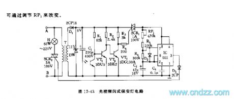
As the figure 17-43 shows, the circuit is composed of the step-down rectifier circuit, the photoelectric switch circuit and the stroboscopic oscillation & control circuit, this circuit can be used in wide range of applications such as the construction scene and the road scene to remind the people to pay attention.
At night, the photoelectric switch circuit which is composed of the 3DU5, the VT2 and VT3 amplifiers is in the conduction state, SCR1 triggers the conduction, the IC oscillator starts working, it conducts and cuts off the SCR2 with its oscillation frequency, so the lamp H shines to remind the people. The light flash frequency f=1.44/(RP1+R5+R6)C2.
(View)
View full Circuit Diagram | Comments | Reading(923)
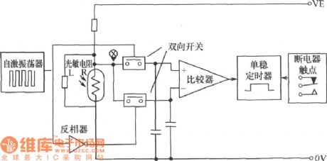
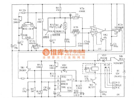
555 amplification exposure time automatic controller circuit
Published:2011/5/24 2:53:00 Author:TaoXi | Keyword: amplification, exposure, time, automatic controller
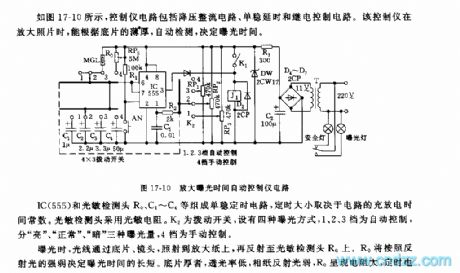
As the figure 17-10 shows, the controller circuit is composed of the step-down rectifier circuit, the monostable delay circuit and the relay control circuit. When the controller is amplifying the photo, it can automatic detect the thickness of the negative film to decide the exposure time.The monostable timing circuit is composed of the IC(555) and the photosensitive detection head R0, the C1~C4.etc.
The timing length is determined by the circuit's charge-discharge time constant. The photosensitive detection head uses the photoconductive resistance, K2 is the toggle switch and it has four kinds of exposure method, 1,2,3 tap positions are the automatic control, there is three kinds of exposure value: light , normal and dark , the fourth gear is the manual control gear.
(View)
View full Circuit Diagram | Comments | Reading(603)
555 automatic circulating seven colors color-light control circuit
Published:2011/5/22 19:55:00 Author:TaoXi | Keyword: automatic circulating, seven colors, color-light, control circuit
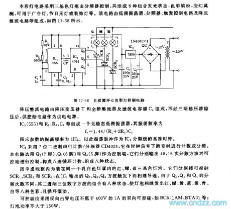
This color-light circuit uses the three-color light bulb which is controlled by the frequency divider, it has eight kinds of combination luminous states, it is colorful and unpredictable. So this circuit can be used in wide range of applications such as the advertising lights, the holiday lights and the decorative lights. This circuit is composed of the low frequency oscillator, the frequency divider, the trigger control circuit and the step-down rectifier circuit.etc. As the figure 17-58 shows.
The step-down rectifier circuit is composed of the step-down transformer T, the bridge rectifier and the filter capacitor C4.
The no steady-state low-frequency oscillator is composed of the IC1(555) and R1,R2,C1, the oscillation frequency fc=1.44/(R1+2R2)C1.
(View)
View full Circuit Diagram | Comments | Reading(781)
555 DGK—45L disinfection cabinet electronic control circuit
Published:2011/5/25 3:09:00 Author:TaoXi | Keyword: 555, disinfection cabinet, electronic control
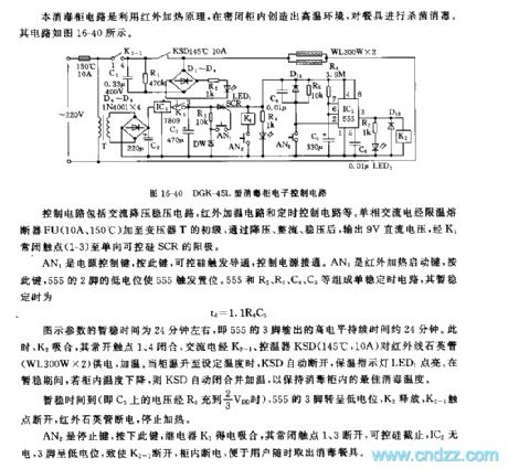
The control circuit is composed of the AC step-down voltage stabilization circuit, the infrared heating circuit and the timing control circuit.etc. The single phase alternating current adds to the primary stage of the transformer T through the temperature limit fuse FU(10A, 150℃), after the function of step-down, rectification and voltage stabilization, the transformer T outputs the 9V DC voltage, this voltage adds to the single phase SCR's positive electrode through K1's normal closing contacts (1-3).
AN1 is the power control button, you can conduct the SCR and control the connection of the power supply by pressing this button. AN3 is the infrared heating start button, if you press this button, the low electric potential of the 555 pin-2 sets the 555. The monostable timing circuit is composed of the 555 and R5,R6,C4,C5, the Temporary stabilization time td=1.1R6C5.
(View)
View full Circuit Diagram | Comments | Reading(535)
555 home appliance timing power-off controller circuit
Published:2011/6/7 0:56:00 Author:TaoXi | Keyword: 555, home appliance, timing, power-off, controller
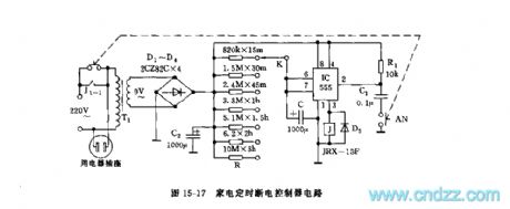
As the figure 15-17 shows, the timing power-off control circuit is composed of the step-down rectifier circuit and the timing circuit.etc. When you press the button switch AN, the electric potential of 555's pin-2 is lower than the trigger electrical level 1/3VDD, so the 555 circuit turns, pin-3 outputs the high electrical level, the relay J closes and the J1-1 contact point closes too, the socket gets the power, the circuit starts timing at this time. The capacitance C is charged through R, when the voltage of C is higher than the threshold level 2/3VDD, 555 circuit resets, pin-3 has the low electrical level, J releases and J1-1 cuts off, the appliance has no power.
(View)
View full Circuit Diagram | Comments | Reading(595)
555 household appliance products long timing circuit
Published:2011/6/7 1:40:00 Author:TaoXi | Keyword: 555, household appliance, products, long timing
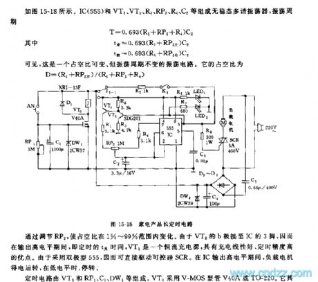
As the figure 15-18 shows, the astable multivibrator is composed of the IC(555) and VT1, VT2, R1, RP2, R4, C2, the oscillation period T=0.693(R1+RP2+R4)C2.
Because the b electrode of VT2 connects to the pin-3 of IC, so when pin-3 outputs the high electrical level, VT1 is a constant-current charging source, it has good charging linear and timing precision. Because it uses the bipolar type 555, so it can drive the SCR directly. When the IC outputs the high electrical level, the load gets power to work, when the IC outputs the low electrical level, the load has no power to work.
The timing circuit is composed of the VT3 and RP1, C1, DW1.etc. The VT3 uses the VCMOS type tube V40A or TO-220.
(View)
View full Circuit Diagram | Comments | Reading(471)
555 household time-limit alarm circuit
Published:2011/6/7 2:25:00 Author:TaoXi | Keyword: 555, household, time-limit, alarm
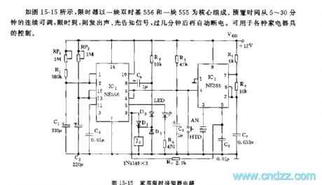
As the figure 15-15 shows, the preset timer uses one piece of dual time-base 556 and one piece of 555 as the core. The preset time is 5 to 30 minutes, when the time is up, this circuit will send out the sound-light alarm signal, and after a few minutes, this circuit will cut off the power automaticly. It can be used to control all sorts of home appliances.
The RP1, R1, C1 and 1/2 556 can be used in the 5 to 30 minutes boot timing. When the power supply opens, the C1's electric potential can not be mutated, so the timing circuit sets and the timeing starts, the timing time td1=1.1(RP1+R1)C1, you can change the timing length by adjusting RP1. The monostable delay circuit is composed of the RP2, C2 and another half of 556, the delay time depends on the time constants of RP2 and C2.
(View)
View full Circuit Diagram | Comments | Reading(900)
| Pages:248/312 At 20241242243244245246247248249250251252253254255256257258259260Under 20 |
Circuit Categories
power supply circuit
Amplifier Circuit
Basic Circuit
LED and Light Circuit
Sensor Circuit
Signal Processing
Electrical Equipment Circuit
Control Circuit
Remote Control Circuit
A/D-D/A Converter Circuit
Audio Circuit
Measuring and Test Circuit
Communication Circuit
Computer-Related Circuit
555 Circuit
Automotive Circuit
Repairing Circuit