
Control Circuit
Index 243
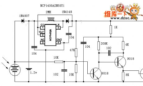
The auto tracking controller circuit of solar power
Published:2011/6/23 22:06:00 Author:Seven | Keyword: auto tracking controller, solar power
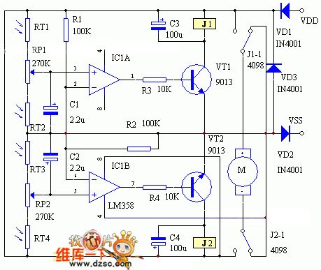
There are two kinds of auto tracking controllers of solar power: one is that a LDR and Schmidt trigger or a single stable trigger compose a light controlled Schmidt trigger or single stable trigger, which is to control the running/stopping of the motor; the other is that two LDR and two comparators respectively compose two light controlled comparators that control the motor. As the light and its strength change a lot in different seasons and hours, so it's hard for the above controllers to make the solar tracking equipment follow the sun.
(View)
View full Circuit Diagram | Comments | Reading(3778)
Switch type voltage stabilizer circuit composed of the CW1842
Published:2011/6/21 1:15:00 Author:Christina | Keyword: Switch type, voltage stabilizer
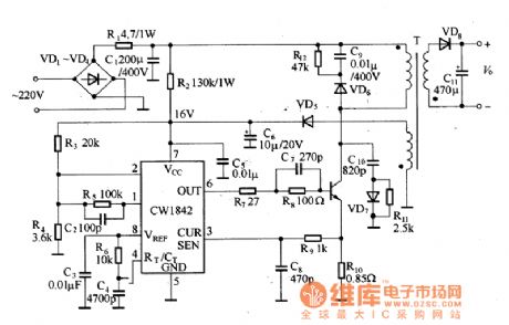
The single port flyback transforming type switch power supply circuit is as shown in the figure, the input voltage is 220V AC.
Switch type voltage stabilizer circuit composed of the CW1842
The output voltage depends on the subprime circle number of T, R2 is the input resistance of CW1842. (View)
View full Circuit Diagram | Comments | Reading(3594)
The double purpose desk lamp circuit of dimming and timing
Published:2011/6/24 3:03:00 Author:Seven | Keyword: double purpose, desk lamp
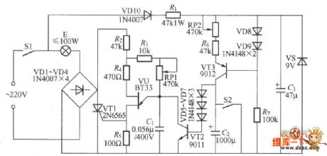
The figured lamp circuit can not only casually regulate the light, but also has the function of timing and putting out the light, which consists of the thyristor light regulating circuit and thyristor time delay circuit, two parts in total.
(View)
View full Circuit Diagram | Comments | Reading(787)
The non-stage regulated sunlight lamp circuit
Published:2011/6/24 2:55:00 Author:Seven | Keyword: non-stage, regulated, sunlight lamp
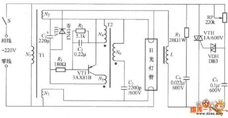
The non-stage regulated sunlight lamp circuit is shown in the figure, which consists of the regulated circuit, high frequency oscillator and filament transformer. The regulated circuit consists of the two-way thyristor VTH, two-way trigger diode VDH and the resistance-capacitance phase-drifting circuit. By regulating the potentiometer, the conducting angle of the thyristor VTH can be changed, which makes the DC voltage on the two terminals of the sunlight lamp change, so that the aim to regulate the light of the lamp is achieved. VT1 must be the Ge intermediate triode of 3AX818 type, β≥60, Iceo would better be low.
(View)
View full Circuit Diagram | Comments | Reading(682)
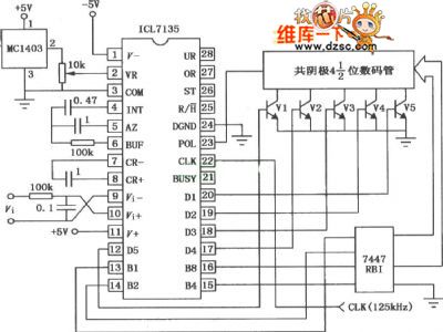
ICL7135 A / D converter application circuit
Published:2011/6/25 9:38:00 Author:John | Keyword: A / D converter
View full Circuit Diagram | Comments | Reading(5676)
Three-port fixed integrated voltage stabilizer circuit
Published:2011/6/23 8:19:00 Author:Christina | Keyword: Three-port, fixed, integrated, voltage stabilizer
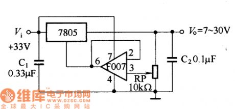
The 7~30V adjustable voltage stabilizer circuit which is composed of the CW7805 integrated voltage stabilizer is as shown in the figure. The F007 operational amplifier is the voltage follower, its operating voltage is directly from the DC voltage input port of the voltage stabilizer.
The 7~30V adjustable voltage stabilizer circuit (View)
View full Circuit Diagram | Comments | Reading(1049)
Capacitive dimmer switch circuit
Published:2011/6/25 9:28:00 Author:John | Keyword: switch
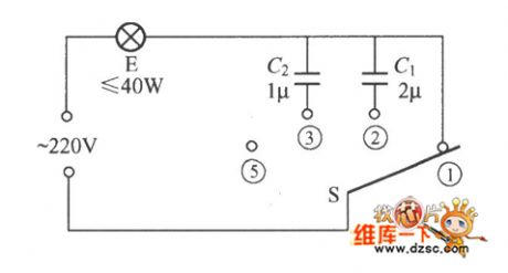
Capacitive dimmer switch circuit is as shown. It uses the principle of capacitance of capacitors for AC. When the S is at the shown position, bulb E normally lights with the maximum brightness. When it is dialed to position ②, light intensity of E decreases because of the insert of 2μF capacitor C1 in series. When it is allocated to the position ③, the brightness is reduced with a block because of increasing capacitance cause by C2 <C1. And when it is allocated to the position ④, the light E is off. C1 and C2 should use non-polar oil paper capacitor which can endure more than 400V voltage. And S is the 1 × 4 single-pole four-throw switch.
(View)
View full Circuit Diagram | Comments | Reading(926)
The single key digital dimmer circuit
Published:2011/6/24 8:00:00 Author:Seven | Keyword: single key, digital dimmer
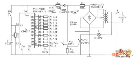
The single key digital dimmer circuit is shown in the figure, which is a thyristor trigger circuit composed of the CD4017 digital circuit and the single knot thyristor. It can adjust the brightness in 10 gears, and it is very convenient to use.
(View)
View full Circuit Diagram | Comments | Reading(3500)
The farm thermostat controller circuit diagram
Published:2011/6/18 21:29:00 Author:Lucas | Keyword: farm, thermostat controller
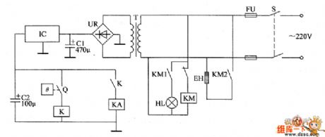
The farm thermostat controller circuit is composed of the power supply circuit and temperature control circuit, and the circuit is shown in the chart. Power supply circuit is composed of the power switch S, fuse FU, power transformer T, bridge rectifier UR, filter capacitors C1, C2, and three-terminal voltage regulator integrated circuit IC. Temperature control circuit consists of electric heating thermometer Q, relay K, intermediate relay KA, AC contactor KM, electric heater EH and heating indicator light HL. C1 and C2 select the aluminum electrolytic capacitor with the voltage above 35V. UR selects the 1 ~ 2A, 50V bridge rectifier. IC selects 78H24 three-terminal regulator IC.
(View)
View full Circuit Diagram | Comments | Reading(619)
Automatic sprinkler controller circuit diagram 2
Published:2011/6/18 21:54:00 Author:Lucas | Keyword: Automatic , sprinkler controller
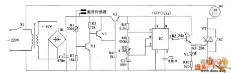
The automatic sprinkler controller circuit is composed of the power supply circuit, switch control circuit, astable oscillator circuit and control implementation circuit, and the circuit is shown in the chart. Power supply circuit consists of the power switch s1, power transformer T, bridge rectifier UR and filter capacitor C1. Switch control circuit consists of the humidity sensor, sampling tube VI, composite amplifier tubes V2, V3, and power filter control resistors R1 ~ R4. Astable multivibrator consists of the time-base integrated circuit IC and the external RC components. Control implementation circuit is composed of the transistor V4, LEDs VL, thyristor VT, and manual control switch S2 and so on.
(View)
View full Circuit Diagram | Comments | Reading(1292)
Automatic feeding controller circuit diagram
Published:2011/6/18 21:35:00 Author:Lucas | Keyword: Automatic, feeding controller
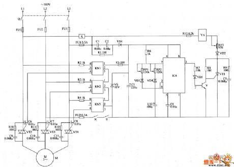
The automatic feeding controller circuit is composed of the power supply circuit, pulse oscillator, electromagnetic control circuit and motor control circuit, and the circuit is shown in the chart. Power supply circuit is composed of the knife switch Q, fuses FU1 ~ FU3, buck capacitors C1, C2, drain resistor R1, control switch S, relay K, rectifier diode VD1, voltage regulator diode VS and filter capacitor C3. Pulse oscillator is composed of the resistor R6, potentiometers RP1, RP2, diodes VD3, VD4, capacitors C4, C12, and time-base integrated circuit IC. The electromagnetic control circuit consists of the electromagnet VA, resistors R7 ~ R9, R13, potentiometer RP3, diodes VD2, VD5, transistor V, capacitor C5 and thyristor VT1.
(View)
View full Circuit Diagram | Comments | Reading(832)
The chicken farm temperature controller circuit diagram
Published:2011/6/18 21:45:00 Author:Lucas | Keyword: chicken farm, temperature controller
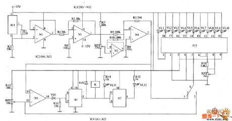
The chicken farm temperature controller circuit consists of temperature detection circuit, temperature control circuit and temperature analog display circuit, and the circuit is shown in the chart. Temperature detection circuit is composed of the integrated temperature sensor IC1, and the the N3, N4 which are inside of operational amplifier integrated circuits IC2 (N1, N2), IC3 (N3 ~ N5), resistors R1 ~ R10 and potentiometer RP1. Temperature control circuit is composed of the N5 which is inside of IC3, diodes VD1, VD2, dual time-base integrated circuit IC4, resistors R12 ~ R15, light emitting diodes VL11, VL12, potentiometer RP2 and relay Κ. Temperature analog display circuit consists of the LED display driver IC IC5, control switch S, resistor R11, potentiometer RP3 and light-emitting diodes VL1 ~ VL10. R1 ~ R15 select the 1/4W carbon film resistors or metal film resistors.
(View)
View full Circuit Diagram | Comments | Reading(2031)
The barton automatic controller circuit diagram
Published:2011/6/18 22:57:00 Author:Lucas | Keyword: barton , automatic controller

The automatic control circuit is composed of the power supply circuit, humidity detection control circuit, light detection control circuit and temperature detection control circuit, and the circuit is shown in Figure 38. Power supply circuit is composed of the power transformer T, bridge rectifier UR1, LED HL, three-terminal integrated regulator IC and filter capacitor C1. Humidity humidity detection control circuit consists of resistor RS, bridge rectifier UR2, potentiometer RP1, transistors V1, V2, diodes VD1, VD2, resistors R1 ~ R4, capacitor C2 and relay K1. Light detection control consists of the photosensitive transistor V3, transistors V4, V5, resistors R5 ~ R8, potentiometer RP2, diodes VD3, VD4, and relay K2. Temperature detection circuit is composed of the thermistor control circuit RT, resistors R9 ~ R12, transistors V6, V7, capacitor C4, potentiometer RP3, diodes VD5, VD6 and relay K3.
(View)
View full Circuit Diagram | Comments | Reading(695)
The electric fence control circuit diagram 9
Published:2011/6/18 22:27:00 Author:Lucas | Keyword: electric fence , control

The electric fence control circuit is composed of the power supply circuit, trigger control circuit, high voltage circuit and alarm circuit, and the circuit is shown in the chart. Power supply circuit is composed of the power switch S1, voltmeter PV, fuse FU, resistors R1, R9, power indicators HL1, HL2, power transformer T1, bridge rectifiers UR1 ~ UR3, capacitors C1, C5, C8, inductor L, ammeter PA, diode VD4 and regulator diode VS. Trigger control circuit is composed of the capacitor C9, potentiometer RP1, resistors R10, R11, single-junction transistor VU, isolation transformer T3 and diode VD6. The high-voltage circuit is composed of diode VD5, thyristor VT2, resistors R7, R8, capacitors C6, C7, neon light HL2 and high-voltage transformer T2.
(View)
View full Circuit Diagram | Comments | Reading(2116)
The multiple alarm circuit
Published:2011/6/23 21:41:00 Author:Seven | Keyword: multiple alarm
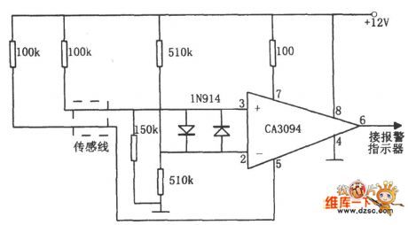
In the figure is the multiple alarm circuit. The circuit consists of the CA3094 integrated circuit, sensing wire, diode and power supply, etc. The figure in the dotted line frame of the circuit is the alarm switch. In the normal condition, the chip CA3094 6-pin is in a high LEV and the alarm is silent. When one of the sensing wire is broken, short or touch the earth, the 6-pin of the chip will be in a low LEV, so the alarm indicator is pushed to work. The circuit can alarm under conditions of broken circuit, short circuit and ground connection, etc.
(View)
View full Circuit Diagram | Comments | Reading(1039)
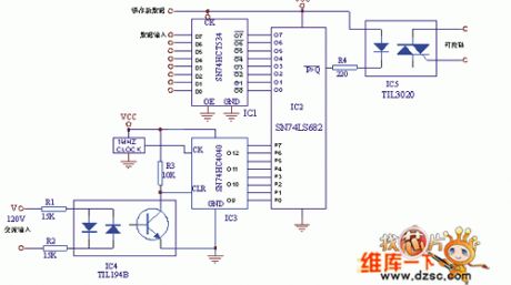
The full-digit dual-way controllable silicon circuit
Published:2011/6/23 10:14:00 Author:qqtang | Keyword: full-digit, dual-way, controllable silicon
View full Circuit Diagram | Comments | Reading(596)
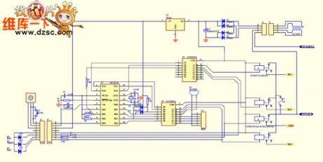
The air-conditioner mainboard and low-cost PIC16C54 circuit
Published:2011/6/23 10:33:00 Author:qqtang | Keyword: air-conditioner, mainboard
View full Circuit Diagram | Comments | Reading(1281)
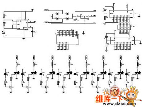
The assembled 8-line color lamp controller circuit
Published:2011/6/23 21:23:00 Author:Seven | Keyword: 8-line, color lamp, controller
View full Circuit Diagram | Comments | Reading(696)
Universal Active Filter circuit
Published:2011/6/15 10:40:00 Author:John | Keyword: Universal Active Filter
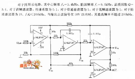
Universal Active Filter circuit is shown below.
Referring to the circuit as shown, its center frequency f0 = 3.4kHz, notch frequency fc = 9.5kHz and quality factor Q = 3.4. Transfer coefficient is 0.1for the high-frequency filter and is 1 for the band pass filter or the low-frequency filter. And 10.f0Q ≤ 200kHz is for the notch filter. When the output sinusoidal signal is with 10V, its highest frequency is not more than 200kHz.
(View)
View full Circuit Diagram | Comments | Reading(1243)
The solar small lighting lamp circuit
Published:2011/6/18 3:01:00 Author:Seven | Keyword: solar, lighting lamp
View full Circuit Diagram | Comments | Reading(799)
| Pages:243/312 At 20241242243244245246247248249250251252253254255256257258259260Under 20 |
Circuit Categories
power supply circuit
Amplifier Circuit
Basic Circuit
LED and Light Circuit
Sensor Circuit
Signal Processing
Electrical Equipment Circuit
Control Circuit
Remote Control Circuit
A/D-D/A Converter Circuit
Audio Circuit
Measuring and Test Circuit
Communication Circuit
Computer-Related Circuit
555 Circuit
Automotive Circuit
Repairing Circuit