
Control Circuit
Index 240
The Butterworth 4-stage switch capacitor low-pass filter (TLC04)
Published:2011/6/17 6:46:00 Author:Borg | Keyword: Butterworth, switch capacitor, low-pass filter
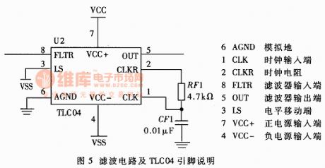
The filter circuit is shown in figure 5. The main part of the filter circuit consists of the Butterworth 4-stage switch capacitor low-pass filter (TLC04) which is produced by TI Corp., US, and the self-timing dual power supply of Schmidt trigger oscillator is the power supply. The stability of TLC04 blocking frequency is only related with the clock frequency stability, the blocking frequency clock is adjustable, the clock-blocking frequency ratio is 50:1, so the designed blocking frequency is 1/1.69×RF1×CF1×50=251.8Hz, which satisfies the requirements of oscillating aging and oscillating wielding technique.
(View)
View full Circuit Diagram | Comments | Reading(859)
Digital clock integral o clock to tell time circuit diagram
Published:2011/6/24 2:34:00 Author:Nicole | Keyword: digital clock, integral o clock to tell time

The timing control circuit is made as the core of LCD digital clock chip KS5195(or KS5194), it out-connects special quartz crystal 32768Hz, the time reference can be precise adjusted by changing the capacitor C0. The integral timing signal is extracted from AL clock control terminal, when it is integral point moment, it outputs a high level signal(Vp-p=1.3V, t=50ms).
IC2 adopts time base circuit 555, the monostable timing circuit is composed of IC2 and R3, C3. When it is integral point moment, VT1 is saturated and turned on by clock control timing pulse, 555's 2 foot is low level, 555 is flipped and set, 3 foot turns to high level. The high level's hold time, namely, the monostable temporary stability time is td=1.1R3C3.
(View)
View full Circuit Diagram | Comments | Reading(728)
Photoelectric control electric tracking toy vehicle circuit diagram
Published:2011/6/24 3:01:00 Author:Nicole | Keyword: photoelectric control, electric tracking toy vehicle
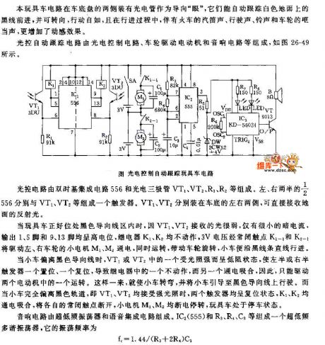
After 555 is triggered, in the period of temporary stability time, the high level which is outputed by 3 foot provides IC2 with work voltage. IC2 adopts analogue integrated circuit KD-5602, it contains didida general title sound, the music is about 10s. Once this chip obtains electricity and triggers, the general title sound will be performed, it is amplified by VT2, it drives loudspeaker to phonate. The typical work voltage of KD-5602 is +3V, so R4, DW steady voltage circuit are connected into circuit, 2CW51 provides +3V voltage. KD-5602's static power is tiny(Iab<1μA), the peripheral devices are few. R5, C5 are chip oscillator's external resistor capacitor components, the oscillation frequency or tone can be changed by adjusting RC time constant.
(View)
View full Circuit Diagram | Comments | Reading(643)
Body induction music fountain switch circuit diagram
Published:2011/6/24 3:32:00 Author:Nicole | Keyword: body induction, music, fountain switch
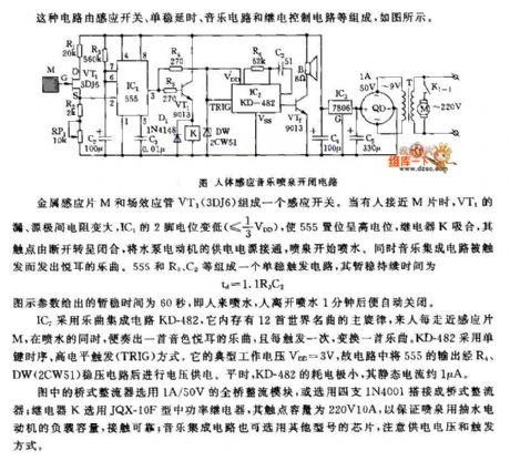
The circuit is composed of inductive switch, monostable delay, music circuit and relay control circuit, the figure is as shown.
A inductive switch is made of metal sensor chip M and FET VT1(3DJ6). When somebody closes M chip, VT1's drain-to-source resistance increases, IC1's 2 foot level drops(≤1/3 VDD), 555 is set and it is high level, relay K pulls in, the contact turns from off to closed, the electric motor of water pump's power supply is connected, the fountain starts to spray water. At the same time, the music integrated circuit is triggered, and it sends out euphonious music. A monostable trigger circuit consists of 555 and R3, C2, the temporary stability duration time is td=1.1R3C3.
(View)
View full Circuit Diagram | Comments | Reading(1336)
The thyristor switch circuit of the serial photoelectric coupler control
Published:2011/6/26 21:29:00 Author:Borg | Keyword: thyristor switch, photoelectric coupler
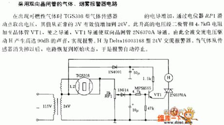
The gas-fog alarm circuit of dual-way thyristors When there is the combustible, the conductance of the TGS308 gas sensor is increasing, and it picks out the voltage with the help of potentiometer RP1, the value of the voltage is from 3V to 20V. The raised voltage is then added on transistor VT1 by the diode and the 4.7kΩ resistor, so VT1 is conducting, which makes the dual thyristor 2N6070A conducting. Because of what described above, the full-wave AC voltage pushes H to generate the sound of 90dB, fulfilling the alarm. H is the 24V AC alarm of Deltal6003168.
(View)
View full Circuit Diagram | Comments | Reading(681)
The time delay over-voltage alarm circuit of the AC regulator
Published:2011/6/26 21:50:00 Author:Borg | Keyword: time delay, over-voltage alarm, AC regulator
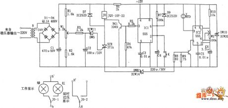
In the figure is the time delay over-voltage alarm circuit of the AC regulator. The alarm consists of the high-voltage time delay circuit, over-voltage detection and alarm circuit, output control circuit and so on. The output circuit consists of the controllable silicon SCR, relay J0 and D7. The high-voltage time-delay circuit is a time delay oscillating circuit composed of 555, R7 and C4. When the AC power supply is on, as the voltage on C4 can't mutate, the 2-pin is in a low LEV and the 555 3-pin is outputting a high LEV, which makes BG1 conducting.
(View)
View full Circuit Diagram | Comments | Reading(1807)
The voltage control non-linear function oscillator circuit
Published:2011/6/26 22:06:00 Author:Borg | Keyword: voltage control, non-linear function, oscillator
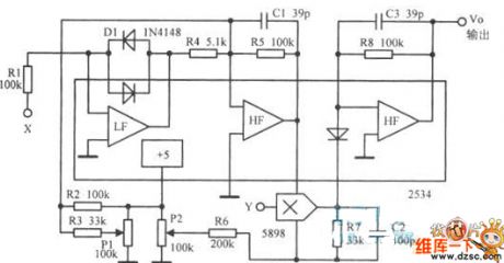
The voltage control non-linear function oscillator circuit is shown in the figure.
(View)
View full Circuit Diagram | Comments | Reading(594)
The multi-way touch stereo alarm circuit
Published:2011/6/27 20:06:00 Author:Borg | Keyword: multi-way, touch stereo alarm
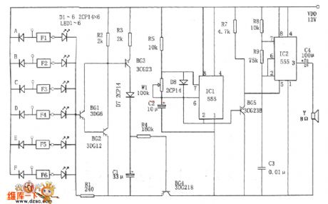
In the figure is the multi-way touch stereo alarm circuit. This circuit consists of the power supply switch circuit, stereo circuit, touch alarm display circuit and so on, which can be used to secure and monitor 6 spots. The power supply switch circuit composes of BG1~BG4, the stereo circuit consists of IC1 and IC2, the touch alarm display circuit consists of the diodes D1~D6, the phase reverser, LED1~LED6, and IC1, R5, W1 and C2 compose the non-stable multi-resonance oscillator, the oscillating frequency is f=l.44/(R5+2Rw1)C2, the regulating potentiometer W1 makes the frequency at 1Hz or so.
(View)
View full Circuit Diagram | Comments | Reading(1284)
The sound control duty alarm circuit
Published:2011/6/26 22:16:00 Author:Borg | Keyword: sound control, duty alarm
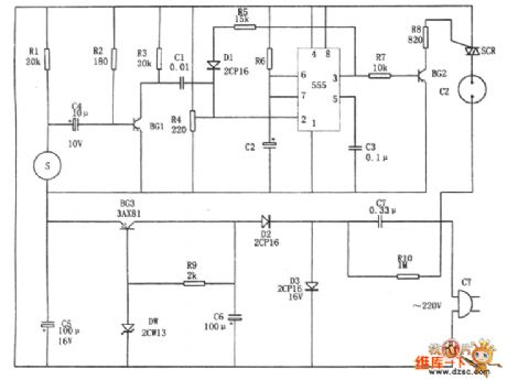
In the figure is the sound control duty alarm circuit. The alarm consists of the DC regulated power supply, timing switch circuit and sound control pulse generator. In the circuit, S is the microphone, which converts the step sound and other sounds into the electric signals, and the signals are added on the trigger terminal 2-pin of the 555 time-based circuit. 555, R6 and C2 compose a single steady trigger, the adjusting resistor R6 makes the voltage on 2-pin a little higher than 1/3VDD. The 3-pin of 555 outputs a low LEV. When there's something happening, BG2 is outputting a passive pulse of certain amplitude, which reverses 555.
(View)
View full Circuit Diagram | Comments | Reading(626)
The protection circuit diagram adopted transistor triode
Published:2011/6/24 4:08:00 Author:Nicole | Keyword: protection, transistor, triode
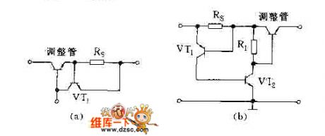
The protection circuit which adopts transistor triode, the regulator's amperage is limited by using the triode's emitter junction slot, the protection circuit's position can be setin the front or back of adjustment, it depends on the used PNP type or NPN type, in the figure, the protection circuit is made of VT1 and RS.
(View)
View full Circuit Diagram | Comments | Reading(666)
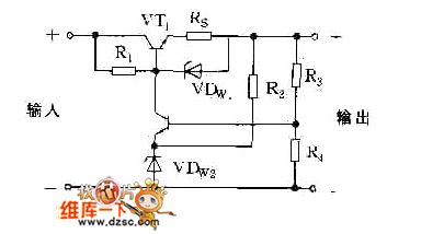
The protection circuit diagram adopted Zener diode VDW1
Published:2011/6/24 8:19:00 Author:Nicole | Keyword: protection, Zener diode
View full Circuit Diagram | Comments | Reading(646)
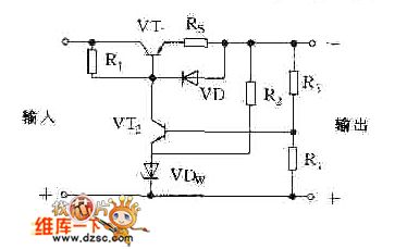
The current limiting protection circuit diagram adopted diode
Published:2011/6/24 8:21:00 Author:Nicole | Keyword: current limiting protection, diode
View full Circuit Diagram | Comments | Reading(638)
The electric touch filament lamp regulating system circuit
Published:2011/6/27 10:16:00 Author:Borg | Keyword: electric touch, filament lamp
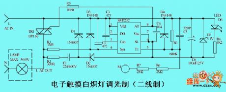
The circuit is mainly made of the special chip SM7232, with the human touch of the touch chip at point M, it controls the ON/OFF and the dimming of the filament lamp, the maximum power load of the circuit is 500W. LED would better be installed near the touch chip, which can be the indicator in the dark. Considering the human security, two resistors of R6 and R7 are adopted. (View)
View full Circuit Diagram | Comments | Reading(1262)
Simple four stages light changing switch circuit
Published:2011/6/27 2:59:00 Author:TaoXi | Keyword: Simple, four stages, light changing, switch circuit
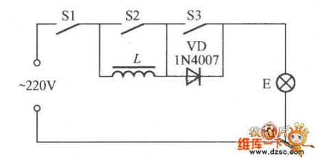
The simple four stages light changing switch circuit is as shown in the figure, it has four stages of luminance combination: when the switches S1, S2, S3 are all closing, light E is the brightest; when the switches S1 and S3 are closing, the light E is in the bright state; when the S1 and S2 are closing, and the S3 is opening, the light E is in the dark state; when the S1 is closing, the S2 and S3 are opening, the light E is in the darkest state; if S1 open, the light E will turn off. L can be used as the inductance of the 20~40W fluorescent ballast, the power of E can not exceed 60W.
(View)
View full Circuit Diagram | Comments | Reading(580)
Simple light changing stay wire switch circuit
Published:2011/6/27 3:34:00 Author:TaoXi | Keyword: Simple, light changing, stay wire, switch circuit
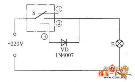
The simple light changing stay wire switch circuit is as shown in the figure, if you want to use it, you just need to pull the switch, the light will turn on; if you pull again, the light will darken; if you pull it the third time, the light will turn off, it is very convenient.
(View)
View full Circuit Diagram | Comments | Reading(707)
Lighting indication light switch circuit
Published:2011/6/27 3:56:00 Author:TaoXi | Keyword: Lighting indication, light switch circuit

The lighting indication light switch circuit is as shown in the figure, when the switch S is opening, the 220V AC current is reduced and limited by the resistance R, then it adds to the two ends of the LED with the bulb E, so the LED has power to turn on. We can find the switch at night. At this point the current which flows through E is very small, it is only 2mA, we can consider that it has no power consumption, the light will not turn on. If you close the S, the bulb E can shine normally, at this time the LED turns off. If you open S, and the LED will not shine, this means that the filament of bulb E has burned off or the power grid has cut off.
(View)
View full Circuit Diagram | Comments | Reading(659)
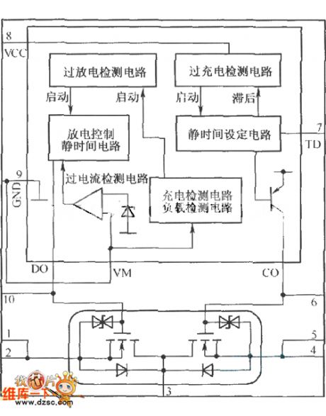
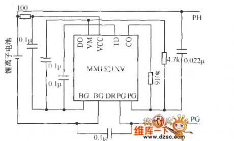
The internal structure diagram and the protection circuit of the MCP component (MMl521XV)
Published:2011/6/27 3:58:00 Author:TaoXi | Keyword: internal structure diagram, protection circuit, MCP component
View full Circuit Diagram | Comments | Reading(648)
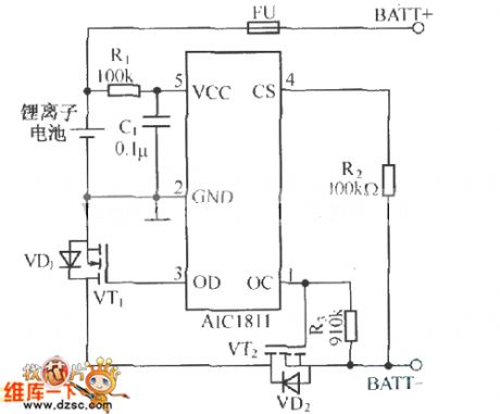
Single lithium-ion battery protection circuit composed of the AICl811
Published:2011/6/27 4:04:00 Author:TaoXi | Keyword: Single lithium-ion battery, protection circuit
View full Circuit Diagram | Comments | Reading(622)
Guangzhou Honda Odyssey anti-theft system circuit
Published:2011/6/27 4:05:00 Author:TaoXi | Keyword: Guangzhou, Honda, Odyssey, anti-theft system circuit
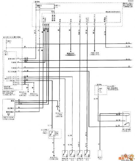
Guangzhou Honda Odyssey anti-theft system circuit:
(View)
View full Circuit Diagram | Comments | Reading(620)
TAl226NA transient state of luminance improvement integrated circuit
Published:2011/6/16 22:14:00 Author:chopper | Keyword: transient state, luminance, improvement, integrated circuit
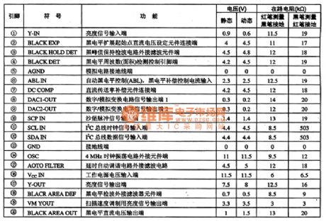
TAl226NA is a transient state of luminance improvement integrated circuit,and it is applied to various large-screen colour TVs to improve the transient state of luminance.Its function and data of pins of the integrated circuit are shown as chart 1.
(View)
View full Circuit Diagram | Comments | Reading(559)
| Pages:240/312 At 20221222223224225226227228229230231232233234235236237238239240Under 20 |
Circuit Categories
power supply circuit
Amplifier Circuit
Basic Circuit
LED and Light Circuit
Sensor Circuit
Signal Processing
Electrical Equipment Circuit
Control Circuit
Remote Control Circuit
A/D-D/A Converter Circuit
Audio Circuit
Measuring and Test Circuit
Communication Circuit
Computer-Related Circuit
555 Circuit
Automotive Circuit
Repairing Circuit