
Control Circuit
Index 238
Touch-press type SCR zero-passaging switch circuit
Published:2011/6/19 21:41:00 Author:TaoXi | Keyword: Touch-press type, SCR, zero-passaging, switch circuit
The touch-press type SCR zero-passaging switch circuit has two touch-press type switch circuit, the former is the touch-press type on-off switch, the latter is the touch-press type long delay timing switch. If you connect it with the SCR zero-passaging switch circuit, you can form the touch-press type SCR zero-passaging switch circuit. You only need to connect the output B port of this circuit with the input control port B of the SCR zero-passaging switch circuit.
(View)
View full Circuit Diagram | Comments | Reading(1168)
Touch plate relay circuit
Published:2011/6/19 21:57:00 Author:TaoXi | Keyword: Touch plate, relay circuit
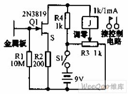
The touch plate relay circuit is as shown in the figure, when the finger touches the 2 inches sheetmetal, the induction AC signal makes the MOSFET drain current to 1.7mA, the relay gets the power to close, if you connect the capacitor to the relay coil in parallel, you can delay the release.
(View)
View full Circuit Diagram | Comments | Reading(986)
Simple light-operated street lamp circuit diagram(1)
Published:2011/6/27 21:19:00 Author:Ecco | Keyword: Simple , light-operated , street lamp
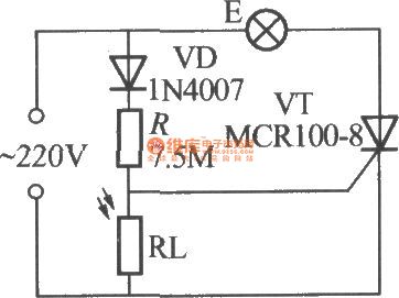
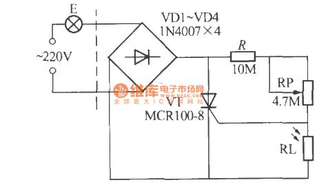
The chart shows the simple light-operated street lamp circuit which is easy to make, as long as the advent of night, lamps will be automatically lit and turned off in the daytime. The circuit has a soft start function, when night falls, the natural light is gradually weak, so the photosensitive resistor RL is larger gradually, and VT gate level is gradually increased. Therefore, the on and off atate of thyristor is a stage of micro-conduction and conduction-weak, so the light E has a soft-start process of been gradually brighten.
(View)
View full Circuit Diagram | Comments | Reading(2044)
Light control circuit diagram
Published:2011/6/27 4:16:00 Author:Ecco | Keyword: Light control
View full Circuit Diagram | Comments | Reading(1218)
Simple light-operated street lamp circuit diagram(2)
Published:2011/6/27 21:24:00 Author:Ecco | Keyword: Simple, light-operated , street lamp
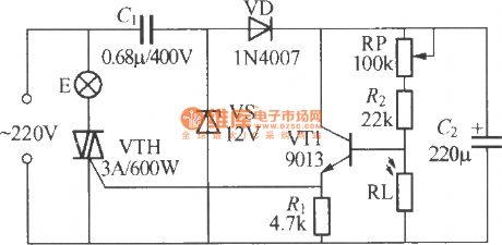
The chart shows the simple light-operated street lamp circuit, which is simple, easy to use. The current flowing lamp is the full-wave AC current, so the lamp light is in a normal state. Its brightness is much more than half-voltage power supply, and electronic circuit and light bulbs use two-wire connection to simplify installation.
(View)
View full Circuit Diagram | Comments | Reading(842)
Simple light-operated street lamp circuit diagram(3)
Published:2011/6/27 21:57:00 Author:Ecco | Keyword: Simple , light-operated , street lamp
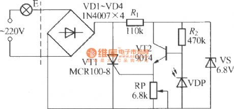
VDP is the photodiode and it has low resistance in the day, and resistance ≤ 1kΩ, then transistor VT2 is turned off, then thyristor VT1 is in the off-state as the gate has no trigger current, and E can not be lit. In the night, VL shows a high resistance as no light exposure, and the resistance ≥ 100kΩ, then VT2 is turned on, and the emitter can output positive trigger current whcih is flowing through the gate of VT1, the opening of VT1, then E is lit. Adjusting RP can turn on EL when the lighting circuit needs to be lit. The regulator VS is set in the circuit to make it work more stable and reliable.
(View)
View full Circuit Diagram | Comments | Reading(1619)
Simple light-operated street lamp circuit diagram(4)
Published:2011/6/27 22:06:00 Author:Ecco | Keyword: Simple , light-operated , street lamp
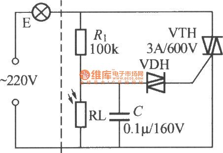
The chart shows the simple light-operated street lamp circuit which is made by two-way thyristor, and it also uses two-wire connection, so installation is relatively simple. During the day, photo-resistor RL the low resistance due to exposure of natural light. The circuit has a soft-start process, which can help to extend the lamp life. Increasing or decreasing the value of R1 can change the sensitivity of light control circuit, but generally it does not have to adjust. VDH can use the bi-directional trigger diode with the turning voltage in 20 ~ 40V, such as 2CTS, DB3 types.
(View)
View full Circuit Diagram | Comments | Reading(1516)
Simple light-operated street lamp circuit diagram(5)
Published:2011/6/27 22:08:00 Author:Ecco | Keyword: Simple , light-operated , street lamp
The chart shows the simple light-operated street lamp circuit which is made by two-way thyristor, and it consists of three major componentsof thyristor major loop, light control switches and power circuit.
(View)
View full Circuit Diagram | Comments | Reading(892)
Simple light-operated street lamp circuit diagram(7)
Published:2011/6/27 20:42:00 Author:Ecco | Keyword: Simple , light-operated , street lamp
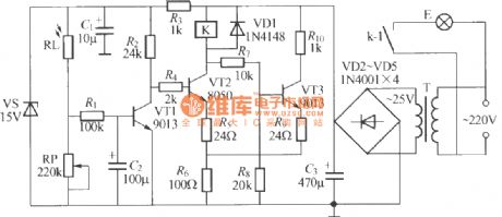
The chart shows the automatic light-operated street lamp circuit with good performance, and it has high sensitivity, stable performance and good robustness. In the figure, R1, C1 form the interference pulse absorption circuit to prevent short-term light exposure at night or circuit malfunction caused by leaves, flying paper and short-term shelter and other factors in the day. T uses 220V/25V, 25VA high-quality power transformer,which requires no-heating for a long time. K can use JQX-13F, DC24V power electromagnetic relay with the contact capacity in AC220V, 15A.
(View)
View full Circuit Diagram | Comments | Reading(625)
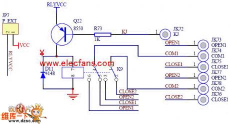
Relay control circuit diagram
Published:2011/6/27 3:52:00 Author:Ecco | Keyword: Relay , control
View full Circuit Diagram | Comments | Reading(604)
RF input receiver with bandpass filter switch circuit
Published:2011/6/21 0:05:00 Author:John | Keyword: RF input receiver, bandpass filter, switch
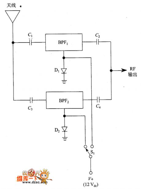
RF input receiver with bandpass filter switch circuit is shown. (View)
View full Circuit Diagram | Comments | Reading(640)
PIN diode with band-pass filter switch circuit
Published:2011/6/19 10:56:00 Author:John | Keyword: diode, band-pass filter, switch
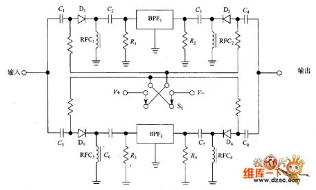
The picture shows how to choose a variety of band-pass filters in the circuit, for which only the DC signal lines are between the panel and the circuit. Input end and output end shown in the figure all have PIN diode. The PIN diodes are all powered by +12 V selected by the switch S1 or-12V DC power supply. When the switch is in the position shown, +12 V powers filter 1’s switch and the filter 1 works. When the switch is in the opposite position, the other filters work. This method can also be used for receiver’s front-end or local oscillator in order that different frequency bands can be selected for different LC components.
figure: PIN diode with band-pass filter switch circuit (View)
View full Circuit Diagram | Comments | Reading(2161)
PIN diode switch circuit
Published:2011/6/19 10:48:00 Author:John | Keyword: diode, switch
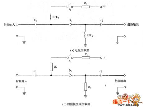
In the circuit shown in Figure (a), the diode Dy and the signal line are used in series. When the diode conducts, the signal path is with low resistance. When the diode closes, it presents a high resistance (so as to achieve the switching function). When the switch S opens, the diode is not biased. The circuit has been disconnected because of the diode’s impedance. When S closes, the diode is forward biased and the resistance of signal channel is very low. The impedance ratio by the state of opening and closing is a measure of isolation for the circuit.
(View)
View full Circuit Diagram | Comments | Reading(835)
Various IF filters circuit
Published:2011/6/17 9:45:00 Author:John | Keyword: IF filter
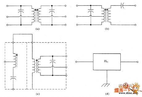
Most of the gain and selectivity of superheterodyne radio receivers are provided by the intermediate frequency (IF) amplifier. Therefore, it is a amplifier with high-gain and narrow bandwidth. IF power gain is typically between 60 dB and 120dB. Scuh range depends on the specific design for the receiver. Usually it has a much narrower bandwidth than the RF amplifier. For example, SSB receiver’s bandwidth is 2.8kHz and the CW receiver’s bandwidth is 500Hz. IF amplifier's role is to provide gain and selectivity for the receiver. The selective parts are achieved by a variety of filters.
(View)
View full Circuit Diagram | Comments | Reading(592)
Touch switch circuit
Published:2011/6/19 22:18:00 Author:TaoXi | Keyword: Touch switch
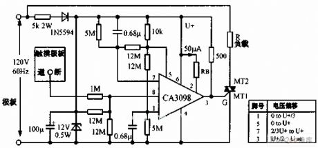
The touch switch circuit is as shown in the figure, if you use the finger to touch the pole plate, the pole plate inputs the small AC signal at the pin-8 of the double input port high precision level detector CA3089 to produce the voltage which is higher than the benchmark. In the integrated circuit, this voltage turns the memory trigger, the pin-5 has the high level. The voltage of pin-7 increases to U exponentially in 10 seconds. The 10 seconds is the maximum delay time, the long time touch can makes the circuit to oscillate between the two states of the on-off until the finger removes. The short time touch can make to load to get power, if you touch again, the load will cut off the power.
(View)
View full Circuit Diagram | Comments | Reading(805)
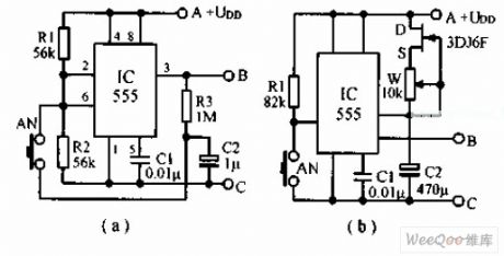
Touch type SCR zero-passaging switch cicuit
Published:2011/6/19 22:26:00 Author:TaoXi | Keyword: Touch type, SCR, zero-passaging, switch cicuit
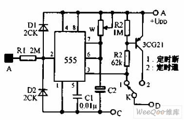
The touch type SCR zero-passaging switch cicuit is as shown in the figure. This circuit is designed as the touch type timer. If you connect the touch type timer with the SCR zero-passaging switch, you can form the touch type SCR zero-passaging switch cicuit. When the human body touches the sheetmetal A, the induction signal conducts the 555. WHen the K is in the 1 position, the function is to control the outage of the equipment when the preset time is up; if K is in the 2 position, the function is to turn on the power of the equipment when the preset time is up.
(View)
View full Circuit Diagram | Comments | Reading(643)
One hour timer circuit with the end switch
Published:2011/6/19 22:45:00 Author:TaoXi | Keyword: One hour, timer, end switch
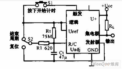
The one hour timer circuit with the end switch uses the LM122 timer and the hand control switch, the LM122 timer and the hand control switch can form the one hour timer which has the start, reset and stop functions. Once the timing begins, the S1 will not play any functions. You can pull the S2 up to finish the rated cycle, the output state will change; if you pull the S2 down, the timing capacitor voltage will be back to 0V, the output state will not change, it releases the S2 to start the new timing cycle.
(View)
View full Circuit Diagram | Comments | Reading(899)
Four hours order timer circuit
Published:2011/6/20 3:39:00 Author:TaoXi | Keyword: Four hours, order timer
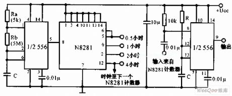
The four hours order timer circuit uses the N8281 distributor network between the two timers of the double timer 556, it does not use the big volume low leakage current capacitor, so it has the long delay time. The first timer forms the oscillator, the output adds to the output which is produced by the N frequency division network with the N/f cycle, it triggers the monostable circuit which is composed of the second timer. The delay time depends on the delay output time of the distributor. You can cascade some distributors to make the delay time to a few days or weeks.
(View)
View full Circuit Diagram | Comments | Reading(1054)
Ten hours delay circuit
Published:2011/6/20 3:50:00 Author:TaoXi | Keyword: Ten hours, delay circuit
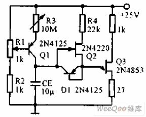
The ten hours delay circuit is as shown in the figure. The constant current source is composed of the transistor Q1 and the R1, R2, R3, the charge current can be adjusted to a few nA. The source follower is composed of Q2, the output is connected with the emitter of the single junction transistor Q3. The transistor which is connected into the diode supplies the low resistance discharging pathway to the timing capacitance. The delay time linearly changes with R3.
(View)
View full Circuit Diagram | Comments | Reading(859)
80V effective value analog switch circuit
Published:2011/6/20 7:31:00 Author:TaoXi | Keyword: 80V, effective value, analog switch
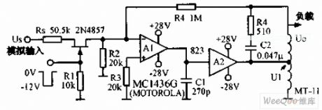
The 80V effective value analog switch circuit is as shown in the figure. In this circuit, the A1 is the operational amplifier MC1436G, A2 is the 823 type power operational amplifier, T1 is the small transformer MT11. The feedback circuit stabilizes the output signal to reduce the influence of the circuit parameters changing. The AC input signal which is changed in the range of ±10V can be turned on and off by the FET gate's -12V voltage, when the gate voltage is 0V, the switch turns on and the voltage is amplified and output by the amplification transformer. This circuit can be used in the digital same-frequency converter.
(View)
View full Circuit Diagram | Comments | Reading(673)
| Pages:238/312 At 20221222223224225226227228229230231232233234235236237238239240Under 20 |
Circuit Categories
power supply circuit
Amplifier Circuit
Basic Circuit
LED and Light Circuit
Sensor Circuit
Signal Processing
Electrical Equipment Circuit
Control Circuit
Remote Control Circuit
A/D-D/A Converter Circuit
Audio Circuit
Measuring and Test Circuit
Communication Circuit
Computer-Related Circuit
555 Circuit
Automotive Circuit
Repairing Circuit