
Control Circuit
Index 227
The low-speed single steady circuit
Published:2011/7/4 4:32:00 Author:Seven | Keyword: low-speed, single steady circuit

View full Circuit Diagram | Comments | Reading(583)
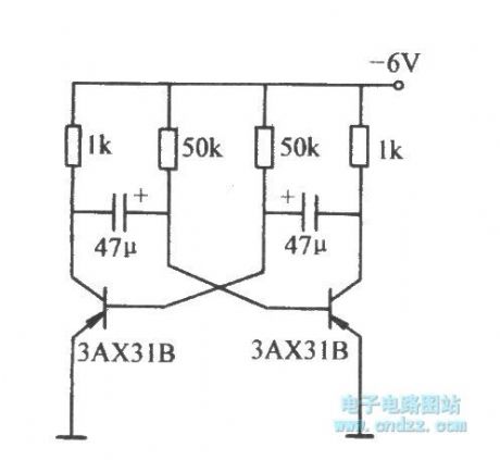
The low-frequency astable circuit
Published:2011/7/4 4:33:00 Author:Seven | Keyword: low-frequency, astable circuit
View full Circuit Diagram | Comments | Reading(738)
The key switch circuit
Published:2011/7/4 4:34:00 Author:Seven | Keyword: key switch
View full Circuit Diagram | Comments | Reading(710)
The balcony burglarproof lamp
Published:2011/7/4 5:56:00 Author:Borg | Keyword: balcony burglarproof lamp
View full Circuit Diagram | Comments | Reading(578)
The cultural relic security alarm circuit of ND-2
Published:2011/7/4 19:42:00 Author:Borg | Keyword: cultural relic, security alarm
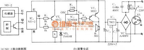
The circuit is shown in Figure (b), which consists of the vibrating sensor, relay control circuit, alarm sound generating circuit, audio power amplifier circuit and AC step-down rectifier circuit, etc. It can be used in situations of the precious object security, storeroom, safe locker, vehicle and door/window anti-burglary, etc. ND-2 is a all-direction vibrating sensing module, in figure (a) is its function frame diagram. (View)
View full Circuit Diagram | Comments | Reading(611)
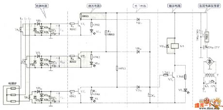
The water boiling alarm circuit
Published:2011/7/4 19:52:00 Author:Borg | Keyword: water boiling alarm
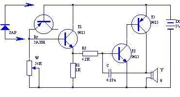
This water boiling alarm circuit consists of 4 triodes, whose circuit is shown in the figure. In the figure, the transistors T2 and T3, resistor R2 and capacitor C,etc, compose the audio oscillator, the audio signal is output from the loudspeaker. The transistor T1, resistors R1 and W, the transistor knot be and Rt, etc, compose a switch circuit as the switch of the oscillator. Rt is the temperature sensing element, which is equal to the bias resistor of T1. Usually, Rt is reversely blocked, T1 is also blocked; when the temperature is rising up, the reversal resistance of Rt is falling down, the current leakage is rising up.
(View)
View full Circuit Diagram | Comments | Reading(870)
The gas leakage alarm
Published:2011/7/4 6:14:00 Author:Borg | Keyword: gas leakage alarm

The gas sensor can form a gas leakage wireless remote control alarm, when the gas leakage is over the content of the safety standard, the sensor is outputting a detecting signal, and the wireless emitter circuit is emitting alarm signal after the signal is amplified and processed. In the figure is the gas leakage wireless remote control alarm which consists of the gas sensor(QM-N10), when the gas leakage is over the regulated standard, the relay will pull in and get the working power supply of the emitter circuit through. The emitter circuit of the alarm has not been drawn in the figure.
(View)
View full Circuit Diagram | Comments | Reading(1290)
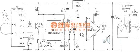
The radar monitor language alarm
Published:2011/7/4 6:02:00 Author:Borg | Keyword: radar monitor, language alarm
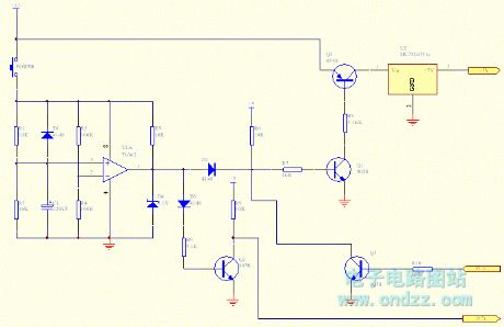
The circuit consists of the microwave sensing part TWH9248/TWH9249, single steady time delay circuit, language alarm circuit, FM emitter circuit and power supply circuit,etc.
(View)
View full Circuit Diagram | Comments | Reading(728)
The Smoking Ban and Fire Warning Board Circuit
Published:2011/7/4 6:20:00 Author:Borg | Keyword: Smoking Ban, Fire Warning
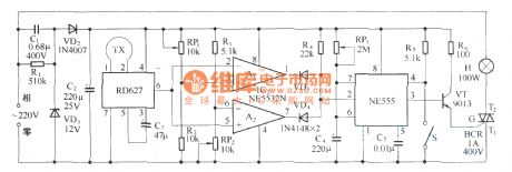
When someone walks past the valid range of the warning board, this circuit will make the sound of twang```no smoking, no fire . (View)
View full Circuit Diagram | Comments | Reading(761)
sound and light of resistance furnace alarming circuit
Published:2011/7/4 0:17:00 Author:John | Keyword: resistance furnace
View full Circuit Diagram | Comments | Reading(693)
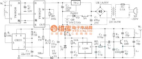
Microwave radar automatic lamp circuit(4)(TWH9250)
Published:2011/7/1 1:14:00 Author:zj | Keyword: Microwave radar automatic lamp circuit(4)(TWH9250), TWH9250, LM7812
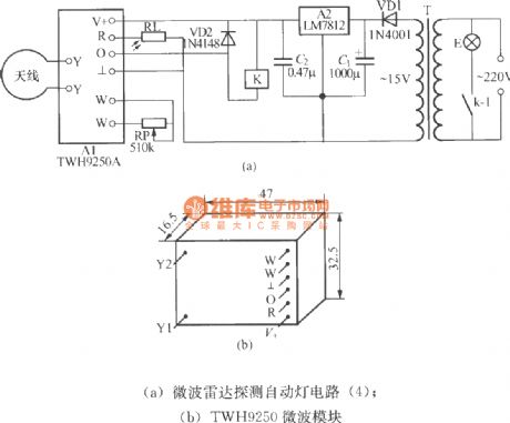
(a) Microwave radar automatic lamp circuit(4)
(b) TWH9250 microwave module
As the diagram shows,the annular antenna can use Φ1~3mm enameled wire to bend to circle andto connect to X,Y ports of the module. (View)
View full Circuit Diagram | Comments | Reading(743)
The single key 555 dual steady switch circuit
Published:2011/7/3 20:48:00 Author:Borg | Keyword: single key, dual steady switch
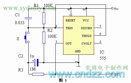
In figure 1 is the circuit. When the circuit gets power, C1 makes 6-pin of IC(555) acquire a positive pulse, the 3-pin is outputting a low LEV, at the moment, there is no voltage on C2. By pressing the key of S, the 0 LEV is working on 2-pin of the IC, 3-pin is reversed in a high LEV, C2 is charged by R3. After S is released, C2 is charged to Vcc, both the 2-pin and 6-pin are offset to 1/2Vcc by R1 and R2, the high LEV of 3-pin remains the same. By pressing S again, the voltage on C2 makes the voltage on 6-pin of the IC higher than 2/3Vcc, and 3-pin is reversed in a low LEV. (View)
View full Circuit Diagram | Comments | Reading(1452)
The single key switch circuit
Published:2011/7/3 20:51:00 Author:Borg | Keyword: single key
View full Circuit Diagram | Comments | Reading(529)
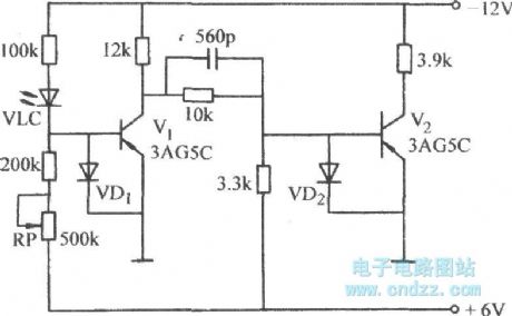
The high speed switch circuit with clamping diodes
Published:2011/7/3 21:19:00 Author:Borg | Keyword: high speed switch, clamping diodes
View full Circuit Diagram | Comments | Reading(749)
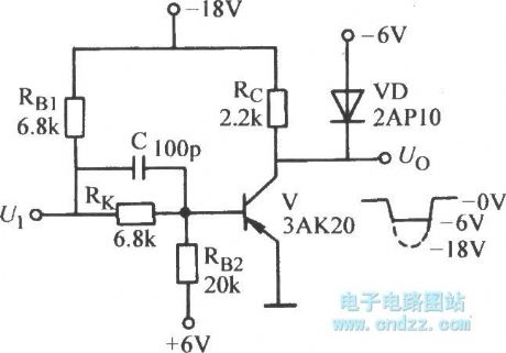
The two stage phase inverter circuit with diode protection
Published:2011/7/3 20:54:00 Author:Borg | Keyword: phase inverter, diode protection
View full Circuit Diagram | Comments | Reading(759)
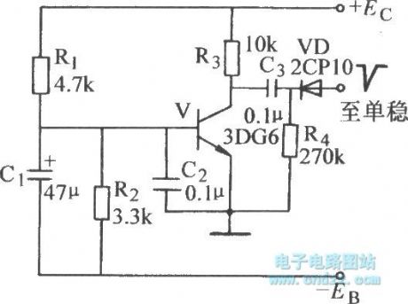
The starting circuit of single steady state
Published:2011/7/3 20:56:00 Author:Borg | Keyword: starting circuit, single steady state
View full Circuit Diagram | Comments | Reading(648)
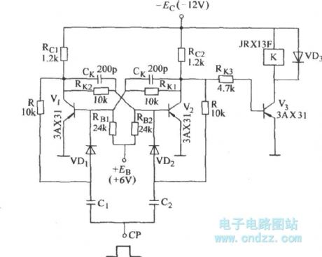
The dual steady circuit with relays
Published:2011/7/3 20:57:00 Author:Borg | Keyword: steady circuit
View full Circuit Diagram | Comments | Reading(605)
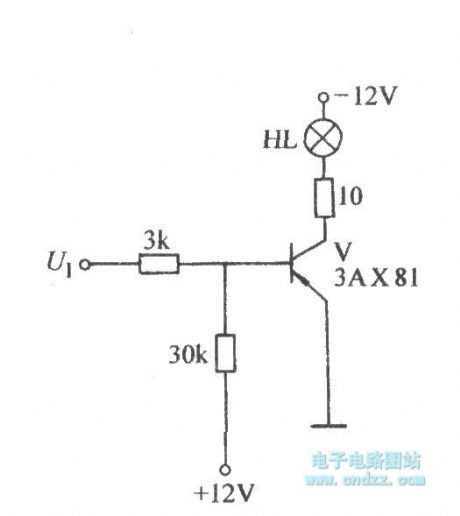
The circuit of the phase inverter with lamps
Published:2011/7/3 20:59:00 Author:Borg | Keyword: phase inverter
View full Circuit Diagram | Comments | Reading(648)
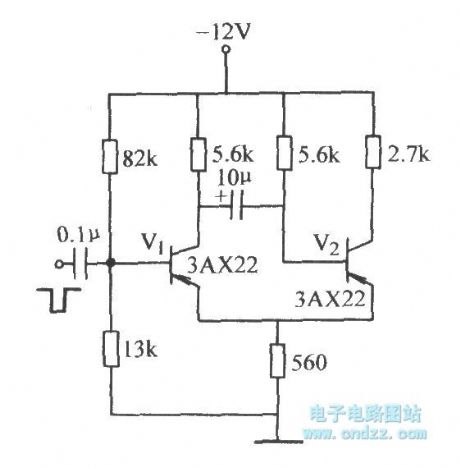
The single steady circuit with trigger signals on the basic pole of blanking tubes
Published:2011/7/3 21:18:00 Author:Borg | Keyword: single steady circuit, trigger signals, basic pole
View full Circuit Diagram | Comments | Reading(619)
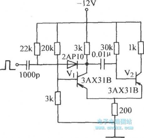
The single steady circuit with trigger signals on the basic pole of the conducting pipe
Published:2011/7/3 22:01:00 Author:Borg | Keyword: single steady circuit, trigger signals, conducting pipe
View full Circuit Diagram | Comments | Reading(573)
| Pages:227/312 At 20221222223224225226227228229230231232233234235236237238239240Under 20 |
Circuit Categories
power supply circuit
Amplifier Circuit
Basic Circuit
LED and Light Circuit
Sensor Circuit
Signal Processing
Electrical Equipment Circuit
Control Circuit
Remote Control Circuit
A/D-D/A Converter Circuit
Audio Circuit
Measuring and Test Circuit
Communication Circuit
Computer-Related Circuit
555 Circuit
Automotive Circuit
Repairing Circuit