
Control Circuit
Index 232
Motor protector 1
Published:2011/6/27 4:44:00 Author:Nicole | Keyword: Motor, protector
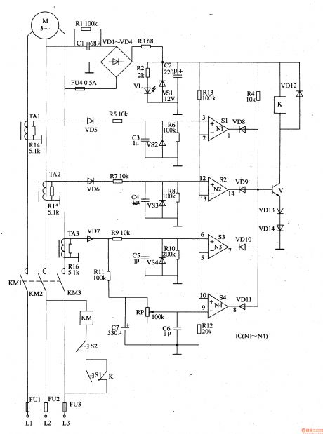
The power supply circuit is composed of capacitors C1, C2, resistors R1-R3, rectifier diodes VD1-VD4, Zener diode VS1 and power supply indication LED VL.
The current detection circuit is made of current transformer TAl-TA3, resistors R5-R11, R14-R16, diodes VD5-VD7, Zener diode VS2-VS4, potentiometer RP, capacitors C3-C7.
The protection control circuit consists of operation amplifier integrated circuit IC(N1-N4), resistors R4, R12, R13, diodes VD8-VDl4, transistor V, relay K, AC contactor KM and starting button S1, stopping button S2.
(View)
View full Circuit Diagram | Comments | Reading(786)
Loom saves electricity controller 6
Published:2011/6/29 22:16:00 Author:Nicole | Keyword: loom, saves electricity controller
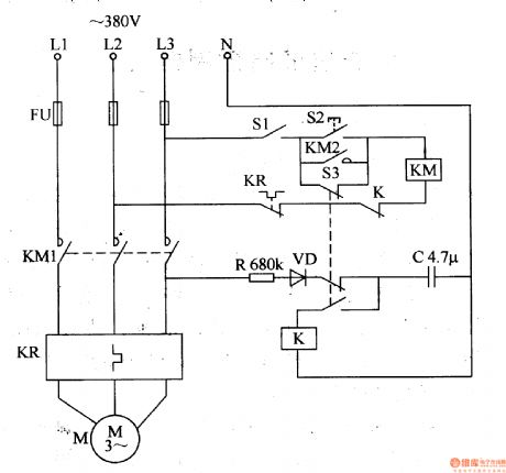
The loom saves electricity controller circuit is composed of control switch S1, starter button S2, AC contactor KM, heat relay KP, relay K, resistor R, capacitor C, rectifier diode VD and microswitch S3, it is shown in the figure 8-22.
The control switch S1 is turned on, the starter button S2 is pressed, AC contactor KM is connected and pulled in, it is self-lock, the motor M is electrifying and running. The loom's machine open and shut down handle is set in start-up position, the microswitch S3's two groups normally closed contacts are turned on, the normally open contact cuts off.
(View)
View full Circuit Diagram | Comments | Reading(826)
Control voltage phase shifting trigger circuit
Published:2011/6/27 7:20:00 Author:Christina | Keyword: Control voltage, phase shifting, trigger circuit
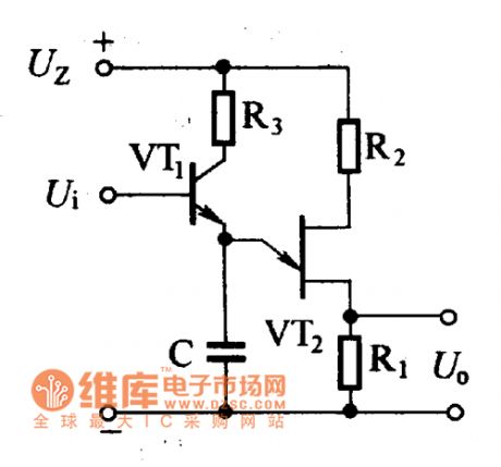
As the figure shows, this circuit uses the semiconductor transistor instead of the charging resistance R, and this circuit adds the control voltage Vi on the base electrode of the transistor, when the Ui changes, the collector electrode current IC of the VT1 will change too. When the IC increases, the trigger pulse moves forward; when the IC decreases, the trigger pulse moves backward to achieve the purpose of the phase shifting.
Control voltage phase shifting trigger circuit (View)
View full Circuit Diagram | Comments | Reading(632)
Complementary oscillator trigger circuit
Published:2011/6/27 7:26:00 Author:Christina | Keyword: Complementary oscillator, trigger circuit
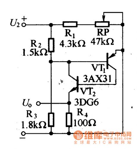
The circuit is as shown in the figure. The positive feedback loop is composed of the VT1 and VT2 to produce the self-excited oscillation triggering pulse, you can change the cycle of the self-excited oscillation triggering pulse by adjusting RP, and this circuit plays the role of phase shifting.
Complementary oscillator trigger circuit (View)
View full Circuit Diagram | Comments | Reading(634)
Neon light trigger circuit
Published:2011/6/27 7:51:00 Author:Christina | Keyword: Neon light, trigger circuit
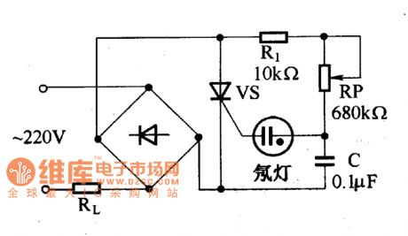
The circuit is as shown in the figure, it is composed of the R1, RP, C and the neon light. The general neon light can puncture the conduction with the voltage of 60 to 90V, we can form the relaxation oscillator by using this feature, and this relaxation oscillator produces the pulse to trigger the thyristor to adjust the voltage. When the voltage of the capacitor is charged to the neon light's striking voltage, the neon light is punctured, the voltage of capacitance C discharges to the control electrode of the thyristor, and the trigger thyristor conducts. After the voltage of capacitance C discharges, the neon light turns off and the power recharges the C. So we can get a series of trigger pulses.
Neon light trigger circuit (View)
View full Circuit Diagram | Comments | Reading(765)
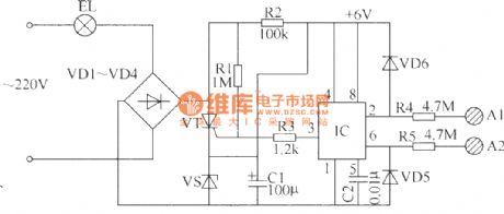
Smoke alarm circuit
Published:2011/6/28 2:58:00 Author:Christina | Keyword: Smoke, alarm
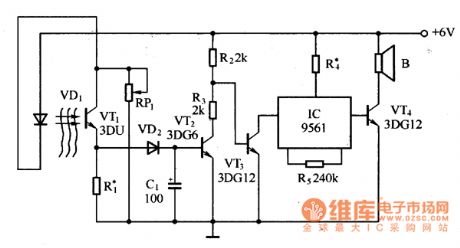
The smoke alarm circuit is composed of the infrared light tube, the series feedback photosensitive circuit (composed of the phototransistor), the semiconductor tube switch circuit and the integrated alarm circuit, as the figure 8 shows. When the monitored environment has no smoke, the infrared light-emitting diode VD1 lights with the pre-tuned initial current. This infrared light is received by the photosensitive transistor VT1 to reduce the resistance of VT1 amd increase the current of VD1 and VT1, so the luminous intensity of the infrared light-emitting diode VD2 increases accordingly.
Figure: Smoke alarm circuit (View)
View full Circuit Diagram | Comments | Reading(732)
Loom saves electricity controller 5
Published:2011/6/29 22:05:00 Author:Nicole | Keyword: loom, saves electricity controller
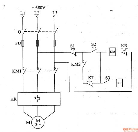
The loom saves electricity controller circuit is composed of knife switch Q, fuse FU, stop button S1, starter button S2, microswitch S3, time relay KT, AC contactor KM, heat relay KP and motor M, it is shown in the figure 8-21.
The knife switch Q is connected, starter button S2 is pressed, AC contactor KM is turned on and pulled in, motor M starts running. When the machine open and shut down handle is in start-up position, microswitch S3 is in off state, time relay KT is in release state.
(View)
View full Circuit Diagram | Comments | Reading(662)
Infrared ray alarm circuit
Published:2011/6/30 3:38:00 Author:Christina | Keyword: Infrared ray, alarm
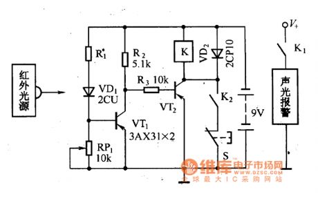
The infrared ray alarm circuit is as shown in the figure. It is composed of the light source, the receiver and the sound and light alarm circuit. There is the infrared receiver in a certain distance from the infrared light source, so there is an invisible infrared cordon between the infrared light source and the receiver.
When no one keeps out the infrared ray, the infrared ray irradiates on the photosensitive diode VD1 directly, so the photosensitive diode's resistance becomes smaller to conduct the VT1, the VT2 is in the cut-off state, the relay K which is connected with the collector VT2 will not work, the contact point K1 opens, so the sound and light alarm system has no power voltage to work.
Figure The Infrared ray alarm circuit (View)
View full Circuit Diagram | Comments | Reading(746)
Loom saves electricity controller 4
Published:2011/6/29 21:55:00 Author:Nicole | Keyword: loom, saves electricity controller
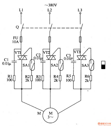
The loom saves electricity controller circuit is composed of knife switch Q, fuse FU, transistors VT1-VT3, resistors R1-R6, capacitors C1-C3, spring tubes SA1-SA2 and motor M, it is shown in the figure 8-20.
Knife switch Q is turned on, the loom's machine open and shut down handle is pushed blak of the start-up position, under the magneticaction of machine open and shut down handle's permanent magnet, the spring tubes SA1-SA2's control contact is connected, VT1-VT3 are triggered and turned on, motor M runs.
The sensitivity of V1-V3 trigger can be changed by adjusting R2, R4 and R6.
(View)
View full Circuit Diagram | Comments | Reading(656)
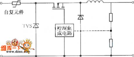
Simple and practical TV lightning prevention protection circuit
Published:2011/6/24 22:25:00 Author:TaoXi | Keyword: Simple, practical, TV, lightning prevention, protection circuit
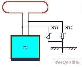
The application circuit of this device is as shown in the figure. When you are watching TV in the thunderstorm day, the thunder can damage the TV through two approaches: one is through the outdoor TV antenna; another is through the power line of TV. The former often damages the high frequency head, the latter often damages the power supply circuit of the line field output circuit. We can add the voltage dependent resistor on the outdoor antenna to prevent this consequence, the voltage dependent resistor needs to be connected with the ground. The application circuit connection method of the power protection part is as shown in figure 8.
(View)
View full Circuit Diagram | Comments | Reading(670)
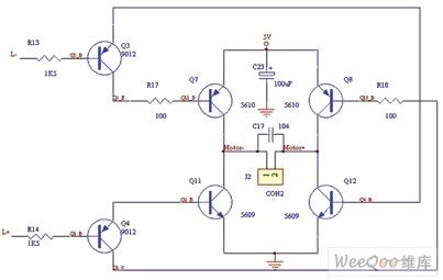
Left motor control circuit
Published:2011/6/18 21:59:00 Author:Nancy | Keyword: left motor
View full Circuit Diagram | Comments | Reading(581)
Dual-tone phone 160,168 controller circuit
Published:2011/6/29 2:28:00 Author:Fiona | Keyword: Dual-tone phone, controller
Dual-tone phone 160,168 controller circuit is shown as below,the function of this controller is the same with the controller's.The two controllers' basic principle is:add a homemade electronic switch between telephone and switchboard,only the user who officially calls 160,168 information desk can make the electronic switch be connected.
(View)
View full Circuit Diagram | Comments | Reading(772)
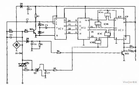
The auto open/close curtain controller circuit
Published:2011/6/30 3:31:00 Author:Seven | Keyword: curtain controller
This controller can recognize the brightness in the room automatically, which can control the curtain and make the natural light in the optimum state. In figure 1, the LDR RD and the time-based circuit 5G1555 compose the brightness recognition sector. The LDR RD receives the natural light and its resistance changes, which is set as RD1, at the moment, RD1 is falling down. The elements and their parameters are shown as follows: BG1:3DG12,BG2:3CG14,BG3:3DG12,BG4:3DG12B。D1~D3:2CP,D4~D7:2CP14,DW:2CW22C/100mA/7.5V。W1、W2:100K,RD:the LDR of the 625 type.
(View)
View full Circuit Diagram | Comments | Reading(1678)
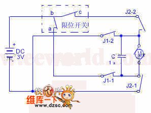
The self-made fast hand drier circuit
Published:2011/6/30 3:43:00 Author:Seven | Keyword: fast hand drier
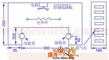
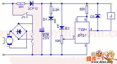
45. The self-made fast hand drier circuitThe drier will blow out warm air if the washed hand is below it, and when the hand becomes dry, it will stop automatically, see as figure 2. When there is light, the 1-pin of the IC is in a low LEV, TWH8751 is blocked, J is power-off, J1-1 is broken down. When the hand is blocking the light, D2 is in a high resistance, the 2-pin of IC is in a low LEV, so the output terminal of IC is conducting, J1-1 is passable, the heating wire and motor get power, so the warm air is blown out. The power supply of the control wire is stepped down and rectified by the 36K resistor and 2CP12, then the voltage of 18V or so is acquired.
(View)
View full Circuit Diagram | Comments | Reading(703)
The CW168 new flash alarm integrated circuit
Published:2011/6/30 4:40:00 Author:Seven | Keyword: flash alarm, integrated circuit
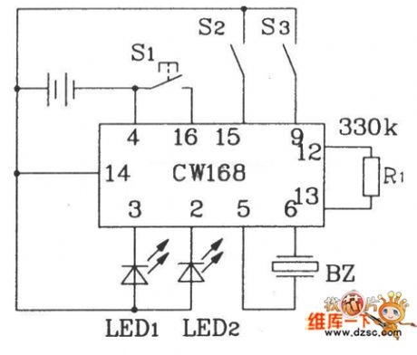
R1 is the external oscillating circuit of the internal oscillator, by changing the resistance of R1, the oscillating frequency of the oscillator inside IC can be changed, when R1=330kΩ, the IC is outputting the 4Hz flashing frequency, and the IC stops working in 16s after it is triggered for a single time. To strength the sound effect, a power triode can be connected with the output terminal, which makes the output drive the loudspeaker. Besides, it can also be connected with all kinds of control circuits to trigger CW168, so the self-control is fulfilled.
(View)
View full Circuit Diagram | Comments | Reading(601)
The typical CLA protection circuit
Published:2011/6/30 19:13:00 Author:TaoXi | Keyword: typical, CLA, protection circuit
Because the changeful car environment and to supply power for all kinds of precision electronic equipments, so the CLA needs to work in wide range of temperature and charging conditions. So the CLA always appears the short circuit fault and the fuse burning case. Generally, these cases are caused by the overcurrent, the charger circuit fault or the reverse charging. You can connect the over current protection device with the CLA input port to prevent the damage that is caused by the faults. The specific protection requirements of this device are decided by the terminal equipment's load current and the fault sensitivity of the CLA power conversion circuit.
(View)
View full Circuit Diagram | Comments | Reading(691)
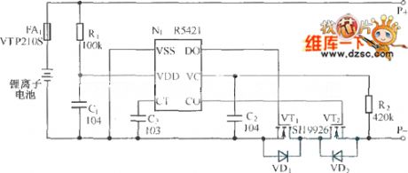
Lithium ion battery charging and discharging protection circuit
Published:2011/6/30 19:15:00 Author:TaoXi | Keyword: Lithium ion battery, charging, discharging, protection circuit
View full Circuit Diagram | Comments | Reading(793)
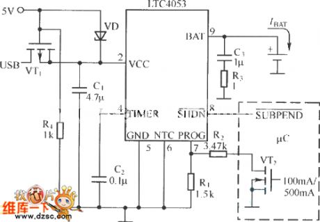
Practical USB interface Lithium ion battery charging and discharging protection circuit
Published:2011/6/30 19:16:00 Author:TaoXi | Keyword: Practical, USB, interface, Lithium ion battery, charging, discharging, protection circuit
View full Circuit Diagram | Comments | Reading(660)
The electric switch circuit of touch type (5)
Published:2011/6/30 5:27:00 Author:Seven | Keyword: electric switch, touch type
The electric switch circuit of touch type in the following introduction is in 2-line connection, which can easily replace the ordinary mechanical switch. The circuit consists of the time-based integrated circuit IC(NE555), thyristor VT, rectifying diodes VD1 and VD4, regulated diode VS and so on.
Elements selection. R2 is chosen as the 1/2W carbon film resistor, and the other resistors can be 1/4W carbon film resistor. C1 can be the aluminium electrolytic capacitor with the withstand voltage higher than 16V, C2 can be the ordinary dacron capacitor. All of VD1~VD4 are chosen as the 1N4007 rectifier diode. (View)
View full Circuit Diagram | Comments | Reading(777)
The electric switch circuit of touch type (1)
Published:2011/6/30 5:13:00 Author:Seven | Keyword: electric switch, touch type
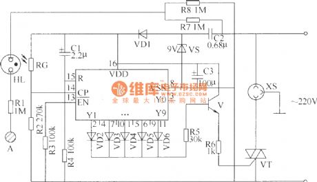
The following is to introduce a switch circuit of touch type which is made of CD4017 digital integrated circuit, thyristors and so on, when the hand touches the control pole, the electric switch will take action (ON or OFF) once, which has the same functions as ordinary mechanical switch, and it can be used to control the lighting lamp, ventilator and so on.This switch circuit consists of the power supply circuit, touching control input circuit, counter circuit and the control executing circuit.
Elements selection:R1~R8 can be chosen as the 1/4W carbon film resistor or metal film resistor. (View)
View full Circuit Diagram | Comments | Reading(701)
| Pages:232/312 At 20221222223224225226227228229230231232233234235236237238239240Under 20 |
Circuit Categories
power supply circuit
Amplifier Circuit
Basic Circuit
LED and Light Circuit
Sensor Circuit
Signal Processing
Electrical Equipment Circuit
Control Circuit
Remote Control Circuit
A/D-D/A Converter Circuit
Audio Circuit
Measuring and Test Circuit
Communication Circuit
Computer-Related Circuit
555 Circuit
Automotive Circuit
Repairing Circuit