
Control Circuit
Index 230
The ceiling lamp control switch circuit (6)
Published:2011/7/3 0:36:00 Author:Borg | Keyword: ceiling lamp, control switch
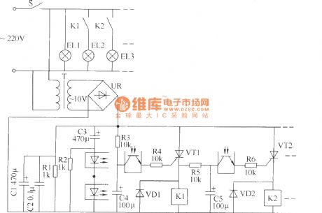
The ceiling lamp control switch circuit consists of the power supply circuit and the control circuit, see as the figure.
Element selection R1 is the 1/2W metal film resistor, R2~R6 are the 1/4W metal film resistors or carbon film resistor; C1 and C3~C5 are all made of the the aluminum electrolytic resistor whose withstand voltage is 16V; C2 is the monolithic capacitor. VD1 and VD2 are both made of the 1N4007 silicon diode. UR is the rectifier bridge of 1A and 50V. VT1 and VT2 are both the MCR100-6 thyristor. K1 and K2 are both the 9V DC relay of JZC-23F. (View)
View full Circuit Diagram | Comments | Reading(644)
The ceiling lamp control switch circuit (2)
Published:2011/7/3 6:43:00 Author:Borg | Keyword: ceiling lamp, control switch
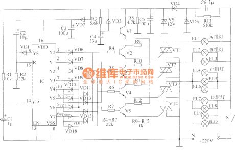
The circuit control switch that is going to be introduced here can be used to control the ceiling lamps(or fancy lamps), and it can make the ceiling lamps indicate 8 lighting states by controlling the closing times of the switches of former lights. The circuit consists of the power supply, counting/pulse distributor and the control circuit, see as the figure.
Element selection All of R1~R12 are made of the 1/4W or 1/8W carbon film resistor; R13 is the 1/2W carbon resistor. All of C1~C5 are the the aluminum electrolytic resistors whose withstand voltages are 16V. (View)
View full Circuit Diagram | Comments | Reading(804)
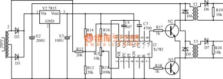
The infrared remote control switch circuit of ceiling lamps
Published:2011/7/3 6:55:00 Author:Borg | Keyword: infrared, remote control, ceiling lamps
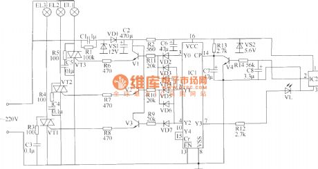
The infrared remote control switch circuit of ceiling lamps which is to be introduced here can be used in the remote controls of domestic electric apparatus(such as TV sets, disc players and videos, etc) to turn on/off the lamps or choose the brightness of the lamps. By pressing a random key on the remote control continuously, the lights of first team are lighting, both the 1st and 2nd teams of light are ON, all the lights of 3 teams are glowing, all the lights of 3 lines are OFF, and the lamps in 1st team are lighting```the lights change in this order.The circuit consists of the power supply circuit, infrared reception circuit, counting/distributor and the control executing circuit.
(View)
View full Circuit Diagram | Comments | Reading(938)
The electric over-voltage relay circuit
Published:2011/7/3 7:31:00 Author:Borg | Keyword: over-voltage relay
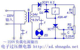
The electric over-voltage relay circuit The circuit is simple, when the power supply voltage is over the limit value, it will take action, the power supply is cut off, which makes sure the load won't be two high. The power supply of the relay and the controllable silicon is turned into 24V by the transformer, and then rectified by D1, the relay and the controllable silicon are connected together in the parallel way. R1 and R2 are the distributing resistors, the control pole LEV can be controlled by adjusting R2, so the SCR can be conducting in the selected voltage. When the power supply voltage reaches the limit value of the SCR, the SCR is conducting.
(View)
View full Circuit Diagram | Comments | Reading(1218)
The anti-parallel or bridge SCR trigger circuit
Published:2011/7/3 7:41:00 Author:Borg | Keyword: anti-parallel, bridge, SCR trigger
View full Circuit Diagram | Comments | Reading(2520)
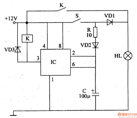
The multi-function time delay switch power supply outlet
Published:2011/7/3 20:16:00 Author:Borg | Keyword: multi-function, time delay switch, power supply

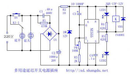
Turning on or off of domestic electric apparatus and lighting lamp is often done after some delayed time, this power supply outlet can meet these needs.Working principle: see as the figure, the circuit consists of the step-down, rectifier, filter and time delay control circuit and other parts.
By pressing AN, the 12V voltage is imposed on the delayer, at the moment, the 2-pin and 6-pin of NE555 are in a high LEV, and 3-pin of NE555 is outputting a low LEV, so relay K gets power, the contactor K1-1 is pulling in upward, and the delay shut outlet is getting power. (View)
View full Circuit Diagram | Comments | Reading(1928)
The single tube time delay pulling in relay circuit
Published:2011/7/3 20:17:00 Author:Borg | Keyword: single tube, time delay, relay circuit
View full Circuit Diagram | Comments | Reading(780)
The single key touch switch circuit
Published:2011/7/3 20:30:00 Author:Borg | Keyword: single key, touch switch
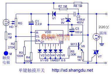
Here is to introduce a single key touch switch circuit composed of CD4017, this circuit is controlled by single touch on the pole, every time it is touched, the switch will take action(ON/OFF) once, whose functions are the same with ordinary switch, and it is convenient to use.The working principle is shown in the figure, of which HD is the neon bulb of tube type, it consists of the self-made photoelectric coupler with resistor RG, and it forms the touching signal input circuit with the touch poles of M and R1. The odd input terminals Q1, Q3,Q5, Q7 and 9Q, etc, of CD4017 are connected with diodes of V2~V6, respectively.
(View)
View full Circuit Diagram | Comments | Reading(2001)
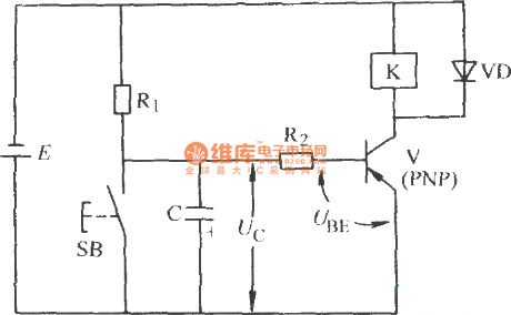
The single tube time delay releasing relay circuit
Published:2011/7/3 20:19:00 Author:Borg | Keyword: single tube, time delay
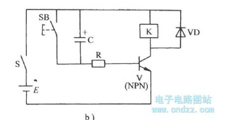
In Figure a) is the PNP tube time delay releasing circuit
In Figure a) is theNPN tube time delay releasing circuit (View)
View full Circuit Diagram | Comments | Reading(1027)
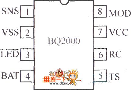
BQ2000 charging controller circuit
Published:2011/7/1 0:58:00 Author:TaoXi | Keyword: charging controller
View full Circuit Diagram | Comments | Reading(667)
example of A/D and D/A converter circuit
Published:2011/6/27 10:00:00 Author:chopper | Keyword: example, A/D and D/A, converter
The picture is the typical instance of digital analog circuit,and it is a A/D and D/A converter circuit.The A/D and D/A integrated chip is on the edge of the digital circuit and analog circuit.Thus,these chips include AGND and DGND,and there is no current going through the ground,the leads need not too thick.
(View)
View full Circuit Diagram | Comments | Reading(621)
landlines of digital and analog circuit on the same placode circuit
Published:2011/6/27 10:13:00 Author:chopper | Keyword: landlines, digital and analog circuit, same placode

When the digital circuit and analog circuit are on the same placode,the trend of the landlines is very important to prevent the noise of digital circuit from mixing into the analog circuit to effect its performance.The digital circuit and analog circuit must be separated physically if they are on the same circuit,because the analog ground AGND and digial ground DGND should be separated definitely.AGND and DGND should be connected at one point,just as picture a,b.
(View)
View full Circuit Diagram | Comments | Reading(600)
power supply and landlines of digital circuit
Published:2011/6/27 21:07:00 Author:chopper | Keyword: power supply, landlines, digital circuit
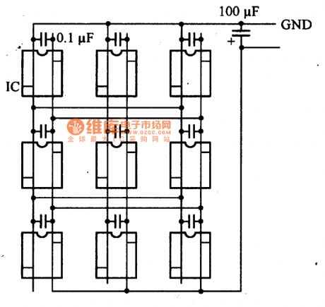
As to digital circuit,the impedance of power supply should be low as possible as we can.The high impedance will effect the circuit.The picture is a connection method of double-sided printed circuit board.On the element installation surface there are horizontal and longitudinal leads,and leads should be short and thick as possible as we can.Additionally,the leads are in grid shape to reduce the circuit impedance when the frequency is high.The waxy capacitance of power supply can reduce the high frequency impedance of leads of power supply.Thus,every IC is connected with a 0.1μF ceramic capacitor.To reduce the low frequency impedance of leads of power supply,we can add a 100μF electrolytic capacitor to the input end of power supply.
(View)
View full Circuit Diagram | Comments | Reading(625)
The underwater pump burglarproof alarm circuit
Published:2011/6/30 23:09:00 Author:qqtang | Keyword: underwater pump, burglarproof alarm
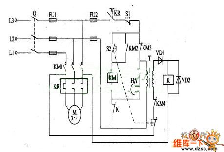
When the irrigating underwater pump is far from the working spot, it is easy to be stolen. The following is to introduce the underwater pump burglarproof alarm, which can deliver alarm signals when the pump is stolen or the pump is malfunctioning, reminding the user of handling in time. The working principle of the circuitThe pump alarm circuit consists of the relay K, diode VD1 and VD2, the power supply transformer T and ring HA, see as the figure.
(View)
View full Circuit Diagram | Comments | Reading(842)
Motorcycle Illuminating Lamp Controller
Published:2011/6/30 6:18:00 Author:Sue | Keyword: Motorcycle, Illuminating Lamp, Controller
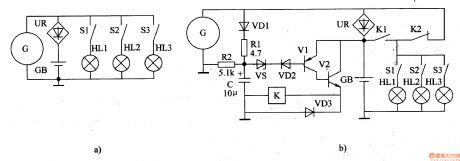
When the speed of the motorcycle is fast, C's voltage will be equal to GB's voltage. VD2,V1 and V2 are disconnected. K is released and AK1 is disconnected. K2 is connected. HL3,HL2,HL1 will be powered by G.
When the speed is slower than a certain value, C's voltage will make VD2 connected. V1,V2 are connected and K is connected. K1 is connected while K2 is disconnected. HL1-HL3 will be powered by GB.
When C is short, R1 will be disconnected to protect the circuit. (View)
View full Circuit Diagram | Comments | Reading(520)
Brake Flash Light
Published:2011/6/30 6:09:00 Author:Sue | Keyword: Brake, Flash, Light
When the oscillator begins to work, 300V high-frequency pulse voltage will be generated on W3. The voltage will be divided into four circuits after rectification. One will be put on the flash light's A terminal directly. One will charge C4. One will charge C3 through R2,R3. One will charge C2 through R2,R4,R5.
When C2-C4 stop charging, V2, VT will be connected. C3 will generate high voltage on T2. The voltage will be put on B,C. Then C2-C4 will be charged quickly. Everytime the brake switch is connected, the flash light will twinkle many times. (View)
View full Circuit Diagram | Comments | Reading(673)
Motor Fluorescent Lamp Circuit
Published:2011/6/30 6:24:00 Author:Sue | Keyword: Motor, Fluorescent Lamp, Circuit
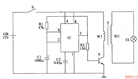
When S is connected, square wave oscillator will begin to work, and IC's pin 3 will output square wave pulse signals. When IC's pin 3 outputs high level, V is connected and T's W1 will have current. When IC's pin 3 outputs low level, V is disconnected and W1's current is cut off, W2 will generate high voltage. EL will be illuminated by the high voltage. (View)
View full Circuit Diagram | Comments | Reading(713)
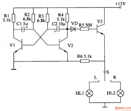
Automobile Steering Flasher (6)
Published:2011/6/30 6:00:00 Author:Sue | Keyword: Automobile, Steering, Flasher
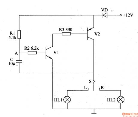
When S is put on L or R , +12V voltage will be put on V2. The other circuit will charge C by VD and R1. When C's voltage reaches a certain value, V1 and V2 will be connected. The left turn lamp HL1 or right turn lamp HL2 will be illuminated. After V2 is connected, C will be discharged by V2,VD. V1,V2 will be connected. HL1, HL2 will be off. Then C will be charged by R1 which will make V1,V2 connected. The circuit keeps on working like this. (View)
View full Circuit Diagram | Comments | Reading(586)
Automobile Steering Flasher (5)
Published:2011/6/30 5:54:00 Author:Sue | Keyword: Automobile, Steering, Flasher
S is the turn lamp switch. HL1 is the left turn lamp switch. HL2 is the right turn lamp switch.
The astable multivibrator will generate low-frequency oscillate signals which will be put on V3. When S is put on L or R , V3 will be connected intermittently, which will make HL1 or HL2 illuminated with a twinkle frequency of70-75 times/min. (View)
View full Circuit Diagram | Comments | Reading(622)
Automobile Steering Flasher (4)
Published:2011/6/30 5:50:00 Author:Sue | Keyword: Automobile, Steering, Flasher
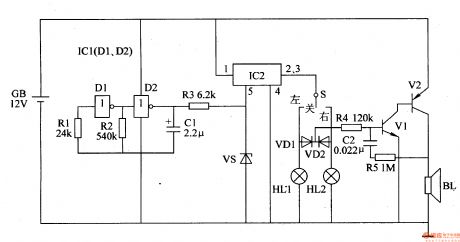
The low-frequency oscillator will generate 1Hz pulse signals which will control HL1 and HL2.
IC2's inner switch will be connected intermittently under the control of the signals. When the pulse signals are positive, IC2's inner switch will be connected. When the signals are negative, IC's inner switch will be disconnected.
When S is put on LEFT , the left turn lamp HL1 will be illuminated and VD1 will be connected intermittently. The indicator will begin to work and BL will make a warning tone. When S is put on RIGHT , the right trun lamp HL2 will be illuminated and VD2 is connected intermittently. The indicator will begin to work. When S is put in middle, HL1 and HL2 are both off and VD1,VD2 are both disconnected. The indicator doesn't work and BL makes no sound. (View)
View full Circuit Diagram | Comments | Reading(505)
| Pages:230/312 At 20221222223224225226227228229230231232233234235236237238239240Under 20 |
Circuit Categories
power supply circuit
Amplifier Circuit
Basic Circuit
LED and Light Circuit
Sensor Circuit
Signal Processing
Electrical Equipment Circuit
Control Circuit
Remote Control Circuit
A/D-D/A Converter Circuit
Audio Circuit
Measuring and Test Circuit
Communication Circuit
Computer-Related Circuit
555 Circuit
Automotive Circuit
Repairing Circuit