
Control Circuit
Index 234
Anti Lost Alarm (3)
Published:2011/6/29 6:28:00 Author:Sue | Keyword: Anti Lost, Alarm
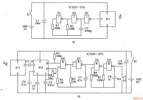
When S1 is connected. IC1 IC2 begin to work. The oscillator consists of D1,D2,R1,R2,C2 will output 10kH signals which will be transformed into 150kHz radio wave and will be sent out.
When IC3 receives the radio wave, its pin 3 will output 10kHz pulse signals. Then its pin 8 will output low level. HA makes no sound.
When the distance is beyond 5m, IC3 will receive no wave and IC4's pin 8 will output high level. The oscillator will begin to work. HA will make an alarm sound. (View)
View full Circuit Diagram | Comments | Reading(1625)
Anti Lost Alarm (2)
Published:2011/6/29 6:21:00 Author:Sue | Keyword: Anti Lost, Alarm
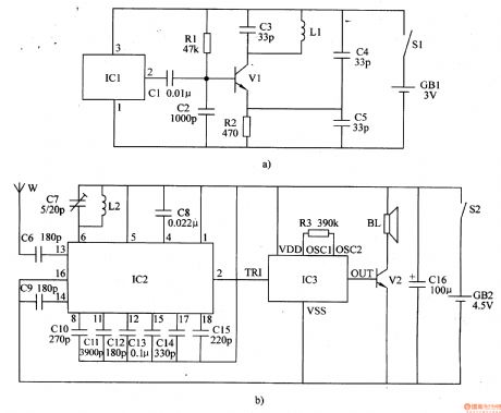
When S1 is connected, IC1 begins to work. Its pin 2 will output oscillate signals which will be emitted by L1.
When W receives the signals, IC2's pin 2 will output low level after the signals are transformed and amplified. IC2's pin 2 will output low level. IC3 doesn't work and BL makes no sound.
When to use the device and when the distance is beyond 5m, W will receive no signals. IC2's pin 2 will output high level. IC3 begins to work. The signals will promote BL to make an alarm sound after the signals are amplified by V2. (View)
View full Circuit Diagram | Comments | Reading(1448)
Anti Lost Alarm (1)
Published:2011/6/29 6:15:00 Author:Sue | Keyword: Anti Lost, Alarm
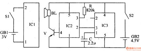
When the distance between the wireless transmitter and the wireless receiver is within 8m, IC2's inner tiny antenna will receive the high-frequency signals emitted by IC1's inner tiny antenna. IC2's pin 2 will output high level after the signals are amplified, detected, delayed and transformed. Its pin 3 will output low level. IC3 doesn't work and BL makes no sound.
When the distance is beyond 8m, the receiver will receive no signals. IC2's pin 2 will output low level and pin 3 will output high level. IC3 will be connected. The signals will promote BL to make an alarm sound after the signals are amplified by V. (View)
View full Circuit Diagram | Comments | Reading(1047)
Plastic Bags Sealing Machine (3)
Published:2011/6/27 2:31:00 Author:Sue | Keyword: Plastic Bags, Sealing, Machine
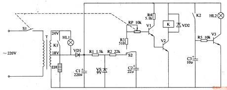
When S1 is on, 220v voltage will generate 18v and 24v voltage after reduction. The 18v voltage will provide the heating control circuit and indicating circuit with working power. The 24v voltage will charge C2. HL1 is illuminated and V1-V3 are disconnected. K is released. EL is not heated and HL2 is not illuminated.
When S2's nomally closed interlock is disconnected, C2 will charge V1's b, and V2 V1 will be connected. K is connected and K2 K1 are connected. EH is heated. HL2 is illuminated. When C2 stops discharging, V1 V2 are disconnected and K is released. EH stops working. The bag is sealed. (View)
View full Circuit Diagram | Comments | Reading(2078)
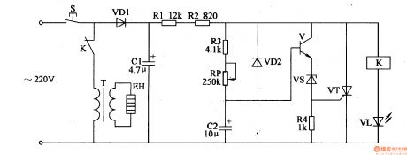
Plastic Bags Sealing Machine (2)
Published:2011/6/27 2:24:00 Author:Sue | Keyword: Plastic Bags, Sealing, Machine
After putting the bag on EH, and push the handle, the 220v voltage will provide V with working power after reduction, rectification and filtration.
When the working power is on, V is disconnected. C1's voltage is put on VT and VT is connected. 220v voltage will be put on T through S and VT. Then it will provide EH with working power after reduction. Then EH will be heated and seal the bag. When C2's voltage reaches 0.7v, V is connected and EH stops working. When the handle is released, S is disconnected and C2 is discharged, prepared to charge for the next time. (View)
View full Circuit Diagram | Comments | Reading(1273)
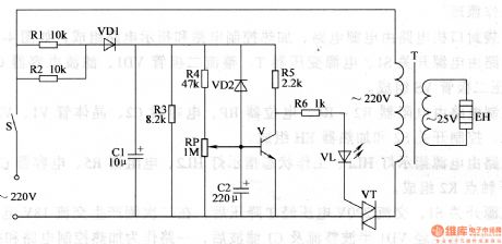
Plastic Bags Sealing Machine (1)
Published:2011/6/27 2:17:00 Author:Sue | Keyword: Plastic Bags, Sealing, Machine
After S is pushed, 220V voltage will provide the circuit with 20v working voltage after rectification, filtration and reduction. V and VT are disconnected and K is connected. VL is illuminated and T begins to work. 220v voltage provides EH with working power and EH will seal the plastic bags. At the same time, C2 charges R3 by RP. When C2's voltage reaches a certain value, V is connected and VT is connected. K is released and VL is off. EH stops working.
When S is released, VT is disconnected and the circuit's working power is cut off. (View)
View full Circuit Diagram | Comments | Reading(2934)
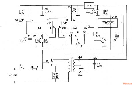
Intermittent Current Controler (7)
Published:2011/6/26 4:56:00 Author:Sue | Keyword: Intermittent, Current, Controler
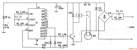
The 220v voltage will provide K and IC with 12v working voltage. VL is illuminated.
When IC begins to work, IC's pin 3 outputs high level and V is connected. K is connected. The working power is on. IC begins to count the working time of T. When timing work is over, IC's Q14 has low level and V is disconnected. K is released. IC's inner counter returns to normal and itgoes into the next period.
It works like this and realises the intermittent current control. (View)
View full Circuit Diagram | Comments | Reading(559)
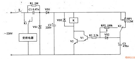
Intermittent Current Controler (6)
Published:2011/6/26 4:46:00 Author:Sue | Keyword: Intermittent, Current, Controler
The 220v voltage can generate 12v voltage to provide the circuit with working power and VL1 will be illuminated.
The moment the power is on, IC's pin 2's and pin 6's voltages are lower than Vcc/3 and pin 3 outputs high level. VL2 is illuminated. K is connected. When voltages of pin 2 and pin 6 are higher than 2Vcc/3, IC's inner circuit will be reversed and K is released. VL2 is off. When voltages of pin2 and pin 6 are lower than Vcc/3, IC's inner circuit is reversed and pin 3 has high level again. K is connected and the working power is off. (View)
View full Circuit Diagram | Comments | Reading(621)
Intermittent Current Controler (5)
Published:2011/6/25 8:10:00 Author:Sue | Keyword: Intermittent, Current, Controler

When S is on, 220V voltage will provide the control circuit will +12V(Vcc) working voltage.
The moment S is on, IC's pin 2 will have low level and pin 3 will have high level. V and K is connected and K1,K2 are disconnected. The working power is on. IC's pin 2 and pin 6 's voltage will keep going up. When the voltagereaches 2Vcc/2, IC's pin 3 will have low level and V is disconnected. The power is cut off. When IC's pin 2 and pin 6 's voltage are going down and reaches Vcc/2, IC's pin 3 will output high level and V is connected. The working power is on again. (View)
View full Circuit Diagram | Comments | Reading(561)
Intermittent Current Controler (4)
Published:2011/6/25 8:02:00 Author:Sue | Keyword: Intermittent, Current, Controler
When S is on, 220V voltage will provide the circuits with 9V working voltage.
The moment S is on, IC's pin 2 has low level, and pin 3 outputs high level. K1 will be connected and A begins to work. VL1 is illuminated.
Then C1 will be charged and the voltage will keep going up. When the voltage exceeds 2Vcc/3, the inner circuit will be reversed and pin 3 will have a low level. A stops working and B begins to work. VL1 is off and VL2 is illuminated.
At the same time, when C1's voltage is lower than Vcc/3, IC's pin 3 will output high level and K1 is connected and K2 is disconnected. A begins to work and B stops working. (View)
View full Circuit Diagram | Comments | Reading(591)
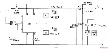
Intermittent Current Controler (3)
Published:2011/6/25 7:56:00 Author:Sue | Keyword: Intermittent, Current, Controler
When S is on, 220V voltage will provide K with 15V working voltage and charge C3 by RP1. When C3's voltage reaches a certain value, VS2 will be connected and K is connected. The controled equipment begins to work. C3 will charge V1 and make V1 V2 connected. The equipment continues working. As C3's voltage keeps going down, and reaches 1.5 V, V1 V2 will be disconnected and K1 K2 will be disconnected. The controled equipment will stop working. C3 will be charged by RP1 again. (View)
View full Circuit Diagram | Comments | Reading(623)
Intermittent Current Controler (2)
Published:2011/6/25 7:52:00 Author:Sue | Keyword: Intermittent, Current, Controler
When the multivibrator begins to work, IC1's pin 3 will outputs square form pulse signals. IC2's pin 3 will output one high level every 10 or 6 minutes and when S3 is set on 1 , the controled equipment will work 1 min every 10 min. When S3 is set on 2 , the equipment will work 1 min every 6 min. V will be connected when IC2's pin 3 is connected and VLC's LED will be illuminated. The controled equipment will begin to work. (View)
View full Circuit Diagram | Comments | Reading(820)
Intermittent Current Controler (1)
Published:2011/6/25 7:46:00 Author:Sue | Keyword: Intermittent, Current, Controler

When the switch is on, the 220V voltage will be divided into 3 circuits. One provides K with 12V working voltage. One provides IC with 5.6V voltage. The other one illuminates VL3.
When IC begins to work, its pin 8outputs low level which will illuminate VL2. Then V1 V3 are disconnected and VL1 is illuminated.
When it stops working, its pin 8outputs high level, which will make V1 V3 connected and VL1 off and VL2 illuminated. (View)
View full Circuit Diagram | Comments | Reading(666)
Timing Controler (1)
Published:2011/6/25 7:33:00 Author:Sue | Keyword: Timing, Controler
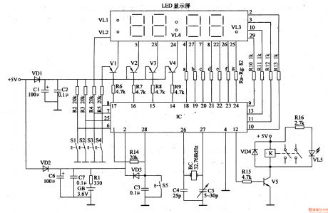
When the swtich is turned on, +5v voltage will provide LED screenwith working power. IC will get electricity and GB will be charged.
When the time can be set, S2 will be used to set the hour and the minute. S3 will be used to add the time figure while S4 can be used to reduce the time figure. When it is in the timer function, S2 can be used to decide the working condition of the timer. When it is in running function, S2 is used to decide the manual state. S3 is used to start the power while S4 is used to cut off the power. (View)
View full Circuit Diagram | Comments | Reading(674)
The multi-function dimmer circuit of special integrated circuits
Published:2011/6/29 0:50:00 Author:Seven | Keyword: multi-function, integrated circuits
In the figure is the multi-function dimmer circuit of HT7760 special integrated circuits, which has four different dimming functions of stepless dimming, step dimming, lights-out delay and circling auto lights-out. B can be a common voltage pottery chip, other parameters are shown in the figure, which have no special regulation.
(View)
View full Circuit Diagram | Comments | Reading(689)
The simple V-MOSFET dimming lamp circuit
Published:2011/6/29 0:43:00 Author:Seven | Keyword: dimming lamp, V-MOSFET
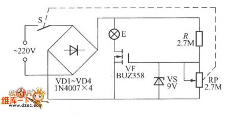
The simple V-MOSFET dimming lamp circuit is shown in the circuit, which harnesses the features of V-MOSFET that its impedance is high and controls the bulb current by adjusting the bias voltage of the V-MOS pipe grid, so that the brightness of the bulb is changed. The power of E is not higher than 60W.
(View)
View full Circuit Diagram | Comments | Reading(1359)
The pulse width speed regultating motor circuit
Published:2011/6/29 5:37:00 Author:Seven | Keyword: pulse width, speed regultating motor
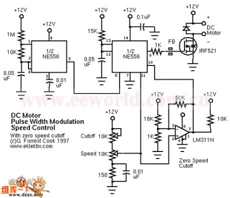
View full Circuit Diagram | Comments | Reading(594)
FSK/ASK 433MHz Emitter Circuit Diagram
Published:2011/6/19 5:15:00 Author:Vicky | Keyword: FSK/ASK 433MHz Emitter
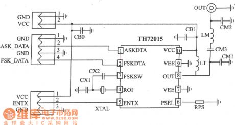
TH72015 applied circuit
TH72015 is a FSK/ASK emitter specially designed for application for European 433 MHz ISM frequency range, which reaches EN 300 220 wireless communication standard. It is available for application in keyless entering system, remote control/remote-measuring system , data communication system and security system etc.
Main technical features are as follows:
·Work frequency: 380~450 MHz;
·Singal-ended RF output;
·FSK modulation rate: DC~40 Kb/s;
·ASK modulation rate up to 40 Kb/s;
·Voltage of power supply: l.9~5.5 V;
·Work current: 3.5~10.7 mA, stand-by current: 0.1μA;
·Output power: -12~+8.5 dBm.
(View)
View full Circuit Diagram | Comments | Reading(1445)
ASK 433MHz Emitter Circuit Diagram
Published:2011/6/19 5:17:00 Author:Vicky | Keyword: ASK 433MHz Emitter
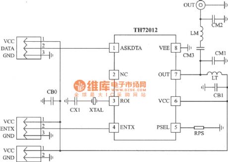
TH72012 applied circuit
TH72012 is monolithic emitter chip which reaches standard of EN 300 220 and the analogs. It is available for keyless entering system, remote control/ remote measuring system, data communication system and security system etc.
Main technical features are as follows;:
·Completely integrated and stable PLL;
·Work frequency: 380~450 MHz;
·Single-ended RF output;
·ASK modulation mode;
·ASK modulation rate up to 40 Kb/s;
·Voltage of power supply: l.9~5.5 V;
·Work current: 3.5~10.7 mA, stand-by current: 0.1μA;
·Output power: -12~+8.5 dBm. (View)
View full Circuit Diagram | Comments | Reading(857)
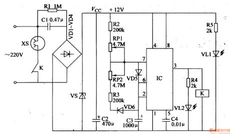
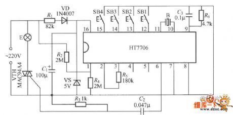
The lighting lamp power-off self-lock switch circuit
Published:2011/6/29 5:59:00 Author:Seven | Keyword: lighting lamp, self-lock switch
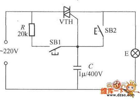
With ordinary wires controlling the lighting lamps, if the power is off, it's hard to tell whether it's ON or OFF, so it always causes the power waste when the power is on at night. If we replace the ordinary wire with the figured circuit, the weakness will be gone, which can self-lock when the power is coming back and the lamp won't be on. VTH is decided by the power of the lighting lamp, which can be the micro plastic packaged dual-way thyristor (3A/600V) of BCR3AM.
(View)
View full Circuit Diagram | Comments | Reading(602)
| Pages:234/312 At 20221222223224225226227228229230231232233234235236237238239240Under 20 |
Circuit Categories
power supply circuit
Amplifier Circuit
Basic Circuit
LED and Light Circuit
Sensor Circuit
Signal Processing
Electrical Equipment Circuit
Control Circuit
Remote Control Circuit
A/D-D/A Converter Circuit
Audio Circuit
Measuring and Test Circuit
Communication Circuit
Computer-Related Circuit
555 Circuit
Automotive Circuit
Repairing Circuit