
Control Circuit
Index 229
electrical equipment overheating "brakes" voice alarming circuit
Published:2011/7/2 2:00:00 Author:John | Keyword: electrical equipment
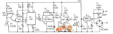
The figure shows the electrical equipment analog voice alarming circuit. It consists of overheating electronic switch, controlled multi-vibrator, analog voice circuits, audio amplifier circuit and AC buck rectifier circuit. The controlled multi-vibrator consists of 555, R2, R3 and Cl and so on. Its multivibrator frequency is that the icon parameter oscillation period To (= 1/fo) is equal to 10s. (View)
View full Circuit Diagram | Comments | Reading(581)
The simple power-off self-lock circuit
Published:2011/7/2 3:14:00 Author:Borg | Keyword: power-off, self-lock
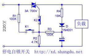
When the grid is supplying power normally, it is like an ordinary switch. By pressing K1, the 220V AC is distributed to the dual-way SCR as the trigger voltage, which makes the SCR conducting. When the SCR is conducting, during the positive half-cycle period of the power supply, a little current is charging C through R4 and D, at the same time, after being distributed by R3 and R2, it charges the SCR; in the passive half-cycle, C discharges R3 and R2 and then triggers the SCR, so that the SCR keeps conducting, which makes sure the load work normally. Once the grid was power-off suddenly, C would be discharging through R3 and R2.
(View)
View full Circuit Diagram | Comments | Reading(956)
The simple electric water tag circuit
Published:2011/7/2 3:01:00 Author:Borg | Keyword: electric water tag

1.working principle The circuit is shown in the figure. PC is a photoelectric coupler, whose feature is that the input and output is fully separated, so it is safe. S is the key switch of step type. The 220V mains is half-wave rectified by the diode D, filtered by capacitor C, and then distributed by R4 and R5, finally, it becomes an output DC voltage of about 10V which is added on the C pole of the triode in the PC. Usually, S is opened, the LED in the PC has no current and is not glowing, the light dependent triode is blocked, the transistor V is blocked. (View)
View full Circuit Diagram | Comments | Reading(643)
The simple and useful 3-key interlock electric switch circuit
Published:2011/7/2 4:16:00 Author:Borg | Keyword: 3-key interlock, electric switch
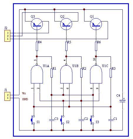
The structure of the circuit is simple, a channel is opened by pressing a corresponding key, meanwhile the other 2 channels are closed. The contactor shake does not affect the working of the circuit, so the anti-disturbance ability is good. If the drive triode in the back was removed, the static power consumption of the circuit would almost 0. If the key was removed, the circuit would be the pulse control.
(View)
View full Circuit Diagram | Comments | Reading(964)
The simple self-lock switch circuit
Published:2011/7/2 2:38:00 Author:Borg | Keyword: self-lock switch
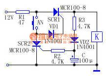
See as the figure, before AN is pressed, SCR1 is blocked, the relay or contactor is still, which is equal to OFF state. When AN is pressed, with the help of R1,AN and VD1,the 12V voltage provide for SCR1 with trigger current which makes it conducting, so K gets power and the contactor is connected with the load and gets into work. As the voltage on the two terminals of the capacitor can't mutate, so SCR2 is not conducting when AN is pressed, the current is charged to C by R3 and VD2. If AN is pressed again, the voltage on C is becoming the trigger voltage of SCR2, which makes SCR2 conducting when AN is blocked. (View)
View full Circuit Diagram | Comments | Reading(864)
An object approaching switch circuit
Published:2011/7/2 2:28:00 Author:Borg | Keyword: switch circuit

View full Circuit Diagram | Comments | Reading(574)
The 3 additional circuits of relays
Published:2011/7/2 4:05:00 Author:Borg | Keyword: additional circuits, relays
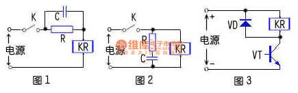
The relay is a common element in electronic circuit, which often consists of the electric switch drive circuit formed by the transistor, relay and others, and other circuits that can change the working features of the relay or fulfill protection function. The additional circuits of the relay has 3 pattens:
1. The relay parallel RC circuit: the circuit type is shown in figure 1, and it is often used in the circuits that the regulated working voltage is lower than the power supply voltage. When the circuit is closed, the current in the relay coil is increaseing. (View)
View full Circuit Diagram | Comments | Reading(607)
The astable circuit of improving the input waveform
Published:2011/7/3 20:52:00 Author:Borg | Keyword: astable circuit, waveform
View full Circuit Diagram | Comments | Reading(670)
The collecting basic coupling single steady circuit
Published:2011/7/2 4:36:00 Author:Borg | Keyword: single steady circuit
View full Circuit Diagram | Comments | Reading(597)
The high-frequency and astable state circuit
Published:2011/7/2 4:19:00 Author:Borg | Keyword: high-frequency, astable state
View full Circuit Diagram | Comments | Reading(671)
The inductance controlled switch circuit (2)
Published:2011/7/2 23:18:00 Author:Borg | Keyword: inductance controlled, switch circuit
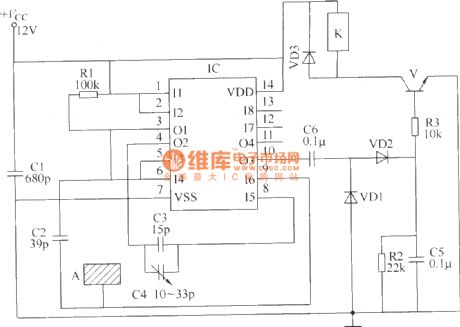
Here is to introduce an inductance controlled switch circuit which is made of the CD4093 digital integrated circuit, it has almost the same functions and features with the separated element inducting control switch. This circuit consists of the inducting electrode plate A, square wave oscillator, trigger control circuit, detecting circuit and control executing circuit, see as the figure.
The inductance controlled switch circuitBy adjusting the volume of capacitor C4, the sensibility of the switch can be changed.Element selection R1~R3 are adopted with the 1/4W carbon film resistor or the metal film resistor. (View)
View full Circuit Diagram | Comments | Reading(960)
The inductance controlled switch circuit (4)
Published:2011/7/2 23:02:00 Author:Borg | Keyword: inductance controlled, switch circuit
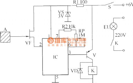
The circuit that will be introduced can be used to control the lighting lamp and auto door, and it can also be used to burglarproof alarm. This circuit consists of the inducting electrode plate A, regulated diode VS, FET transistor VF, music integrated circuit IC, transistor V, relay K, diode VD, resistor R1 and R2, potentiometer RP and power supply switch S, etc, see as the figure.
The inductance controlled switch circuit By adjusting the potentiometer RP, the music time of the IC can be changed, so the lighting time of the lamp can be changed. (View)
View full Circuit Diagram | Comments | Reading(588)
The inductance controlled switch circuit (1)
Published:2011/7/2 22:37:00 Author:Borg | Keyword: inductance control, switch circuit
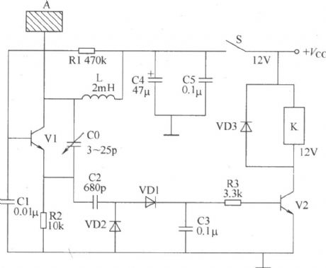
The following is to introduce an inductance controlled switch circuit (capacitance or approach control circuit) made of separated elements, when someone is getting close to the metal current inducting chip, the circuit is on and the load(indicator, alarm or lighting lamp, ventilator and so on) is working. The circuit consists of the inductance pole chip A, RF oscillator, RF detecting circuit and control executing circuit, see as the figure.
By adjusting the volume of C0, the staring/stopping TLV of the RF oscillator can be changed. (View)
View full Circuit Diagram | Comments | Reading(641)
The electric self-lock/interlock switch circuit
Published:2011/7/2 23:33:00 Author:Borg | Keyword: self-lock/interlock, switch circuit

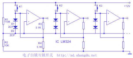
1.switch featuresThe core part of the switch is made of 4 op-amps LM324, with subtle design, each op-amp has two functions: the voltage comparator and the Schmidt trigger. The voltage range is large, and the stages can be adjusted, if it is added with a neutral gear, it can be the general reset, when the circuit cooperates with a digital circuit, they share a power supply, the input/output LEV conforms to the digital circuit connector LEV, as the input impedance of the op-amp is high, the input current of the switch is low. The touch switch, conductive rubber and film switch can be used as the key. (View)
View full Circuit Diagram | Comments | Reading(1338)
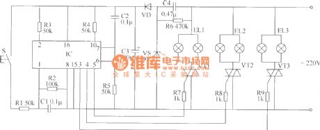
The ceiling lamp control switch circuit (1)
Published:2011/7/2 23:51:00 Author:Borg | Keyword: ceiling lamp, control switch circuit
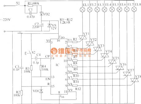
Usually, there are many bulbs in a ceiling lamp, when the power is on, all the bulbs are lighting, if the ceiling lamp is working for a long time, it will be energy-consuming. The ceiling lamp control circuit that will be introduced can choose to control the number of the lighting bulb in 8 bulbs, according to the need. The switch circuit consists of the power supply circuit and control circuit, which is shown in the figure.
Element selection R1 is adopted with the 1/2W metal film resistor; R2~R12 can be the 1/4W carbon film resistor or metal film resistor. (View)
View full Circuit Diagram | Comments | Reading(711)
The ceiling lamp control switch circuit (5)
Published:2011/7/3 0:03:00 Author:Borg | Keyword: ceiling lamp, control switch circuit
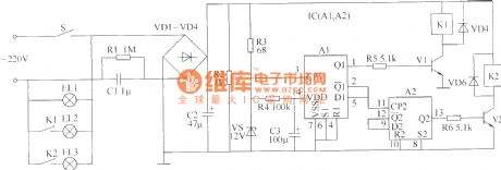
This circuit consists of the power supply circuit, the trigger control circuit A and the trigger control circuit B, see as the figure.
If K1 or K2 can't be locked, then the power should be supplied independently.Element selection R1 is the 1/2W metal film resistor; R2~R6 are made of the 1/4W carbon film resistor or the metal film resistor. C1 is the CBB capacitor whose withstand voltage higher than 400V; C2 and C3 are made of the 25V aluminum electrolytic resistor. VD1~VD6 are all made of the 1N4007 silicon rectifier diode. VS is the 1N4742(1W、12V) silicon rectifier diode. (View)
View full Circuit Diagram | Comments | Reading(659)
SIPMOS control circuit uses the transformer potential isolation
Published:2011/7/1 1:31:00 Author:TaoXi | Keyword: SIPMOS, control circuit, transformer, potential isolation
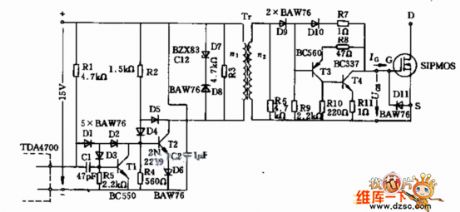
Figure: SIPMOS control circuit uses the transformer potential isolation
(View)
View full Circuit Diagram | Comments | Reading(639)
SIPMOS transistor complementary Darlington control circuit
Published:2011/7/1 1:37:00 Author:TaoXi | Keyword: SIPMOS, transistor, complementary Darlington, control circuit
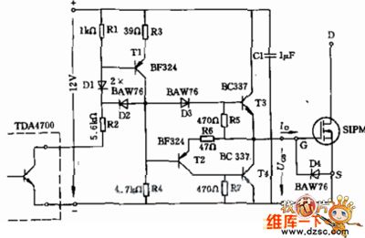
Figure:SIPMOS transistor complementary Darlington control circuit
(View)
View full Circuit Diagram | Comments | Reading(744)
The ceiling lamp control switch circuit (4)
Published:2011/7/3 0:16:00 Author:Borg | Keyword: ceiling lamp, control switch circuit
Here is to introduce a ceiling lamp control switch circuit which consists of the CD4518 digital integrated circuit, it can control each line of bulbs. The circuit consists of the power supply circuit, trigger control circuit and control executing circuit, see as the figure.
Element selectionR1~R5 and R7~R9 are made of the 1/4W carbon film resistor or the metal film resistor; R6 is the 1/2 metal film resistor. C1 and C2 are made of the monolithic capacitor or the dacron capacitor; C3 is the aluminum electrolytic resistor whose withstand voltage is 16V. (View)
View full Circuit Diagram | Comments | Reading(643)
The ceiling lamp control switch circuit (3)
Published:2011/7/3 0:26:00 Author:Borg | Keyword: ceiling lamp, control switch
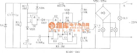
Here is to introduce a ceiling lamp control circuit which is in 2-line control system, the control circuit is installed in the lampshade, and it can control the two states of the lamp through the switch. The circuit consists of the power supply circuit and trigger control circuit, see as the figure.
Element selection Both R1 and R4 are the 1/2W metal film resistor; R2, R3 and R5~R8 are all made of 1/4W metal film resistor; C1 is the aluminum electrolytic resistor whose withstand voltage is 25V; C2 is the aluminum electrolytic resistor whose withstand voltage is over 16V. (View)
View full Circuit Diagram | Comments | Reading(644)
| Pages:229/312 At 20221222223224225226227228229230231232233234235236237238239240Under 20 |
Circuit Categories
power supply circuit
Amplifier Circuit
Basic Circuit
LED and Light Circuit
Sensor Circuit
Signal Processing
Electrical Equipment Circuit
Control Circuit
Remote Control Circuit
A/D-D/A Converter Circuit
Audio Circuit
Measuring and Test Circuit
Communication Circuit
Computer-Related Circuit
555 Circuit
Automotive Circuit
Repairing Circuit