
Control Circuit
Index 231
Automobile Steering Flasher (3)
Published:2011/6/30 5:42:00 Author:Sue | Keyword: Automobile, Steering, Flasher
When S is disconnected, V is disconnected. IC's pin 1 and pin 3 will output high level while the oscillator doesn't work. When S is connected, V is connected. IC's pin 1 will output low level. The oscillator begins to work. IC's pin 3 will output oscillate signals which will make K connected and disconnected intermittently. HLL or HLR will be illuminated simultaneously. When S is put in the middle, V is disconnected. The oscillator will stop working. The turn lamps will be off. (View)
View full Circuit Diagram | Comments | Reading(564)
Automobile Steering Flasher (2)
Published:2011/6/30 5:36:00 Author:Sue | Keyword: Automobile, Steering, Flasher
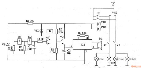
When S2 is connected, +V will provide the square wave oscillator with working power after limitation and stablization. When the oscillator begins to work, it will generate 1Hz square wave oscillate signals which will make V1 connected intermittently and the turn lamp will begin to twinkle. When the square wave signals are positive, V1 is connected and K is connected. HL1, HL2 or HL3, HL4 will be illuminated. When the square wave signals are negative, V1 is disconnected and K is released. The turn lamps will be off.
+V will provide IC2 with 3V working voltage after stablization. After IC2 is connected, music will be generated. (View)
View full Circuit Diagram | Comments | Reading(521)
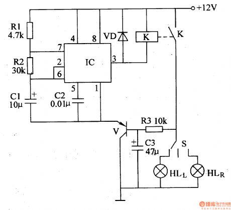
Automobile Steering Flasher (1)
Published:2011/6/30 5:29:00 Author:Sue | Keyword: Automobile, Steering, Flasher
S is the steering switch, and EL1 is left frontturn lamp, EL2 is left rear turn lamp, EL3 is right front turn lamp while EL4 is right rear turn lamp. GB is the storage battery of the automobile.
GB will provide VF with working voltage. The other circuit will provide IC with +12V voltage after limitation, stablization and filtration.
After the multivibrator begins to work, IC's pin 4 will output low-frequency square wave pulse signals. When S is connected, VF will be connected and disconnected intermittently. Then EL1,EL2,EL3,EL4 will start to twinkle. When VF is connected, the turn lamps will be illuminated. When VF is disconnected, the turn lamps will be off. (View)
View full Circuit Diagram | Comments | Reading(625)
Fluorescent Lamp Electronic Ballast (4)
Published:2011/6/26 5:31:00 Author:Sue | Keyword: Fluorescent Lamp, Electronic, Ballast
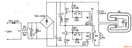
When the power is on, the 220v voltage will provide the oscillator with 300v working voltage after filtration and rectification.
The moment the power is on, one of V1 V2 is connected and V1 V2 will be connected intermittently. The oscillate circuit will be auto-excited. EL will be provided with voltage. When the voltage reaches the discharging voltage of EL, EL will be illuminated. (View)
View full Circuit Diagram | Comments | Reading(3281)
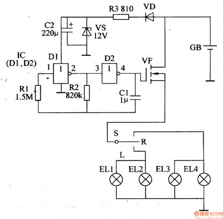
Fluorescent Lamp Electronic Ballast (3)
Published:2011/6/26 5:23:00 Author:Sue | Keyword: Fluorescent Lamp, Electronic, Ballast
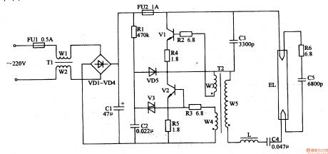
When the power is on, the 220v voltage will provide the oscillate circuit with 300v working voltage after filtration and rectification. It will charge C2 by R1 and when the voltage reaches a certain value, V3 is connected and the oscillate circuit begins to work. V1 and V2 are connected and EL will be provided with working voltage which will illuminate EL. (View)
View full Circuit Diagram | Comments | Reading(4845)
The auto temperature control circuit
Published:2011/6/30 21:27:00 Author:qqtang | Keyword: temperature control
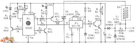
The figured circuit consists of the temperature control sensor switch, the temperature LED display circuit of upper and lower limit, SCR control circuit, analog sound circuit and AC step-down rectifier circuit, etc. The temperature circuit can do the auto control in the within the upper and lower temperature, the detecting precision is ±3℃, so the effect is ideal, and it can also indicate the over-temperature.
(View)
View full Circuit Diagram | Comments | Reading(747)
FM/FSK 433MHz Emitter Circuit Diagram
Published:2011/6/19 7:03:00 Author:Vicky | Keyword: FM/FSK 433MHz Emitter Circuit
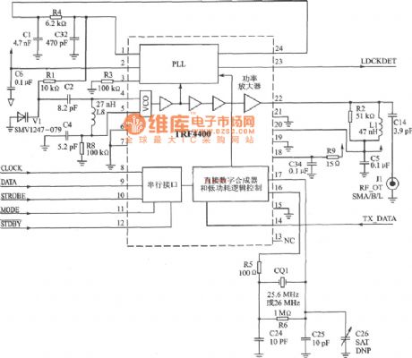
Circuit of TRF4400 application in 433 MHz IS
TRF4400 is an multi-chanell low-cost emitter which can provide full functions. The can meet the requirement of 433MHz frequency band linear (FM) or application of digital(FSK) emitter.
Main technical features are listed as follows:
·Work frequency: 420~450 MHz;
·FM/FSK modulation mode;
·Small demand of exterior fittings;
·Work voltage: 2.2~3.6 V;
·Typical emitting power: 7 dBm;
·Maximum work current of emitter: 75 mA,low-power dissipation mode: 0.5μA;
·Flexible serial interface to be connected to T1 MSP430 microcontroller.
(View)
View full Circuit Diagram | Comments | Reading(1199)
MHz-KH Series Encoding Emitter Module Circuit Diagram
Published:2011/6/26 8:03:00 Author:Vicky | Keyword: MHz-KH Series Encoding Emitter Module
\TXE-433/418/315 MHz—KH series encoding emitter module
TXE-433/418/315 MHz—KH series encoding emitter module , when used together with KH decoding receptor module, can form a highly-reliable wireless link, which send 1 to 8 parallel input states; the address coding is 310 groups; the transmitting distance is over 91.5 m(300 ft). The correspondent receptors are RXD-315-KH(315 MHz)、RXD-418-KH(418 MHz)和RXD-433-KH(433 MHz).
KH series radio frequency encoding emitter is available in remote control system , keyless entering system, garage gate control, lightening control system etc.
Main technical features are listed below:
·No need of other exterior radio frequency component except antenna;
·Maximum output power: +4 dBm;
·Emitting data length: 26 bytes×3
·Work voltage: 2.7~5.2 V;
·Work current: l.5 mA,sleeping mode current: lμA。
(View)
View full Circuit Diagram | Comments | Reading(653)
MHz-LC Series Emitter Module Circuit Diagram
Published:2011/6/19 4:21:00 Author:Vicky | Keyword: MHz-LC Series Emitter Module
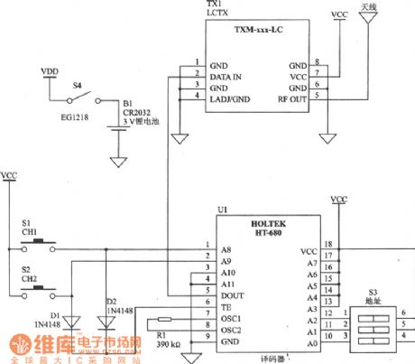
TXM-433/418/315 MHz-LC series module is a low-cost emitter module. It is used with LC series receptor and can transmit analog and digital signal for over 91.5 min (300 ft). LC series requires no tuning device or exterior RF components (except antenna). It is available to be applied in fields such as remote control, remote monitoring, industry process monitoring, periodic data transfer, illuminator control, safe/fire alarm, keyless typing system, medical monitoring/calling system and wireless data transfer etc.
Main technical features are listed as follows:
·Work frequency: 433/418/315 MHz;
·Direct analog or digital input;
·Data transfer rate: greater than 5 Kb/s;
·Voltage of power supply: 2.7~5.2 V;
·Maximum work current: 6MA, sleep mode current: l.5 μA;
·Output power: -4~4 dBm;
·Direct series interface. (View)
View full Circuit Diagram | Comments | Reading(1198)
MHz-RM Series FM/FSK Emitter Module Circuit Diagram
Published:2011/6/19 4:23:00 Author:Vicky | Keyword: MHz-RM Series FM/FSK Emitter Module
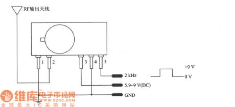
TXM-433/418 MHz-RM series is emitter moduel based on SAW. It is used with RM series receptor and can transmit analog and digital signal for over 152.5m (500 ft). RM series module requires no tuning, regulating or exterior RF component (except antenna). It is available to be applied in fields such as remote monitoring, industry process monitoring, periodic data transfer, illuminator control, safe/fire alarm and remote control etc.
Main technical features are listed as follows:
·Direct analog or digital input;
·Data rate: greater than 10 Kb/s;
·Voltage of power supply: 5.9~9 V;
· Work current: 6 mA.
(View)
View full Circuit Diagram | Comments | Reading(969)
Non-contact sensor alarm circuit
Published:2011/6/24 10:54:00 Author:Fiona | Keyword: Non-contact, sensor alarm

G is representative of sensors in the picture,there is a distributed capacitance Co existing between G and ground, capacitance three-point oscillator composed of Co and L, C1, V1,in the return circuit composed of Co, C1, L,in the view of alternating current path,C0 and C1 are connected in series. When no one is close to G,Co is small,when it connected in series with C1, both ends of the partial pressure of Co is greater than both ends of the partial pressure of C1,the both ends high frequency voltage of Co is fed to V1 base through C3,it's enough to keep three-point oscillator to produce oscillation.
(View)
View full Circuit Diagram | Comments | Reading(1014)
Electronic timer switch circuit
Published:2011/6/27 2:52:00 Author:Fiona | Keyword: Electronic timer, switch
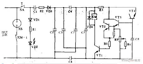
Close the power switch sA,the LED vD2 indicates the work,reduces the voltage by limiting resistor R2 and capacitance c1,rectifys by diode VD3,then filters by balanced symmetrical capacitance c2—c7 and obtains the 6v DC voltage in C7 ends.Because the backward resistance of the emitter junction is large and the input resisters of transistors VTl,VT2,VT3 are connected,The resistance is also very large,so this circuit can increase regular time.When turn on the power,the capacitor c8's voltage is Uc8 = oV, vTl, vT2, VT3 are cut off.vT4 provides the constant charging electric current to C8to make the Uc8 hasten linear growth.
(View)
View full Circuit Diagram | Comments | Reading(1086)
555 continuous recording keeping sound control circuit
Published:2011/6/16 1:47:00 Author:TaoXi | Keyword: 555, continuous recording, keeping, sound control
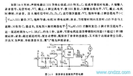
As the figure 14-9 shows, the sound control circuit uses the 555 as the core, the monostable delay circuit is composed of the 555 and R2, C3. The recording signal gets into the circuit from port A, when there is no signal, VT1 cuts off, pin-6 has the high electrical level to reset 555, pin-3 outputs the low electrical level, VT2 cuts off, the motor M stops working, the circuit will not tape. When port A has the signal, the signal is amplified and rectified by D1, D2 and C2, the VT1 conducts, pin-2 has the low electrical level, 555 sets, VT2 conducts, the motor M starts working, the circuit will start taping. When there is no recording signal in a short time, the 555 will not reverse immediately, only when the C3 is charged to the 2/3VDD of pin-6 through R2, the 555 resets, pin-3 has the low electrical level, the delay time td=1.1R2C3, it is about 5 seconds.
(View)
View full Circuit Diagram | Comments | Reading(562)
555 eight stages touch volume controller circuit
Published:2011/6/16 1:32:00 Author:TaoXi | Keyword: 555, eight stages, touch, volume controller
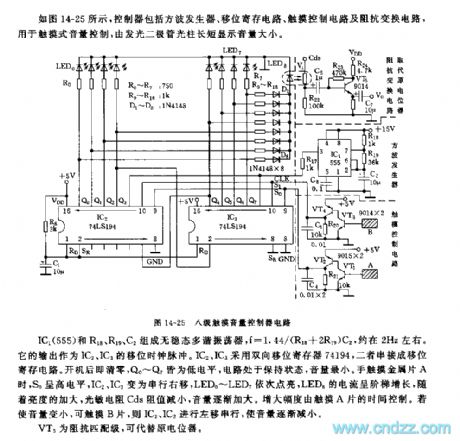
As the figure 14-25 shows, the controller is composed of the square wave generator, the shift register circuit, the touch control circuit and the impedance converting circuit, this controller can be used in the touch volume control, and it displays the volume by the LED light beam.
The astable multivibrator is composed of the IC1 (555) and R18, R19, C2, f=1.44/(R18+2R19)C2, it is about 2Hz. The output of it can be used as the shift clock pulse of the IC2 and IC3. The IC2 and IC3 use the two-way shift register 74194. The Q0-Q7 have the low electrical level, the circuit is in the keep state, the volume is minimum. When the hand touches the sheetmetal A, S0 has the high electrical level, IC2 and IC3 change into the serial right shift, the LED0-LED7 turns on one by one.
(View)
View full Circuit Diagram | Comments | Reading(1225)
The door control,light-dependent control switch circuit
Published:2011/6/27 23:45:00 Author:Fiona | Keyword: The door control, light-dependent control
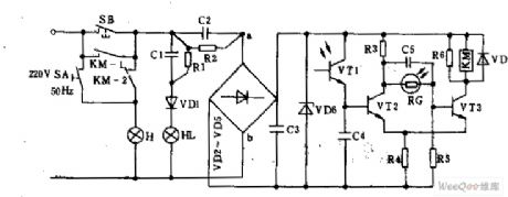
When opens the door,the contact of the key switch SB is closed.The city power reduces voltage by the capacitor C1,rectifys by the diode VDl,indicator light LED is lit.At the same time,the city power reduces voltage by c2,then outputs 12v dc voltage by c3 after filtering. During the day,the resistance of the phototransistor VTl becomes smaller by the light, when it reaches a - threshold, vT2 conducts, the collector of vT2 is low, although thelight dependent resistor RG receives the light but it can not make VT3 conduct.The relay KM is no electricity,the contact KM-1, KM-2 are off,floodlight H is not bright.
(View)
View full Circuit Diagram | Comments | Reading(693)
555 color TV switching power supply circuit
Published:2011/6/15 22:31:00 Author:TaoXi | Keyword: 555, color TV, switching, power supply
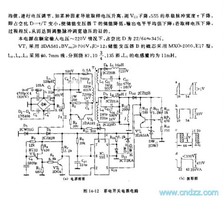
As the figure 14-12 shows, the color TV switching power supply uses the pulse width modulation mode, the pulse width adjustment range is wide, and the voltage stabilizing effect is good, when the input voltage is in the range of 12 to 280V, the output DC voltage is +110V+/-1V.
The double-base port transistor relaxation oscillator is composed of the VT2 and R3, R5, C9, it is used as the time base pulse source, and it is amplified by the VT3 that can be used as the trigger pulse of IC1(555). The controllable monostable trigger circuit is composed of the 555 and the R8, C10. The temporary stability time depends not only on the R8 and the charging time constant of C10, but also the sampling voltage VCT. By changing the duty ratio of the 555's output pulse, you can change the voltage. The output square wave of 555 adds to the power amplifier tube VT1 to encourage the switching power supply of the collector load.
(View)
View full Circuit Diagram | Comments | Reading(1415)
555 touch mode 10 stages volume automatic regulator circuit
Published:2011/6/16 2:01:00 Author:TaoXi | Keyword: 555, touch mode, 10 stages, volume, automatic regulator
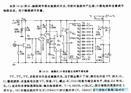
As the figure 14-24 shows, the touch regulator is composed of the touch switch, the controllable time base pulse generator, the counting circuit and the volume control circuit, this touch regulator can be used to touching control the volume.
The touch switch is composed of the VT1, VT2, VT3 and the resistance capacitance components. When the hand touches the sheetmetal T, the induced voltage is amplified by VT1, then it is rectified and filted by D1 and C1, the DC voltage conducts the VT2, and the VT3 cuts off, the reset port of IC1(555) has the high electrical level, the multivibrator which is composed of the 555 and R7,R8,C2 starts working to output the oscillation pulse. T=0.693(R7+2R8)C2, the cycle of the figure parameter is about 3 seconds. The output pulse of 555 can be used as the count clock CP of the IC2(CD4017). The CD4017 is the decimal counter / pulse distributor.
(View)
View full Circuit Diagram | Comments | Reading(1268)
555 fridge electricity saving protector circuit
Published:2011/6/16 3:17:00 Author:TaoXi | Keyword: 555, fridge, electricity saving, protector
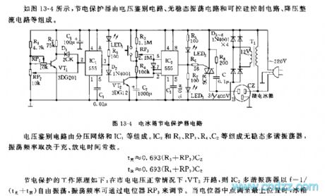
As the figure 13-4 shows, the electricity saving protector is composed of the voltage identification circuit, the astable oscillator circuit and the SCR control circuit, the step-down rectifier circuit.
The voltage identification circuit is composed of the potential-divider network and the IC1.etc. The astable multivibrator is composed of the IC2 and R3, RP3, R4, C2, the oscillation frequency depends on the charge and discharge time constant.
The working principle of the electricity saving is: when the voltage of city electricity is normal, the VT2 is in the open circuit state, so the oscillation frequency of the multivibrator IC2 can be adjusted by the potentiometer RP3. When the voltage of city electricity is lower than the refrigerator normal work voltage 175V, the circuit IC1 turns, pin-3 outputs the high electrical level to conduct the VT2.
(View)
View full Circuit Diagram | Comments | Reading(594)
555 large roller-type washing machine electric controller circuit
Published:2011/6/16 3:36:00 Author:TaoXi | Keyword: 555, large roller-type, washing machine, electric controller
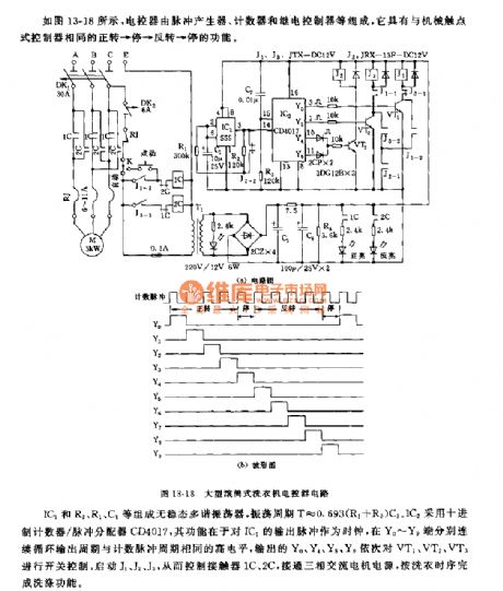
As the figure 13-18 shows, the electric controller is composed of the pulse generator, the counter and the relay controller.etc, it has the same functions with the mechanical contact point type controller.
The astable multivibrator is composed of the IC1 and R2, R1, C1, the oscillation period T=0.693(R1+R2)C1. IC2 uses the decimal counter / pulse distributor CD4017, it can be used as the output pulse clock of the IC1, and the ports Y0-Y9 continuously outputs the high level which has the same cycle with the count pulse respectively, the Y0, Y4, Y5 and Y9 successively control the VT1,VT2 and VT3, they start the J1,J2 and J3 to control the contactors 1C and 2C.
(View)
View full Circuit Diagram | Comments | Reading(1120)
Optical remote control power switch circuit
Published:2011/6/28 0:12:00 Author:Fiona | Keyword: Optical remote control, power switch
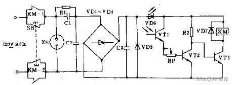
It is a light-controlled power remote control equipment,it can be used for the light of the torch triggering.The circuit consists of two parts:one is the light control circuit;the other one is controlled circuit.The light-controlled part consists of the photoelectric transistor VT1,transistor potentiometer RP and phase transistor VT2.The controlled part consists of the transistor VT3 and the relay KM.When the key switch SB is pressed,the both ends of the voltage-regulator diode vD5 obtains the l 2V DC voltage.The light-emitting diode VD6 displays work.Resistor Rl provides bleeder current loop to the capacitor C1.vD7 is the protection diode.
(View)
View full Circuit Diagram | Comments | Reading(1153)
| Pages:231/312 At 20221222223224225226227228229230231232233234235236237238239240Under 20 |
Circuit Categories
power supply circuit
Amplifier Circuit
Basic Circuit
LED and Light Circuit
Sensor Circuit
Signal Processing
Electrical Equipment Circuit
Control Circuit
Remote Control Circuit
A/D-D/A Converter Circuit
Audio Circuit
Measuring and Test Circuit
Communication Circuit
Computer-Related Circuit
555 Circuit
Automotive Circuit
Repairing Circuit