
Control Circuit
Index 239
555 long delay timer circuit 2
Published:2011/6/20 7:49:00 Author:TaoXi | Keyword: 555, long delay, timer

The difference between this monostable delay circuit which is composed of the 555 and the normal monostable delay circuit is the pin-5 of this circuit is connected with the power supply voltage port through the diode D1. So the 555's control port pin-5's (it is connected with the circuit's internal voltage division point 2UDD/3) threshold voltage is improved to 12V-0.7V=11.3V, this makes the charging time of the capacitance C to be extended greatly. The timing time of the figure parameters is 73 minutes. If you press the button, the 555 sets, the relay closes. After 73 minutes, the relay releases.
(View)
View full Circuit Diagram | Comments | Reading(936)
CMOS system power supply interface-AC switch circuit
Published:2011/6/20 19:06:00 Author:TaoXi | Keyword: CMOS, system, power supply, interface, AC, switch
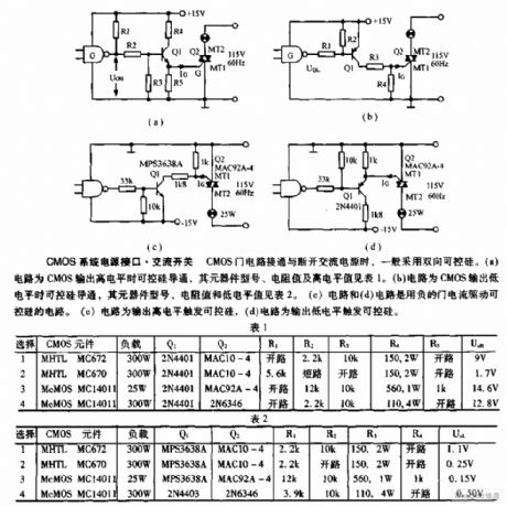
When the CMOS gate circuit turns on and turns off, the circuit usually use the two-way SCR. Circuit (a) is the SCR conduction when the CMOS outputs the high level, the component model, resistance value and the high level value is as shown in table 1. Circuit (b) is the SCR conduction when the CMOS outputs the low level, the component model, resistance value and the high level value is as shown in table 2. Circuit (c) and circuit (d) are the SCR circuits which are drived by the negative gate current. Circuit (c) is the SCR which is triggered by the output high level, circuit (d) is the SCR which is triggered by the output low level.
(View)
View full Circuit Diagram | Comments | Reading(693)
TAl218N video,audio converting switch integrated circuit
Published:2011/6/16 22:45:00 Author:chopper | Keyword: video,audio, converting, switch integrated circuit
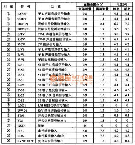
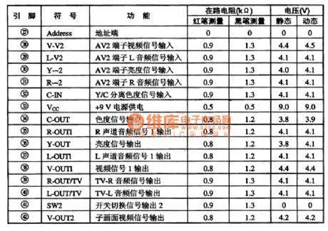
TAl218N is a video/audio converting switch circuit,and it is applied to homemade and import large-screen colour TVs widely.1.function characteristicsTAl218N integrated circuit includes I2C bus interface circuit,main/sprite video signal switching circuit,TV/AV audio switching circuit,Y/C separation signal switching circuit,TV video/audio switching circuit,sub-audio,flare,luminance signal switching circuit,L/H,U/V frequency band switching circuit,and other miscellaneous function circuits.
(View)
View full Circuit Diagram | Comments | Reading(674)
STVO117A digital video coding integrated circuit
Published:2011/6/14 9:16:00 Author:chopper | Keyword: digital video, coding, integrated circuit
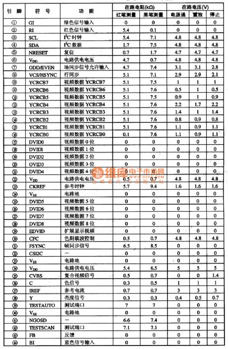
STVO117A is a digital video coding integrated circuit produced by French Company SGS-THOMSON and it is applied to various homemade and import DVD players.1.function characteristicsSTVO117A integrated circuit adopts I2C bus-mastering,and it can code input 8bit or 16bit video data stream into analog composite video signal or S video Y/C signal.It includes multipath output selector,matrixing circuit,modulator,caption generator,color sub-carrier combiner circuit and clock sync generator,three 9bit DAC circuit and IC2 bus interface circuit.2.function and data of pinsSTV0117A integrated circuit adopts single inline package.The function and data of pins of integrated circuit are shown as chart 1.
(View)
View full Circuit Diagram | Comments | Reading(649)
Three-phase power supply phase-lack protection circuit
Published:2011/6/24 21:34:00 Author:TaoXi | Keyword: Three-phase, power supply, phase-lack, protection circuit
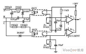
The three-phase power supply phase-lack protection circuit is as shown in the figure. If any phase of the A, B, C is lacking, the optical coupler output level is lower than the reference voltage of the comparator's reverse phase input port, the comparator outputs the low level to blockade the PWM drive signal and turn off the power. If you change the comparator's input polarity, it can be used as the high level PWM blockading signal. This kind of phase-lack protection circuit uses the opto-isolated strong electric, it is safe and reliable, the RP1 and RP2 can be used to adjust the phase-lack protection movement threshold.
(View)
View full Circuit Diagram | Comments | Reading(851)
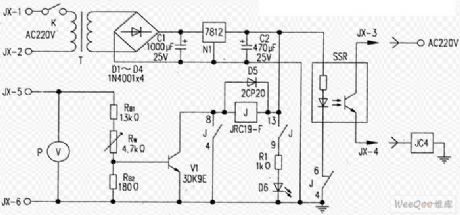
Over-voltage protection circuit with the automatic reset function
Published:2011/6/24 21:51:00 Author:TaoXi | Keyword: Over-voltage, protection circuit, automatic, reset function
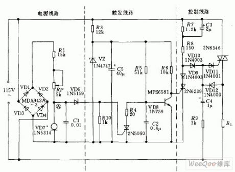
This circuit is composed of the power supply circuit, the trigger starting circuit and the control circuit, it controls the load RL to turn on and off the power through the two-way thyristor ZN*6. Once the voltage of the AC power supply is too high, the A point voltage of the current stabilization component 1N5314 will increase to conduct the unidirectional thyristor 2N5060 and cut off the transistor 2N6239, so the main two-way thyristor cuts off to make the load away from the overvoltage damage.
(View)
View full Circuit Diagram | Comments | Reading(678)
demodulator circuit
Published:2011/6/14 9:30:00 Author:chopper | Keyword: demodulator
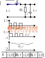
I.The operating principle of demodulatorDemodulator is a important part of modulation DC amplifier circuit.It can restore the AC voltage which has been amplified to the DC voltage,and its size and polarity are according to the width and phase position of the AC voltage.The following picture is the principle of the demodulator.RL is a load,C is a filter capacitor to smooth the output DC voltage.Demodulation switch K is of the same frequency with input AC singal,Vi.
(View)
View full Circuit Diagram | Comments | Reading(621)
555 long delay timer circuit 1
Published:2011/6/20 8:02:00 Author:TaoXi | Keyword: 555, long delay, timer circuit
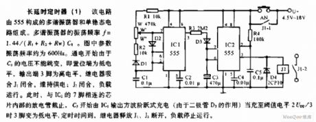
This circuit is composed of the multivibrator (which is composed of the 555) and the monostable circuit. The oscillation frequency of the multivibrator f=1.44/(R1+R2+Rw)C1. The oscillation frequency of the figure parameters is about 600Hz. When the power turns on, the voltage of C5 can not change, so the set port has the low electrical level, the output port pin-3 has the high electrical level, the relay closes, the J1 closes to maintain the power supply; the J2 closes, the load operates. At this time, the internal disrharge tube which is connected with the pin-7 of the IC2 cuts off, the C3 is charged by the output of IC1 with the square-wave step type. When the threshold level is 2UDD/3, pin-3 has the low level, the timing time is up, the relay releases, the J1 and J2 cuts off, the load stops working.
(View)
View full Circuit Diagram | Comments | Reading(1195)
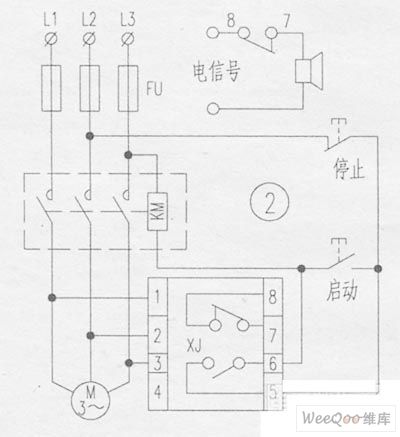
Infrared ray induction switch circuit
Published:2011/6/24 0:47:00 Author:TaoXi | Keyword: Infrared ray, induction switch
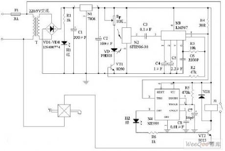
The infrared ray induction switch circuit that can be used in the infrared automatic hand washing device and the sit implement is as shown in the figure.
(View)
View full Circuit Diagram | Comments | Reading(837)
Simple flashing light circuit with the thyristor
Published:2011/6/24 0:52:00 Author:TaoXi | Keyword: Simple, flashing light, thyristor
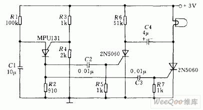
The MPU131 is designed as one kind of program-controlled thyristor that can be used in the relaxation oscillator circuit which is composed of the R1 and C1, the output of it respectively controls two unidirectional thyristors 2N5060 to make the low voltage (2V) indicator light to send out the timing flash.
(View)
View full Circuit Diagram | Comments | Reading(1093)
FM transmitter over-voltage protection circuit
Published:2011/6/24 1:08:00 Author:TaoXi | Keyword: FM transmitter, over-voltage, protection circuit
The actuator of the FM302E—I FM transmitter uses the HPB-1210 motherboard which is produced by the NEC company. This device modulates the frequency of carrier wave directly, and it uses the phase-locked frequency stability technology and the frequency synthesis technology. The former stage power amplifier (BLF-177 mosfet) is directly promoted by the actuator, the maximum output power is 150W. The power adds to the final stage through the circulator that can be used as the driver stage of the last stage vacuum tube's power amplifier. The pre-amplifier power supply uses the 4NICK48 integrated power supply. Unfortunately, this stage has no over-voltage protection circuit and the DC voltage indication function, this makes this stage occurs some faults such as: the actuator output is normal, but this stage and the last stage have no output power.
(View)
View full Circuit Diagram | Comments | Reading(673)
Motor phase broken phase protector circuit
Published:2011/6/24 1:28:00 Author:TaoXi | Keyword: Motor phase, broken phase, protector circuit
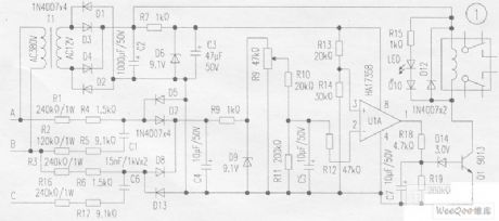
Working principle:
The A, B, C are connected with the A, B, C phases of the AC380V power line network, the phase-shift circuit is composed of the R1, R4, R2, R5, C1, R3, R6, R16, R17, C6. When the voltage is normal (the phase sequence is correct and no phase-lack), the vector voltage of the rectifier input port which is composed of the diodes D5, D7, D8, D13 is small, the rectified voltage is small too. When the phase sequence is wrong or the phase is incomplete, the output voltage instantaneous up to 13V. The voltage is filted by V4, limited by R8 and then is stabilized by D9, at last it is send to the pin-2 of the comparator LM358 through the current limiting resistor R12, it is used as the detected signal voltage.
(View)
View full Circuit Diagram | Comments | Reading(1180)
Simple voltage maintainer circuit
Published:2011/6/21 7:14:00 Author:TaoXi | Keyword: Simple, voltage maintainer
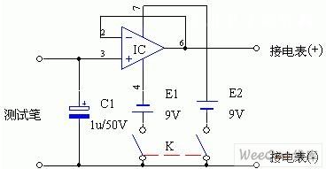
In the figure, the IC uses the general type integrated operational amplifier such as the UA741, and the operational amplifier is connected into the 1:1 voltage follower, the input impedance is very high, but the gain is 1, actually it plays the impedance transformation function. If you connected a capacitance C1 at the in-phase input port of IC, the C1 is called the test holding capacitor. When the test meter or test pen is connected with the test point, the voltage of test point charges the test holding capacitor C1, after about 1 second, the C1 is charged to the measured voltage. When the test meter or test pen is removed from the test point, C1 discharges through the input impedance of integrated operational amplifier.
(View)
View full Circuit Diagram | Comments | Reading(711)
Low-frequency amplification feedback circuit
Published:2011/6/20 5:48:00 Author:John
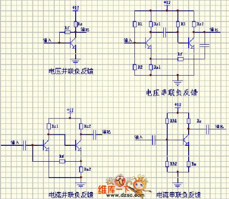
Low-frequency amplification feedback circuit is shown.
(View)
View full Circuit Diagram | Comments | Reading(607)
Analog quantity input signal regulating circuit
Published:2011/6/21 8:31:00 Author:TaoXi | Keyword: Analog quantity, input signal, regulating circuit
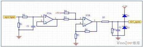
The data acquisition circuit is mainly responsible for the conversion of the analog signals such as the voltage and current. Because the detected voltage and current quantity value is large, the value is far more than the allowed input signal range of DSP, so we need to reduce the value of these analog signals, and change the current quantity into the voltage quantity, also we need to change the dual-polarity signal into the single-polarity signal, and match the level, the A/D is sent into the DSP for operating. The realization method is summarized as follow: the voltage and current signals are converted by the current model Hall sensor, and form the voltage signal which is proportional to the original signal on the high precision sampling resistance.
(View)
View full Circuit Diagram | Comments | Reading(538)
High efficiency white LED driving circuit uses the single-cell lithium battery as the power
Published:2011/6/21 8:47:00 Author:TaoXi | Keyword: High efficiency, white LED, driving circuit, single-cell, lithium battery
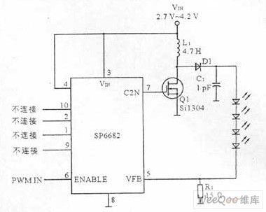
The white LED driving circuit is composed of the white LED driver and the external circuits (includes the transistor, the diode, the inductor, the capacitor and the resistor). The white LED driving circuit needs a constant current source, the current is 15mA~20mA. The luminance of the LED depends on the positive current, so we use some white LEDs in series to ensure every white LED has the same current. The four series white LEDs need 14V voltage, by using the step-up voltage stabilizer to promote the operating voltage of the single-cell lithium battery (2.7V~4.2V), we can get this 14V voltage. The high efficiency white LED driving circuit that uses the single-cell lithium battery (2.7V~4.2V) as the power is as shown in the figure.
(View)
View full Circuit Diagram | Comments | Reading(999)
Light isolation solid power relay circuit
Published:2011/6/22 2:52:00 Author:TaoXi | Keyword: Light isolation, solid, power relay
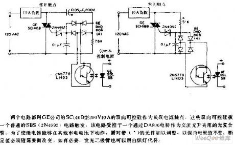
The two circuits use the SC146B type 200V, 10A bidirectional thyristor as the load current contact point which is produced by the GE company. The bidirectional thyristors are triggered by a normal SBS(2N4992) circuit. This circuit is controlled by a light composite tube which can be used as the AC light switch through the DA806 bridge. In order to make this relay to work in other city electricity voltage, we need to adjust the components with the * mark to maintain the current. The rated value needs to be changed according to the need. If necessary, we can use the incandescent lamp to replace the light-emitting diode.
(View)
View full Circuit Diagram | Comments | Reading(721)
Adjustable light detection switch circuit
Published:2011/6/22 3:38:00 Author:TaoXi | Keyword: Adjustable light, detection, switch circuit
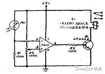
The R2 can be used to set the threshold value of the circuit. When the light intensity of the PC1 surface reduces, the resistance (a tin sulfide light resistance) of PC1 increases. This makes the voltage of 741 reverse phase input port to reduce. When you use the R2 to adjust the reference voltage of 741 in-phase port, as long as the PC1 has no light, the comparator will has the low level, this conducts Q1 and makes the relay K1 to act.
(View)
View full Circuit Diagram | Comments | Reading(757)
Motor control circuit with the transistor and the single thyristor
Published:2011/6/23 2:30:00 Author:TaoXi | Keyword: Motor, control circuit, transistor, single thyristor
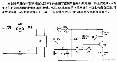
This circuit uses the transistor phase shifting trigger and the unidirectional thyristor to control the full wave voltage of the series excitation motor circuit, so we can control the motor speed in the wide range. The resistor R5 is connected in the unidirectional thyristor main circuit in series to form the negative feedback, this method can steady the speed. The numerical value of R5 is 0.1~1Ω. The function of the diode rectifier bridge Br is to change the AC into DC.
(View)
View full Circuit Diagram | Comments | Reading(628)
Serving guest doorbell and dog alarming circuit diagram
Published:2011/6/23 22:11:00 Author:Nicole | Keyword: Serving guest doorbell, dog alarming
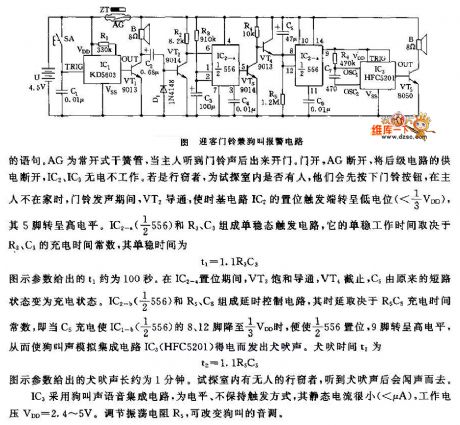
The monostable trigger circuit is composed of IC2-m(1/2 556)and R3, C3, its monostable working time is decided by R3, C3's charge time constant, the monostable time is t1=1.1R3C3. The graphic parameter t1 is about 100s. In the period of IC2-a is set, VT3 is saturation conduction, VT4 cut off, C5 changes from the short circuit state to charge state. The delay control circuit is made of IC2-b(1/2 566)and R5, C5, the delay depends on the R5C5's charge time constant, namely, when IC1-b(1/2 566)'s 8 foot and 12 foot are dropped to 1/3VDD by C5's charge, 1/2 566 is set, 9 foot turns to high level, then the dog braying analog integrated circuit(HFC5201)obtains electricity and it sends out barking. The barking time t2 is t2=1.1R5C5. The graphic parameter t2 is about 1 minute.
(View)
View full Circuit Diagram | Comments | Reading(693)
| Pages:239/312 At 20221222223224225226227228229230231232233234235236237238239240Under 20 |
Circuit Categories
power supply circuit
Amplifier Circuit
Basic Circuit
LED and Light Circuit
Sensor Circuit
Signal Processing
Electrical Equipment Circuit
Control Circuit
Remote Control Circuit
A/D-D/A Converter Circuit
Audio Circuit
Measuring and Test Circuit
Communication Circuit
Computer-Related Circuit
555 Circuit
Automotive Circuit
Repairing Circuit