
Control Circuit
Index 224
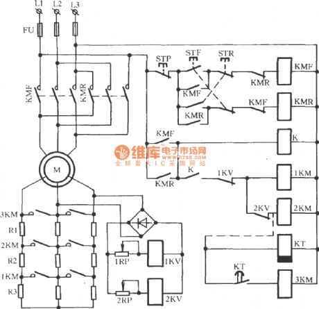
Frequency sensitive resistor starting and wound rotor type induction motor automatic reversing circuit
Published:2011/7/5 9:59:00 Author:John | Keyword: induction motor, wound rotor, Frequency sensitive resistor
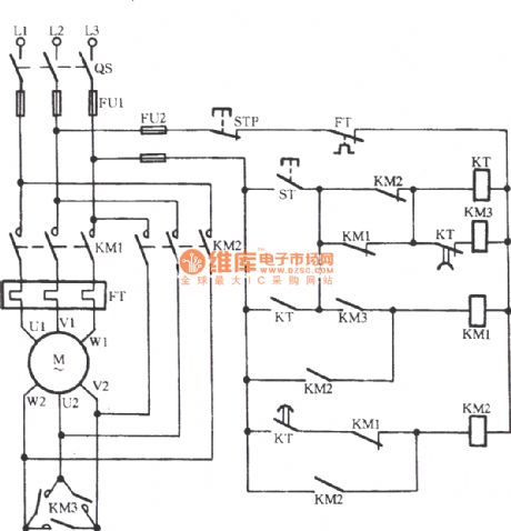
As for the shown figure, the forward starting button STF is pressed to lead the coil KMF to be energized. And the motor is connected to frequency sensitive resistor in series for starting. At the same time, the relay KT starts to timing. When the setting time lKT is reached, its normally opening momentary contact closes. Then the contactor KM suctions to be self-protected. Meanwhile, the KT coil circuit is cut. KM’s main contacts will short the L and the motor runs into full-voltage operation. Press the STP and the motor stops. The operating principle of inversing operation is the same.
(View)
View full Circuit Diagram | Comments | Reading(2047)
Frequency sensitive resistor starting style wound rotor induction motor manual direction switching circuit
Published:2011/7/5 9:51:00 Author:John | Keyword: Frequency sensitive resistor, wound rotor, induction motor
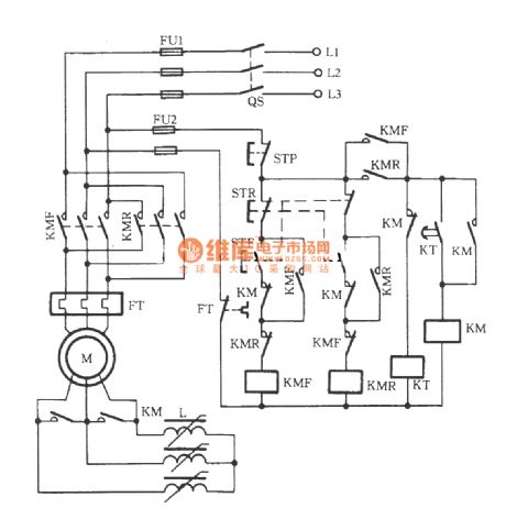
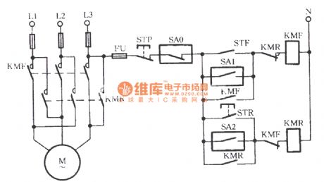
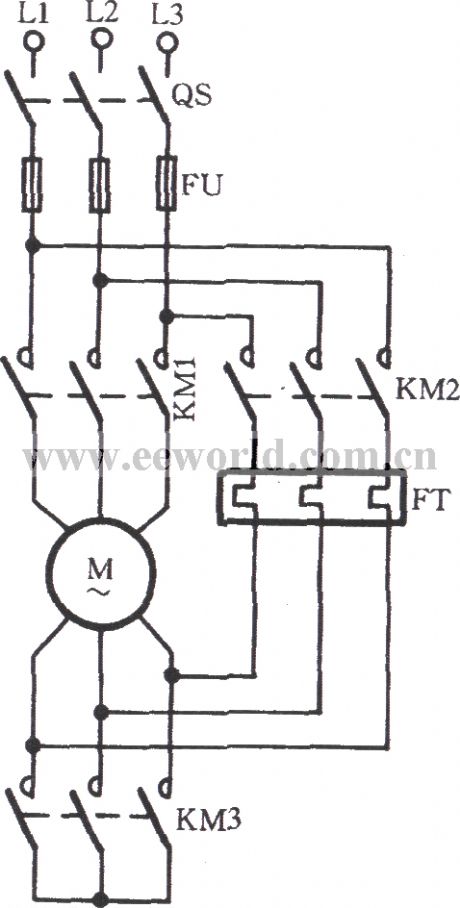
The figure shows a manual-start reversible circuit. The forward starting button STF is pressed and another pair of normally closed contacts of STF disconnect. So the reverse coil KMR loop is cut. At this time, the forward KMF coil pulls and the wound rotor motor is connected with frequency sensitive resistor L in series. It is at the starting state and its speed gradually increases. When the speed rises to about 70% of rated speed, press the running button SN is pressed to lead the KM3 to coil and be self-protected. And the frequency sensitive resistor is shorted. The motor runs into full-voltage operation. When the process is completed, press the STP to park. Similarly, press the button STR and the motor will start to start on the reverse. Press the SN for running into the full-voltage operation state.
(View)
View full Circuit Diagram | Comments | Reading(706)
Zero-volt adjustment start circuit of the W317 voltage stabilizer
Published:2011/7/5 19:37:00 Author:Christina | Keyword: Zero-volt, adjustment, start circuit, voltage stabilizer
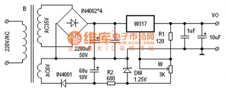
If we use the W317 to make the voltage stabilizer, because the limit of the constitution of the internal circuit, the minimum output voltage is 1.25V. The circuit in the figure can make the voltage to be adjusted from 0V.
The difference of this circuit and the W317 basic application circuit is a group of negative voltage auxiliary power supply. The regulator tube DW positive electrode's voltage to earth is -1.25V, the bottom of the voltage regulating potentiometer W is not connected with the ground but is connected with the positive electrode of the voltage regulating tube, the output voltage of the voltage stabilization power supply is also from the position between the output port and the ground of the three terminal regulator.
(View)
View full Circuit Diagram | Comments | Reading(640)
starting button on installing light circuit
Published:2011/7/5 8:46:00 Author:John | Keyword: starting button, light
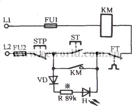
Typically, the motor’s starting button ST and stopping button STP both have no lights. Therefore, it is inconvenient to observe whether the motor work on the operation table or screen. A light (LED H) is installed on the starting button, just as shown in the figure. H is usually lit. But when the ST is pressed, KM is pull and its normally open auxiliary contact KM closes. Then the H is short only to find that the light is not lit. The on-and-off of the light can indicate whether the motor is turned on.
(View)
View full Circuit Diagram | Comments | Reading(763)
Ordinary fan circuit
Published:2011/7/5 10:36:00 Author:John | Keyword: Ordinary fan

The figure shows the 400mm ordinary fan circuit. In the figure, M and LA, LR are respectively the single-phase motor rotor, the auxiliary winding and main winding. C is the starting capacitor and L is the governor. H is the indicator. The 1,2,3 all indicate the wind speed gear switch, which is respectively marked as high, medium and low speed gear.
(View)
View full Circuit Diagram | Comments | Reading(1652)
anti-arcing Y-△ starting circuit within load
Published:2011/7/5 10:38:00 Author:John
View full Circuit Diagram | Comments | Reading(723)
motor running with emitting sound and light signals circuit
Published:2011/7/5 10:56:00 Author:John | Keyword: motor, sound, light
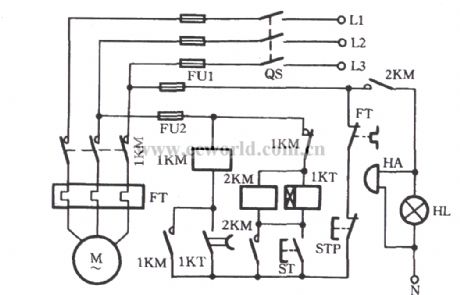
As for some heavy equipment, there is a wide moving range for dragging mechanical components by motor. If there is no audible signal prior to the actual starting, it is likely to cause casualties. Circuit shown is designed to solve this problem. During the starting process, the ST is pressed to coil the contactor 2KM. Then, the bell HA and signal light HL are both driven to give driving signals, aiming to urge people to get out immediately. At the same time, electrical time relay 1KT is energized to work and the timing process starts. After about 1 minute (with adjustable time), 1KT’s normally opening contact closes to induct 1KM. And 1KM is self-locked to start the motor M.
(View)
View full Circuit Diagram | Comments | Reading(855)
automatically switching circuit for preventing Y-△ starter from starting
Published:2011/7/5 10:45:00 Author:John | Keyword: Y-△ starter
View full Circuit Diagram | Comments | Reading(991)
Y-△ starting circuit for preventing arcing short
Published:2011/7/5 10:57:00 Author:John | Keyword: Y-△ starting circuit
View full Circuit Diagram | Comments | Reading(703)
thermal electric resistor block protection circuit
Published:2011/7/5 4:07:00 Author:John | Keyword: thermal electric resistor

View full Circuit Diagram | Comments | Reading(855)
grinding mill automatic grinding gate circuit
Published:2011/7/5 4:08:00 Author:John | Keyword: grinding mill

View full Circuit Diagram | Comments | Reading(857)
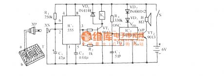
Automatic temperature control of the poultry house and alarming circuit
Published:2011/7/5 4:26:00 Author:John | Keyword: poultry house, automatic temperature control
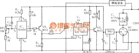
PDF for related components can be downloaded.SL6169012KD-5601378159013The circuit is as shown, which consists of the low temperature limit control switch, thyristor trigger control cooling circuit, analog voiced circuit and communication buck rectifier circuit and other components. When the indoor temperature is higher than the set temperature, the cooling device will automatically start. At the same time, analog voiced circuit starts to alarm to inform the personnel on duty that it should be cooled down.
(View)
View full Circuit Diagram | Comments | Reading(886)
Bridge caught for coal feeder automatic tracking circuit
Published:2011/7/5 10:23:00 Author:John | Keyword: coal feeder
The corresponding position between the bridge caught in the thermal power plant’s dry coal shed and moving coal machine keeps still. It is to ensure that the bridge grasping, moving coal machine, belt conveyor cooperate effectively together, which is the important part to complete the conveying process for coal. Automatic tracking circuit shown can achieve effective co-ordination between the three previous parts.
(View)
View full Circuit Diagram | Comments | Reading(1099)
elaborately improved fan speed control circuit
Published:2011/7/5 10:17:00 Author:John | Keyword: fan
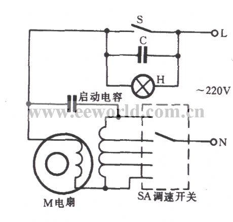
As shown in the circuit, capacitor C is generally used in 2.5 ~ 4.7μF/400V. Both ends of the C are connected with a switch S in parallel. When the S is closed, C is short and the fan operates according to the governor SA’s original gear operation. When S is turned off, the C is applied into the circuit in series. Due to its capacitance, the speed of fan motor M is reduced although governor SA’s gear operation is not changed. However, the wind speed is lower than the original one. H is a light of 8 ~ 10W. It can work as a light in a weak windshield, as well as providing a discharge path for capacitor C when the city power is cut.
(View)
View full Circuit Diagram | Comments | Reading(788)
bridge and pick-up type speaker protection circuit (b)
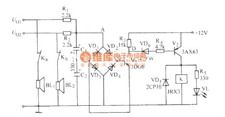
Published:2011/7/5 10:07:00 Author:John | Keyword: speaker
View full Circuit Diagram | Comments | Reading(2423)
bridge and pick-up type speaker protection circuit c
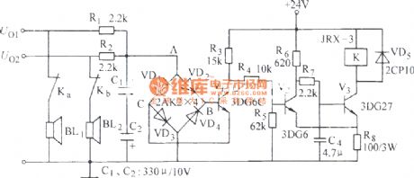
Published:2011/7/5 10:07:00 Author:John | Keyword: speaker
View full Circuit Diagram | Comments | Reading(2106)
Y-△ main circuit during the starting of thermal relay in Y
Published:2011/7/5 4:06:00 Author:John | Keyword: thermal relay
View full Circuit Diagram | Comments | Reading(728)
Gas stove safety valve control and language alarming circuit
Published:2011/7/5 3:56:00 Author:John | Keyword: Gas stove, safety valve
PDF for related components can be downloaded.
5559013SR8808The circuit is as shown. It consists of the gas sensor, one-shot trigger circuit, relay control motor circuits, voice circuit and communication buck rectifier circuit. When the gas concentration detected by the gas sensor exceeds a given concentration, the exhaust fan is automatically turned on and is issued whistles, thus being able to attract people’s attention and vigilance.
(View)
View full Circuit Diagram | Comments | Reading(1205)
Wound rotor type motor reverse brake circuit
Published:2011/7/5 3:51:00 Author:John | Keyword: Wound rotor, motor
View full Circuit Diagram | Comments | Reading(1754)
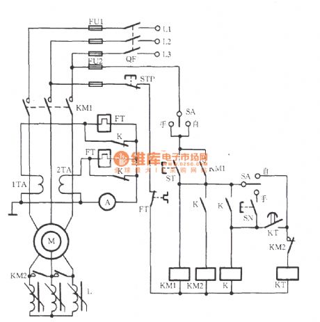
Wound rotor induction motor manual and automatic serial reactor step-down start-up circuit
Published:2011/7/5 3:50:00 Author:John | Keyword: serial reactor, Wound rotor, induction motor
View full Circuit Diagram | Comments | Reading(3076)
| Pages:224/312 At 20221222223224225226227228229230231232233234235236237238239240Under 20 |
Circuit Categories
power supply circuit
Amplifier Circuit
Basic Circuit
LED and Light Circuit
Sensor Circuit
Signal Processing
Electrical Equipment Circuit
Control Circuit
Remote Control Circuit
A/D-D/A Converter Circuit
Audio Circuit
Measuring and Test Circuit
Communication Circuit
Computer-Related Circuit
555 Circuit
Automotive Circuit
Repairing Circuit