
Control Circuit
Index 228
The touching switch circuit
Published:2011/7/3 21:20:00 Author:Borg | Keyword: touching switch
View full Circuit Diagram | Comments | Reading(683)
The touching interlock electric switch circuit
Published:2011/7/3 21:32:00 Author:Borg | Keyword: interlock, electric switch

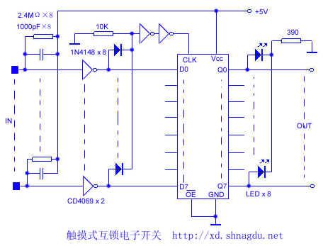
Usually, the RC of the phase inverter input terminal makes the output terminal 0, when touching the line i (i=0,1,2```7), the signal that is inducted by human body is sent to Di terminal and CLK terminal of 74LS374 respectively, at the moment, the CLK has the rising cause, so the state of D (except Di=1, others are 0) is locked on the Q terminal(Qi=Di=1), the corresponding LED is glowing; when the signal is gone(means no touch), the circuit is reset, so CLK has no rising cause.Therefore, only one line of lights are glowing when only one line is touched, which can fulfill the aim of interlocking and indication. (View)
View full Circuit Diagram | Comments | Reading(796)
The inductance controlled switch circuit (3)
Published:2011/7/2 23:08:00 Author:Borg | Keyword: inductance controlled, switch circuit
The circuit that will be introduced can be used to control the lighting lamp and auto door, and it can also be used to burglarproof alarm. This circuit consists of the inducting electrode plate A, regulated diode VS, FET transistor VF, music integrated circuit IC, transistor V, relay K, diode VD, resistor R1 and R2, potentiometer RP and power supply switch S, etc, see as the figure.
The inductance controlled switch circuit By adjusting the potentiometer RP, the music time of the IC can be changed, so the working time of the load can be changed. (View)
View full Circuit Diagram | Comments | Reading(669)
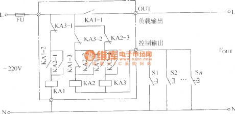
The switch circuit of electric self-lock/interlock
Published:2011/7/2 23:40:00 Author:Borg | Keyword: switch circuit, electric self-lock/interlock

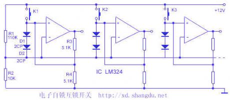
1.switch featuresThe core part of the switch is made of 4 op-amps LM324, with subtle design, each op-amp has two functions: the voltage comparator and the Schmidt trigger. The voltage range is large, and the stages can be adjusted, if it is added with a neutral gear, it can be the general reset, when the circuit cooperates with a digital circuit, they share a power supply, the input/output LEV conforms to the digital circuit connector LEV, as the input impedance of the op-amp is high, the input current of the switch is low. The touch switch, conductive rubber and film switch can be used as the key. (View)
View full Circuit Diagram | Comments | Reading(791)
High gear stepping dimmer controller circuit (1)
Published:2011/6/28 1:59:00 Author:Ecco | Keyword: High gear, stepping, dimmer, controller
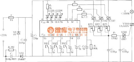
The chart shows the high gear stepping dimmer controller circuit, which has four gears to control stong, medium, weak, extinguish, and it also has four different timing blocks in 0.5h, 1h, 2h and 4h.
(View)
View full Circuit Diagram | Comments | Reading(587)
Motor protector 12
Published:2011/6/27 21:20:00 Author:Nicole | Keyword: Motor, protector
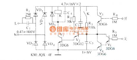
This motor protector circuit is composed of power supply circuit, voltage detection control circuit, it is shown in the figure 8-48.
The power supply circuit is made of power transformer T, rectifier diode VD3 and filter capacitor C3.
The voltage detection control circuit consists of potentiometer RP, diode VD1, VD2, capacitors C1, C2, steady voltage diode VS, resistor R, transistors V1, V2 and relay K.
In the motor control circuit, KM is the AC contactor , S1, S2 are the stop button and starter button.
(View)
View full Circuit Diagram | Comments | Reading(638)
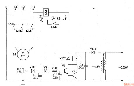
Motor protector 9
Published:2011/6/27 21:12:00 Author:Nicole | Keyword: Motor, protector
This motor protector circuit is composed of starting control circuit, phase failure detection circuit and protection implement circuit, it is shown in the figure 8-45.
The starting control circuit is made of starter button S2 and stop button S1.
The phase failure detection circuit consists of current mutual inductor TA, rectifier diode VD1, resistor R1, capacitor C and potentiometer RP1, RP.
The protection implement circuit is composed of transistors V1-V3, relay K and AC contactor KM.
V1's sensitivity can be changed by adjusting RP1 and RP2.
(View)
View full Circuit Diagram | Comments | Reading(1383)
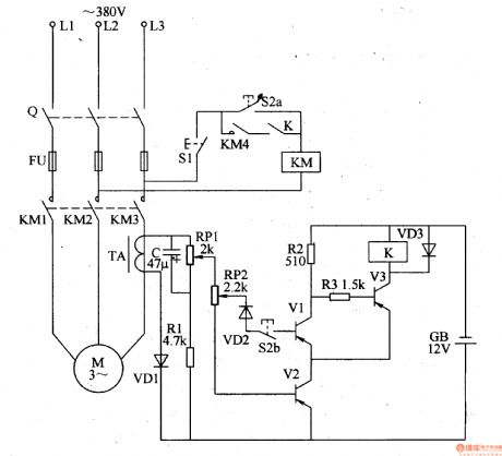
Motor protector 8
Published:2011/6/27 21:04:00 Author:Nicole | Keyword: Motor, protector
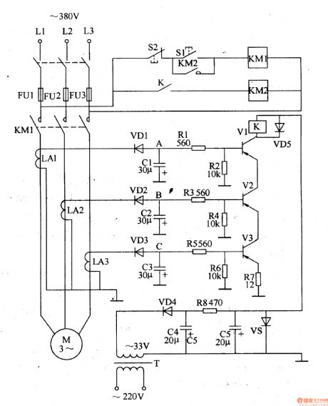
This motor protector circuit is composed of power supply circuit, current detection circuit and protection control circuit, it is shown in the figure 8-44.
The power supply circuit is made of power transformer C4, C5, current limiting resistor R8 and steady voltage diode VS, this circuit can produce +20V voltage, it feeds to relay K and the drive cirucit.
The current detection circuit consists of current converter LA1, LA2, LA3, rectifier diodes VD1-VD2, fliter capacitors C1-C3.
The protection control circuit is composed of resistors R1-R7, transistors V1-V3, relay K, AC contactor KM1, KM2, and starter button S1, stop button S2.
(View)
View full Circuit Diagram | Comments | Reading(644)
Motor protector 7
Published:2011/6/27 20:52:00 Author:Nicole | Keyword: Motor, protector
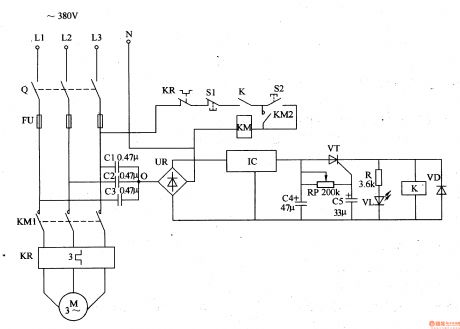
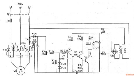
When the three-phase power supply is normal, the common contact 0 of detection capacitors C1-C3 has no current, the both sides of C4 has no voltage, thyristor VT is in off state, relay K does not pull in, the normally closed contact K is turned on, LED VL does not light, motor M works normally.
KP is heat relay, S1 is stop button, S2 is starter button, R is current limiting resistor.
The delay circuit is composed of potentiometer RP, capacitor C5 or thyristor VT, it can prevent protector from wrong actions due to serious harmonic interference or instantaneous voltage fluctuation.
(View)
View full Circuit Diagram | Comments | Reading(721)
Motor protector 5
Published:2011/6/27 5:18:00 Author:Nicole | Keyword: Motor, protector
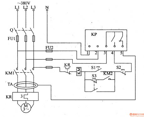
This motor protector circuit is composed of annular current transformer TA, protection relay KP, starter button S1, stop button S2, point button S3, AC contactor KM and heat relay KP, it is shown in the figure 8-41.
When stop button S2 is pressed, KM releases, M stops running.
When the motor M is leakage or the body touches the leakaged motor M, TA's current increases, KP does, it cuts off motor M's work power and self-locked.
When the motor M has over current or over load, heat relay KP does, KM is released, M stops running.
(View)
View full Circuit Diagram | Comments | Reading(937)
Motor protector 4
Published:2011/6/27 5:07:00 Author:Nicole | Keyword: Motor, protector
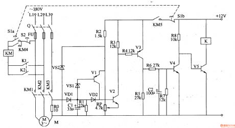
This motor protector circuit is composed of current detection control circuit and delay control circuit, it is shown in the figure 8-40.
The current detection control circuit is made of resistors R0-R5, transistors V1-V3, capacitor C1, diodes VD1, VD2 and Zener diode VS1, VS2.
The delay control circuit consists of resistors R6-R8, capacitor C2, transistors V4, V5 and relay K.
S1 is starter button, S2 is stop button, KM is AC contactor.
After S1 is pressed, V5 is saturation conduction, K pulls in, its normally open contacts K1, K2 are turned on, KM action makes motor M operated, at the same time, the current detection control circuit starts to work.
(View)
View full Circuit Diagram | Comments | Reading(599)
Motor protector 3
Published:2011/6/27 4:59:00 Author:Nicole | Keyword: Motor, protector
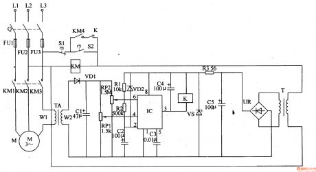
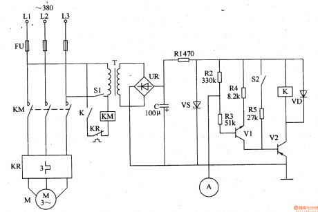
This motor protector circuit is composed of power supply circuit, current detection circuit and protection control circuit, it is shown in the figure 8-39.
The power supply circuit is made of power transformer T, bridge rectifier UR, fliter capacitors C5, current limiting resistor R3 and Zener diode VS.
The current detection circuit consists of current transformerTA, diode VD1, capacitor C1 and potentiometers RP1, RP2.
The protection control circuit is composed of time base integrated circuit IC, resistors R1, R2, diode VD2, capacitors C2-C4, relay K and AC contactor KM.
(View)
View full Circuit Diagram | Comments | Reading(1013)
Motor protector 2
Published:2011/6/27 4:53:00 Author:Nicole | Keyword: Motor, protector
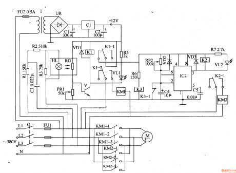
This motor protector circuit is composed of DC steady voltage power supply, phase sequence detection circuit, sampling control circuit and automatic converting circuit, it is shown in the figure 8-38.
The DC steady voltage power supply circuit is made of fuse FU2, power transformer T, bridge rectifier UR, fliter capacitors C1, C2 and there terminals steady voltage integrated circuit IC1.
The sampling control circuit consists of photosensitive resistor RG, potentiometer RP1, transistors R4, R6, R7, relay K1, diode VD1, resistor R5, LED VL1 and AC contactor KM1.
(View)
View full Circuit Diagram | Comments | Reading(651)
Loom saves electricity controller 3
Published:2011/6/29 21:41:00 Author:Nicole | Keyword: loom, saves electricity controller
The loom saves electricity controller circuit is composed of DC regulated power supply circuit, touch control circuit, automatically control circuit and master control circuit, it is shown in the figure 19.
The DC regulated power supply circuit is made of current transformer T, bridge rectifiers UR, filter capacitor C, current limiting resistor R1 and steady voltage diode VS.
The touch control circuit consists of touch electrode A, resistors R2-R4 and transistor V1.
The automatically control circuit is composed of travel switch S2, resistor R5, relay K, diode VD and transistor V2.
(View)
View full Circuit Diagram | Comments | Reading(1171)
Loom saves electricity controller 2
Published:2011/6/29 21:35:00 Author:Nicole | Keyword: loom, saves electricity controller
The loom saves electricity controller circuit is composed of 12V regulated power supply circuit, current detection amplifier circuit, relay control circuit and motor control switch circuit, it is shown in the figure 8-18.
The 12V regulated power supply circuit is made of current transformer T, bridge rectifiers UR, filter capacitors C4, C5, current limiting resistor R8 and steady voltage diode VS.
The current detection amplifier circuit consists of current transformer TA, diodes VDl-VD3, capacitor C1, potentiometer RP, resistors R1-R4, transistor V1.
V1-V3's sensitivity can be changed by adjusting RP.
(View)
View full Circuit Diagram | Comments | Reading(1072)
Loom saves electricity controller 1
Published:2011/6/29 21:20:00 Author:Nicole | Keyword: loom, saves electricity controller
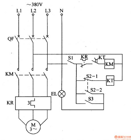
The loom saves electricity controller is composed of air switch QF, AC contactor KM, time relay KT, control switch S1, travel switch S2, hand brake indicator switch S3, heat relay KP and light EL, it is shown in the figure 8-17.
When the air switch QF is turned on, the loom's switch bar is pulled to start-up position, when the cam turns 5°-lO°, S2 is released, S2's normally closed contact S2-1 is turned on, time relay KT is turned on, the delay cutting normally open contact is connected, AC contactor KM pulls in, motor M starts working.
(View)
View full Circuit Diagram | Comments | Reading(1110)
DC switch circuit
Published:2011/7/3 19:06:00 Author:Christina | Keyword: DC, switch circuit
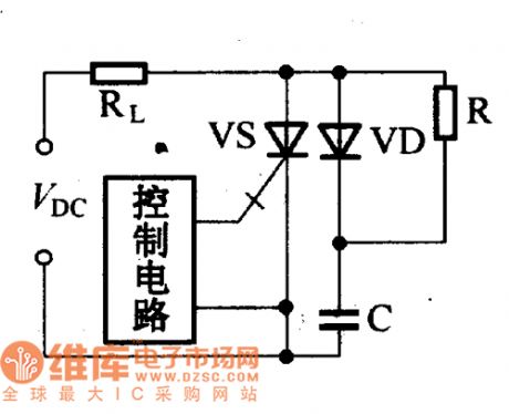
The DC switch circuit which is composed of the turn-off thyristor is as shown in the figure. The VD is the absorption diode, the C is the absorption capacitance, the R is the discharge resistance.
DC switch circuit (View)
View full Circuit Diagram | Comments | Reading(668)
The PWM realization circuit of the analog circuit
Published:2011/7/1 23:13:00 Author:Borg | Keyword: PWM, realization circuit, analog circuit
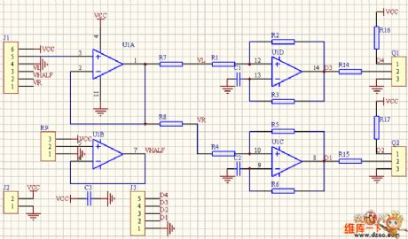
In the figure is the PWM generating circuit of the two chassises drive motor controlled by the linear circuit of game controller or the model airplane racker. J1 is the outlet of the racker, 123 and 456 are the potentiometer of the x and y dimension. U1B provide with the half power supply voltage, U1A is the voltage follower. The x and y become the voltage signal which controls the rotating speed of the left and right wheel after being compounded. While in use, we make L=(x+1)y/(x+1.4), R=(x-1)y/(x-0.6), and the effect proves to be good after the practice.
(View)
View full Circuit Diagram | Comments | Reading(701)
Automatic dimming curtain circuit
Published:2011/7/2 4:23:00 Author:John | Keyword: Automatic dimming curtain
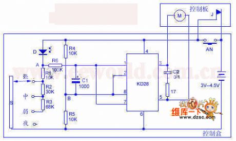
When the outdoor light enhances, the interior light also enhances and the photodiode resistance becomes smaller. Then the point A’s potential rises to drive the output potential to rise on KD28’s pin 3. Besides, the potential on pin 5 decreases to drive the motor M to transfer. Afterwards, the curtain slowly closes until the indoor light weakens. The resistance of D increases until it is large enough to drive the bridge to be balanced again. Conversely, when there is less light, the motor M rotates reversely to drive the curtain to slowly open. C1 and R6 operate with delay effect. This can make the control process undergo gradually, thus being able to avoid motor’s repeated starting because of the accidentally opened curtain from wind blowing.
(View)
View full Circuit Diagram | Comments | Reading(1792)
combustible gas automatic ignition device circuit
Published:2011/7/2 3:37:00 Author:John | Keyword: combustible gas, automatic ignition device
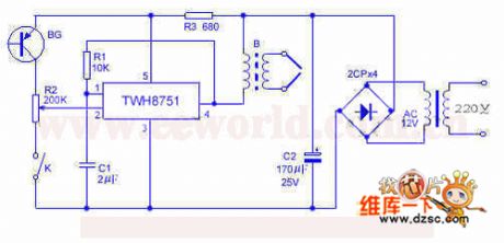
The device uses TWH8751 power electronic manifold to form a high voltage spark ignition device, which is made to be under the control of flame feedback optical signal. It also has the function to re-ignite after the turning off for some reason. If this device is compatible with other control circuit, the entire unit is able to achieve the automation of cooking. TWH8751, R1, C1 and others are used to constitute the square-wave generator. B2 is a booster, which can be the 12-inch ignition coil. Its primary stage uses 30 turns of 0.3mm enameled wire or output transformer in the tube radio with direct substitution.
(View)
View full Circuit Diagram | Comments | Reading(1218)
| Pages:228/312 At 20221222223224225226227228229230231232233234235236237238239240Under 20 |
Circuit Categories
power supply circuit
Amplifier Circuit
Basic Circuit
LED and Light Circuit
Sensor Circuit
Signal Processing
Electrical Equipment Circuit
Control Circuit
Remote Control Circuit
A/D-D/A Converter Circuit
Audio Circuit
Measuring and Test Circuit
Communication Circuit
Computer-Related Circuit
555 Circuit
Automotive Circuit
Repairing Circuit