
Control Circuit
Index 222
555 film showing automatic protection closing down circuit
Published:2011/6/12 22:30:00 Author:TaoXi | Keyword: 555, film showing, automatic protection, closing down
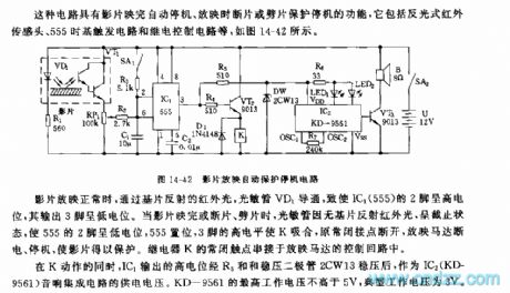
This kind of circuit is composed of the reflective type infrared sensor head, the 555 time-base trigger circuit and the relay control circuit.etc, as the figure 14-42 shows.
When the film is projecting, the infrared light which is reflected by the substrate conducts the photosensitive tube VD1 to make the pin-2 of IC1(555) to have the high electric potential, the output port pin-3 has the low electric potential. Then the film is over or interrupt, the photosensitive tube is in the cut-off state because of there is no reflection infrared ray, the 555's pin-2 has the low electric potential, the 555 sets, pin-3's high electrical level makes the K to close, the normally closed contact point cuts off, the screening motor has no power to work.
The normally closed contact point of relay K connects with the screening motor's control circuit.
(View)
View full Circuit Diagram | Comments | Reading(552)
The drainage and irrigation station remote controller circuit diagram
Published:2011/6/18 21:55:00 Author:Lucas | Keyword: drainage , irrigation , station , remote controller
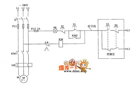
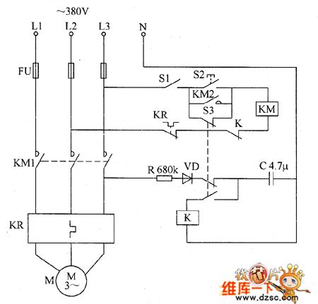
The drainage and irrigation station remote controller circuit consists of water pump motor M, knife switch Q, fuses FU1, FU2, AC contactor KM, thermal relay KR, control buttons S1 ~ S4, incandescent bulb HL and signal lines, and the circuit is shown as the Figure. Start button S3 and stop button S4 are installed in the control room to connect to the water pump motor circuit in drainage and irrigation station by the signal lines. It the farmland needs to stop the irrigation, people should press S4 to make the KM release because of two ends of coil being connected to L2-phase power, then the pump motor M stops.
(View)
View full Circuit Diagram | Comments | Reading(2094)
Agricultural submersible pump burglar alarm circuit diagram
Published:2011/6/12 22:55:00 Author:Lucas | Keyword: agricultural , submersible pump, burglar alarm
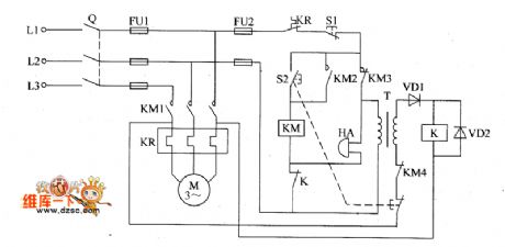
The agricultural submersible pump burglar alarm circuit is composed of the relay K, diodes VD1, VD2, power transformer T and bell HA, and the circuit is shown as the chart. When the submersible pump is stolen or disconnected because of other reasons, the power supply loop of relay K is cut off, and the normally closed contact is connected, then HA produces alarm sound. VD1 and VD2 use 1N5402 silicon rectifier diode or 2CP35B ordinary silicon diodes. HA chooses the alarm bell with working voltage being 380V. K selects JQX-4 24V DC relay. KM uses CDC10 380V AC contactor. T uses the power transformer with 3 ~ 5W, 25 ~ 30V secondary voltage(380V/25 ~ 30V). S1 selects moving off button; S2 selects portfolio button (each grous of moving on, moving off contacts). Fuse FU1, knife switch Q and the thermal relay KR should be selected according to the rated power of M; FU2 uses 2A fuse.
(View)
View full Circuit Diagram | Comments | Reading(2768)
Telephone line burglar alarm circuit diagram
Published:2011/6/30 5:36:00 Author:Lucas | Keyword: Telephone line, burglar alarm
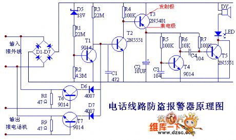
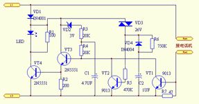
The breakover of T2 makes T3 breakover, and then the rear audio oscillation circuit, and LED, DY will emit aural and visual alarm, and it can add the interfere signal on out wire by LED, DY , while the voltage of out wire decreases, so those theft callers are forced to hang up as they can not dial. This alarm can monitor and prevent others from unauthorized using of your telephone line. When someone outside connects to your phone line and makes a free call, the alarm will issue the interference signals to forbid thieves from dialing, then it uses sound and light to inform of the owner somone having used the call.
(View)
View full Circuit Diagram | Comments | Reading(1393)
The loom electricity saving controller circuit diagarm 6
Published:2011/6/12 22:58:00 Author:Lucas | Keyword: loom , electricity saving controller
The loom electricity saving controller circuit is composed of the control switch S1, start button S2, AC contactor KM, thermal relay KR, relay K, resistor R, capacitor C, and the micro switch S3, and the circuit is shown as the chart. R uses 1W metal film resistor. C uses the oil condenser or CBB capacitor with the withstang voltage being 250V. VD uses 1N5406 silicon rectifier diode. S1 selects the 380V power switch with contact current being greater than 5A; S2 uses compression press making button; S3 selects limit switch. K selects JQX-10F 24V DC relay. KM selects the AC contact with the coil voltagein 380V, contact current capacityin 15A.
(View)
View full Circuit Diagram | Comments | Reading(703)
The gas limiting alarm miner lamp circuit diagram 4
Published:2011/7/4 22:05:00 Author:Lucas | Keyword: Gas limiting , alarm , miners lamp
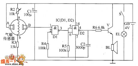
The gas limiting alarm miner lamp circuit is composed of the gas detection circuit, multivibrator, audio output circuit and the lighting circuit, and the circuit is shown as the chart. Gas detection circuit is composed of the gas sensor and resistors R2, R3. Multivibrator is composed of the two NAND gates D1, D2 which are inside of the NOT gate IC and resistors R4 and R5, capacitor C2. Audio output circuit consists of resistor R6, audio amplification tube V and speaker BL. Lighting circuit is composed of the battery GB, illuminating lamp EL and light switch S. R1 uses 1/2W carbon film resistor; R2 uses small sealed variable resistor; R3 ~ R6 select 1/4W carbon film resistors.
(View)
View full Circuit Diagram | Comments | Reading(833)
MC3423 overvoltage protection circuit, main features and pin of power monitor
Published:2011/7/4 22:34:00 Author:Lucas | Keyword: overvoltage , protection circuit, main features , pin , power monitor
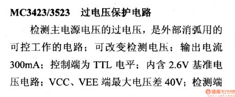
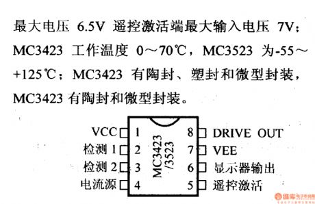
MC3423/3523 over-voltage protection circuitIt is a controllable circuit which is used for external arc extinction to detect over-voltage of main power supply voltage; it can change the detection voltage; output current is 300mA; control terminal is TTL level; it is embedded 2.6V voltage reference circuit; the maximum voltage difference between VCC and VEE ends is 40V; the maximum input voltage of detection end is 6.5V and the maximum input voltage of remote activation terminal is 7V; MC3423 operating temperature is 0 ~ 70 ℃, MC3523 is -55 ~ +125 ℃; MC3423 has the ceramic sealing, plastic and micro-encapsulation packages, MC3423 has the ceramic sealing and micro-encapsulation package.
(View)
View full Circuit Diagram | Comments | Reading(1062)
Robot control circuit composed of transistor and NE555
Published:2011/7/1 21:12:00 Author:Lucas | Keyword: Robot control , transistor
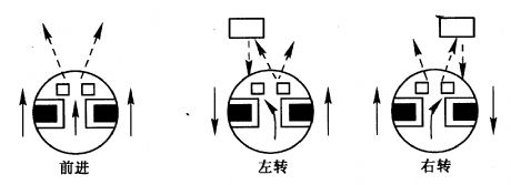
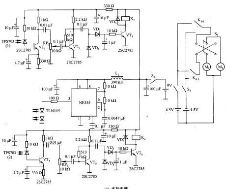
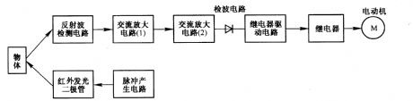
Figure 2-33 (a) is the action schematic diagram of the robot closing to the object. When there is no objects in front of the robot, it will go forward in the straight line; when there is an object in left or right side of the robot,it will turn left or right to close to the object. Figure 2-33 (b) is the block diagram to achieve this action. Figure 2-33 (c) is the actual circuit, in the circuit, NE555 is the multivibrator to produce pulse signal to modulate the infrared light emitted by infrared light-emitting diode TLNlO5, and the purpose is to avoid interference from other light. NE555 oscillation frequency is l0 kHz.
(View)
View full Circuit Diagram | Comments | Reading(2954)
Motor time division control circuit composed of transistor and NE555
Published:2011/6/30 21:06:00 Author:Lucas | Keyword: Motor , time division, control circuit , transistor
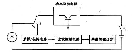

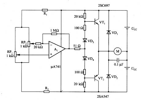
Figure 2-32 (a) shows the time control diagram, and the motor is operated by the switch S1. When Sl is turned to 1, the power driver circuit provides current to the motor for running; When S1 is turned to 2, the drive current is cut off, and the electric motor is used as a generator to hold out the back electromotive force by the sampling circuit. S1is turned to 2 by the sampling circuit, the back electromotive force is used as a sample to keep until the next on / off cycle of S1. Keeping the hold voltage and speed settings voltage be same can provide power for the motor control circuit.
(View)
View full Circuit Diagram | Comments | Reading(2620)
(Four-state) touching dimmer control circuit diagram
Published:2011/6/30 22:30:00 Author:Ecco | Keyword: Four-state , touching , dimmer control
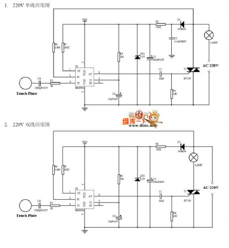
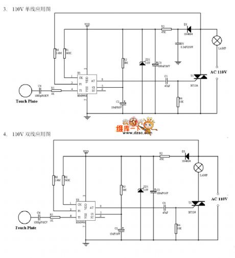
1. 220V mongline application diagram; 2.220V double-line application diagram; 3.110V mongline application diagram; 4. 110V dual-line application diagram
(View)
View full Circuit Diagram | Comments | Reading(1636)
MB3775 control circuit, main features and pin of DC-DC circuit and power supply monitor
Published:2011/6/28 5:44:00 Author:Lucas | Keyword: control circuit, main features , pin , DC-DC , power supply monitor
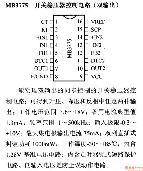
MB3775 switching regulator control circuit (dual output) It is the switching regulator control circuit which can achieve a dual-output synchronous control; it can output boost, buck in inverting way, and the working voltage range is 3.6 ~ 18V; the spare typical current is 1.3mA; frequency range is 1 ~ 500kHz; input limit is -0.3 ~ +10 V; maximum collector output current is 75mA; dual in-line package power is 1000mW; Operating Temperature is -30 ~ +85 ℃; it contains 1.28V reference voltage circuit; it includes timer locking short protection circuit to prevent malfunction circuit from the low input voltage.
(View)
View full Circuit Diagram | Comments | Reading(817)
MB3778 control circuit, main features and pin of DC-DC circuit and power supply monitor
Published:2011/6/22 6:48:00 Author:Lucas | Keyword: control circuit, main features , pin , DC-DC circuit , power supply monitor
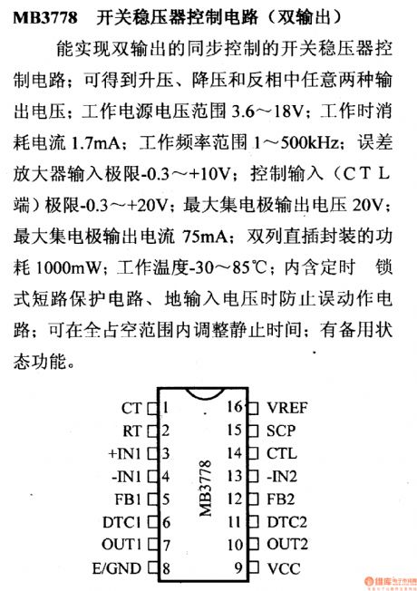
MB3778 switching regulator control circuit (dual output) The working supply voltage range is 3.6 ~ 18V; Current consumption is 1.7mA; frequency range is 1 ~ 500 KHZ; error amplifier input limit is -0.3 ~ +10 V; control input (CTL end) limit is -0.3 ~ +20 V; Collector output voltage is 20V; maximum collector output current is 75mA; power cost of dual in-line package is 1000mW; Operating Temperature is -30 ~ 85 ℃; the circuit includes timing, lock short-circuit protection circuit, input voltage malfunction prevention circuit; and it can adjust the rest time in the scope of the whole duty; it has the standby function.
(View)
View full Circuit Diagram | Comments | Reading(626)
MC3420 control circuit, main features and pin of DC-DC circuit and power supply monitor
Published:2011/6/30 20:13:00 Author:Lucas | Keyword: control circuit, main features , pin , DC-DC , power supply monitor
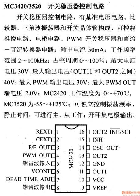
MC3420/3520 switching regulator control circuit The circuit is composed of reference voltage circuit, comparator, triangle wave oscillator and switching transistor, which may constitute a push-pull circuit, bridge circuit, PWM switching regulator and DC - DC converter circuit; output current is 50mA; frequency range is 2 ~ 100KHZ; duty cycle is 0 to 100%; maximum supply voltage is 30V; maximum output voltage (OUT11 and between OUT2) is 40V; maximum PWM output voltage is 30V; maximum PWM OUT voltage is 2.0V; MC2420 operating temperature is 0 ~ +70 ℃, MC3520 is -55 ~ +125 ℃.
(View)
View full Circuit Diagram | Comments | Reading(655)
The remote control lock alarm(TH151A/B, the vibration sensor T968)
Published:2011/7/4 20:31:00 Author:Borg | Keyword: remote control, lock alarm
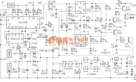
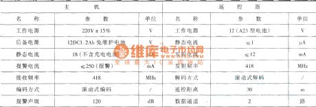
This circuit consists of the burglarproof host, door magnet trigger switch, vibration sensing switch, electric control lock with keys, battery that doesn't need maintenance and AC power supply, etc.Hose circuit:
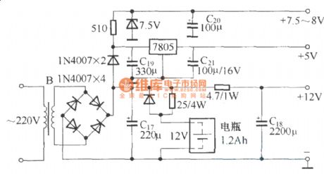
Power supply circuit:
The working parameters of the hose and remote control:
(View)
View full Circuit Diagram | Comments | Reading(813)
The invade break-down caller circuit of the balcony door/window
Published:2011/7/4 20:52:00 Author:Borg | Keyword: invade, caller, balcony door/window
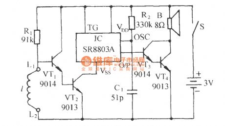
See as the figure, the circuit consists of the electric switch and language sound generating circuit, two parts in total. When the alarm line 1 of the balcony is broken down by the invader, it will generate the hurried calling sound immediately. (View)
View full Circuit Diagram | Comments | Reading(766)
The small and contactless fridge time delay protector circuit
Published:2011/7/4 21:05:00 Author:Borg | Keyword: contactless fridge, time delay protector
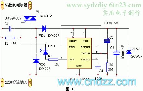
The small and contactless fridge time delay protector The contactless fridge has a few elements, and it's low-cost, small-size and without debugging, of which the dual-way SCR replaces the relay.Working principle The protector circuit is shown in the figure. The 220V AC current is stepped down by capacitor C1, half-rectified by VD1, regulated by VDW, and then sent to the time-based circuit 555 as the working power supply, the time of getting through is 5 min, the output terminal of 3-pin of the time-based circuit is shifted from low LEV to high LEV, the dual-way SCR VS is conducting and getting into work, which powers the fridge. At the moment, the LED is glowing, which means the power supply is normal.
(View)
View full Circuit Diagram | Comments | Reading(1423)
The mains voltage dual-way crossing lime alarm circuit
Published:2011/7/4 21:41:00 Author:Borg | Keyword: mains voltage, dual-way, alarm circuit
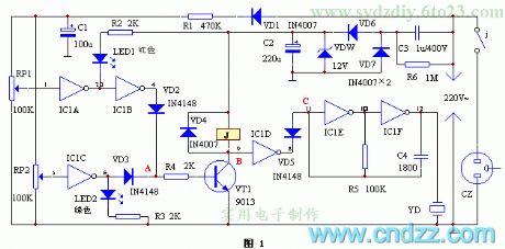
See as Figure 1, one line of the mains voltage is stepped down by C3, stabilized by DW, rectified by VD6, VD7 and C2, and then a 12V stable DC voltage is delivered to the circuit. The other line is rectified by VD1, stepped down by R1, filtered by C1 and then a 10.5v voltage that is detecting the mains input signal change on RP1 and RP2. The gates of IC1A and IC1B compose the over-voltage circuit, IC1C is the low-voltage detector, IC1D is the switch, IC1F, IC1E and the voltage pottery YD and so on compose the audio pulse oscillator. The triode VT, relay J and so on compose the protection circuit. (View)
View full Circuit Diagram | Comments | Reading(645)
The practical phone burglarproof alarm circuit
Published:2011/7/5 8:09:00 Author:Borg | Keyword: burglarproof alarm
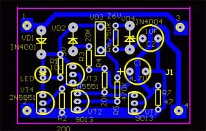
The circuit principleThe practical phone burglarproof alarm circuit is shown as above.
When the external wire of the phone is normal, there is a 48~60v DC voltage in the line, which triggers the dual-way triggering diode DV3 conducting by VD1, so the triode VT2 is saturated and conducting. Both VT3 and VT4 are blocked without the bias voltage on the basic pole, the LED is not glowing and alarming. When the external wire is used by others, the voltage is dropping to 10V or so, the dual-way triggering transistor VD3 is broken down. (View)
View full Circuit Diagram | Comments | Reading(647)
The auto alarm of money box or secret room being pried
Published:2011/7/4 21:47:00 Author:Borg | Keyword: auto alarm, money box
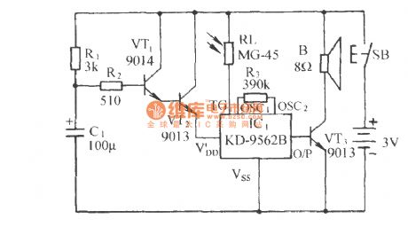
See as the figure, the circuit includes the box-door linked switch SB, electric switch, light control sound circuit and audio amplifier circuit, etc. Put the circuit in the closed secret chamber or money box, when it is pried, the circuit will make alarm sound of Ooo```Ooo``` (View)
View full Circuit Diagram | Comments | Reading(2053)
The vehicle or room timer alarm circuit
Published:2011/7/4 22:09:00 Author:Borg | Keyword: timer alarm
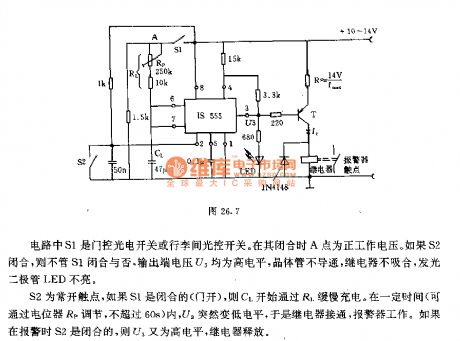
In the circuit, S1 is the door control photoelectric switch or the trunk light control switch. When it is pulling, the point A is the forward working voltage. If S2 is closed, whether S1 is closed or not, the voltage U3 on the output terminal will be a high LEV, the transistor is blocked, the relay is no pulling in, the LED is not glowing. S2 is the normally open contacator, if S1 is closed(the door is open), C1 will be charged by R1. In certain time(which can be adjusted by the potentiometer Rp), U3 is suddenly changed into the low LEV, so the relay is on and the alarm is working. (View)
View full Circuit Diagram | Comments | Reading(683)
| Pages:222/312 At 20221222223224225226227228229230231232233234235236237238239240Under 20 |
Circuit Categories
power supply circuit
Amplifier Circuit
Basic Circuit
LED and Light Circuit
Sensor Circuit
Signal Processing
Electrical Equipment Circuit
Control Circuit
Remote Control Circuit
A/D-D/A Converter Circuit
Audio Circuit
Measuring and Test Circuit
Communication Circuit
Computer-Related Circuit
555 Circuit
Automotive Circuit
Repairing Circuit