
Control Circuit
Index 223
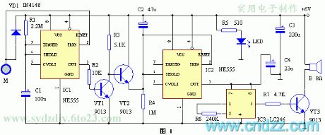
The gas putting out alarm circuit of auto start
Published:2011/7/4 22:38:00 Author:Borg | Keyword: putting out alarm, auto start
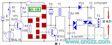
The principle circuit is shown in figure 1. The switch S is linked with the gas switch. When the gas valve is open, S is closed, if the gas is not lit, the LDR R2 is in a high LEV, the triode VT1 is conducting, which triggers the music integrated circuit to play music. At the same time, the transformer T1 is stepping up and outputting a pulse voltage with the peak value of 120Vpp, C1 is charged by R5 and C2 is charged by VD1. When C1 gets a certain voltage, the trigger VD2 is conducting, so is SCR, which makes the charged C2 discharges through T2 primary stage and SCR. (View)
View full Circuit Diagram | Comments | Reading(643)
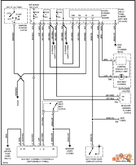
BENZ-560SEL automatic locking differential circuit
Published:2011/7/5 19:02:00 Author:Christina | Keyword: automatic locking, differential circuit
View full Circuit Diagram | Comments | Reading(574)
The lighting early warning device circuit
Published:2011/7/4 21:18:00 Author:Borg | Keyword: lighting, early warning device
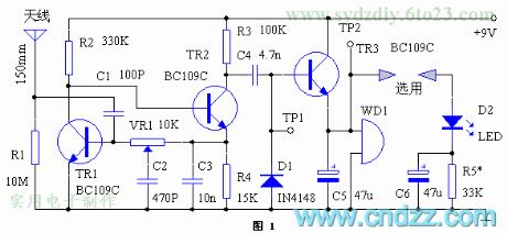
Working principle
The working principle is shown in figure 1, the feature of the circuit is that it can be adjusted to the self-oscillating state. The bias resistor in the figure can acquire the best relaxation feature. The oscillator is DC coupled, and the feedback branch is the collecting electrode of TR1 and the basic pole of TR2. The total gain of the circuit is set by the multi-turn (11,18 and 20) preset potentiometer VR1.The capacitor C3 sets the solid LEV of the TR2 emitting pole, and the capacitor C2 on VR1 smooth contactor is increasing the phase movement when it is oscillating.
(View)
View full Circuit Diagram | Comments | Reading(710)
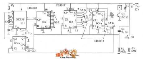
The watchdog circuit
Published:2011/7/5 8:21:00 Author:Borg | Keyword: watchdog circuit
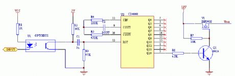
See as the figure: when the circuit is working, just a CD4060 reset pulse is delivered timely, Q1 will be sure to be blocked, so the NMOS tube under control is conducting and provides power for the circuit.
The virtue of the circuit is that the time is long, up to several minutes, which allows some systems to take a long time to reset. When the watchdog is fed with the pulse, a reset pulse is delivered to the auto counter by R2, C1 and R3, which makes sure Vout has output. (View)
View full Circuit Diagram | Comments | Reading(2137)
The frequency converter circuit with a main speed setting box and linked set operational box
Published:2011/7/5 20:23:00 Author:Borg | Keyword: frequency converter, operational box
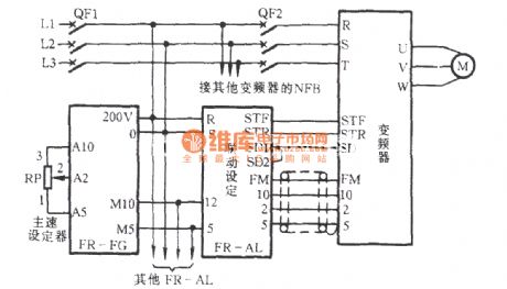
In the figure, FR-FG is the main speed setting part, FR-AL is the linked set operational box. In the circuit is the NFB which can connect with more than on FR-AL linked setting boxes and frequency converter, it can make several 3-phase motor run synchronously, and it is also use to synchronous acceleration/deceleration (speed regulation). The main speed regulation is done by the potentiometer RP. (View)
View full Circuit Diagram | Comments | Reading(1039)
Multi-function adjustable general time relay circuit
Published:2011/7/5 20:27:00 Author:Christina | Keyword: Multi-function, adjustable, general time, relay circuit
The multi-function of this circuit means that it has three kinds of operating modes: the delay closing , the delay releasing and the delay circulating . The delay closing means that after this relay is set, the relay will not close. Only when the preset time is up, the relay will close. The delay releasing is opposite withe the delay closing , the relay will close after the pre-boot, when the preset time is up, the relay will release. The delay closing and the delay releasing are disposable.
(View)
View full Circuit Diagram | Comments | Reading(984)
The alarm lamp circuit of reliable indicators
Published:2011/7/5 8:34:00 Author:Borg | Keyword: alarm lamp, reliable indicators
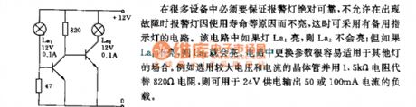
In many devices, there must be the reliable alarm lamps, and it does not allow the indicator to be cut off when the machine is malfunctioning, so the circuit with device indicator can be adopted.in the circuit, if La1 is lighting, La2 won't be light, and vice versa. The parameters of the circuit can easily be changed, so the circuit can be used in other situations. For example, to replace the 820Ω resistor by a transistor of large voltage and current with a 1.5kΩ, which can be used in the 50 or 100mA current load powered by the 24V voltage. (View)
View full Circuit Diagram | Comments | Reading(622)
The door lock alarm with the time recognition function
Published:2011/7/5 8:46:00 Author:Borg | Keyword: door lock alarm, time recognition
The circuit is shown in figure 1, which is composed of the 555 time-based integrated circuit and alarm integrated circuit. The time-based circuit IC1 consists of the temporary single steady trigger of T=4min or so with R1 and C1. Usually, IC1 is in the stable state, and the 3-pin of it outputs a low LEV, VT1 is blocked, VT2 is conducting, the capacitor C2 is shortened by VT2 and can't be charged, the 6-pin on the threshold of the time-based circuit IC2 is in a high LEV, while 3-pin is outputting a low LEV, the alarm sound integrated circuit IC3 is not working without power, the loudspeaker is silent. M is the touching electrode chip which is linked to the lock. (View)
View full Circuit Diagram | Comments | Reading(655)
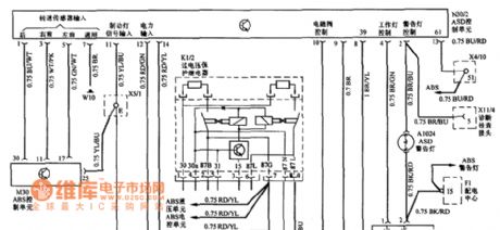
Volkswagen alarm system circuit
Published:2011/7/5 20:06:00 Author:Christina | Keyword: Volkswagen, alarm system
View full Circuit Diagram | Comments | Reading(861)
The transistor and gate protection circuit
Published:2011/7/4 22:43:00 Author:Borg | Keyword: transistor, protection
View full Circuit Diagram | Comments | Reading(751)
The frequency converter speed circuit with a ratio setting case
Published:2011/7/5 6:18:00 Author:Borg | Keyword: frequency converter, speed circuit
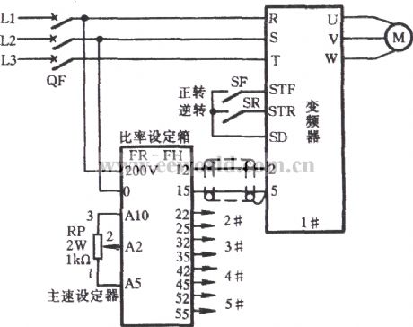
See as the figure, FR—FH is the ratio setting case, which can connect with 5 frequency converters. When more than one frequency converters need to output the ratios that are different from the main control speed, the FR-FH can set this, for example, during the progress of assembly line delivery, there are speed differences among the processes while the main speed is changeable, the connection can be done according to the figure. (View)
View full Circuit Diagram | Comments | Reading(604)
The frequency converter speed circuit with a link setting case
Published:2011/7/5 6:26:00 Author:Borg | Keyword: frequency converter, speed circuit
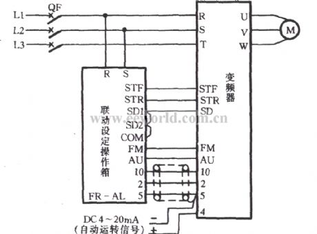
FR—AL is a link setting case. When the external is used to control the link of the frequency converter, the circuit shown in the figure can be adopted. In the figure, the 4-pin and 5-pin of the converter import a running signal of a 4~20mA DC, by which the rotating speed of motor M is controlled. The 4~20mA DC signal may be from the auto instrument, such as the speed sensor, mechanical sensor and so on. (View)
View full Circuit Diagram | Comments | Reading(557)
The frequency converter speed circuit with a triple speeds setting case
Published:2011/7/5 6:36:00 Author:Borg | Keyword: frequency converter, speed circuit
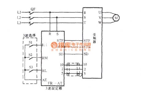
FR—AT is a triple speed setting case. When the motor M is running, different speeds are often needed at some moment, such as polishing, stirring, dehydrating, centrifuging, grinding and washing equipment and others, they often need multi-stage speeds in the processes, at this moment, the circuit in the figure can be chosen. The triple speeds selection can be done by the manual switches of S1, S2 and S3. The wire that links FR-AT to the frequency converter should be the insulated. (View)
View full Circuit Diagram | Comments | Reading(616)
The speed circuit of the frequency converter with a pre-amplifier box
Published:2011/7/5 10:04:00 Author:Borg | Keyword: frequency converter, pre-amplifier box
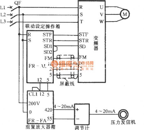
The frequency converter is a new style speed device which came out in recent years. With external units, the converter can expand its functions, so it can meet the technical and practical need. In the circuit fixes a unit of MI converter, i.e the circuit in which the figured FR operation box, setting box, preamplifier box and so on are linked with the converter, and the circuit controls the running of the 3-phase motor. The preamplifier box(FR-FA) can be the current/voltage signal converter or the computing amplifier. (View)
View full Circuit Diagram | Comments | Reading(721)
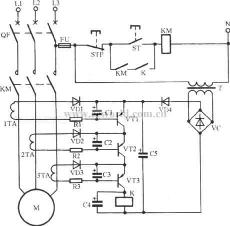
The operation circuit with the release relay
Published:2011/7/5 10:19:00 Author:Borg | Keyword: operation circuit, release relay
In some departments that need continuous work and can't be powerless, when the grid is power-off, they get the additional diesel generators into use immediately, which need the motor to start quickly. In the figure is the OFF-ON circuit which is fitted in these situations. When the key ST is pressed, the AC contactor KM is closed, the middle relay K and the time relay KT are closing in turn, the motor is working. If the gird is broken down, K will release power immediately, the coil of KT is (the release relay) power-off. (View)
View full Circuit Diagram | Comments | Reading(717)
The frequency converter circuit with a track setting box
Published:2011/7/5 20:02:00 Author:Borg | Keyword: frequency converter, track setting box
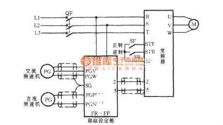
FR-FP is the track setting box (module). When a motor needs to track the rotating speed of another motor, the speed detector with a FR-FP can fulfill this forward/backward speed track control. Of the AC speed detector and DC speed detector, only can be chosen.
(View)
View full Circuit Diagram | Comments | Reading(642)
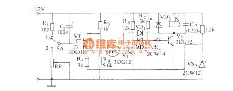
The insulated grid FET long time delay circuit (1)
Published:2011/7/5 10:21:00 Author:Borg | Keyword: insulated grid, FET
View full Circuit Diagram | Comments | Reading(579)
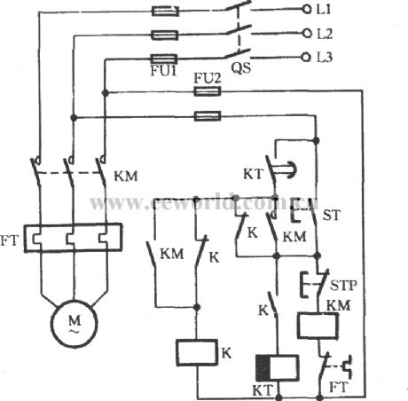
The interval operational circuit of starting time delay
Published:2011/7/5 20:12:00 Author:Borg | Keyword: operational circuit, time delay
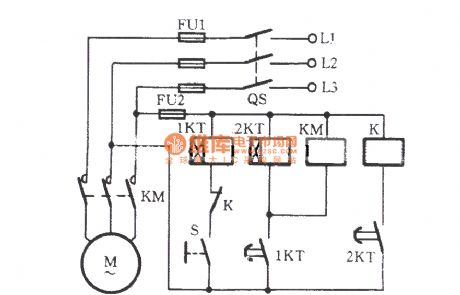
Working process: the power supply switch of QS is closed first, then the hand switch S is closed. At this moment, M is not starting immediately, but the relay 1KT is getting power and the timing is starting, when it is the regulated time of 1KT, its delaying contactor is closing, when the time relay coil of 2KT gets power and is starting to time, the coil of the AC contactor KM is getting power, the main contactor of KM is taking action, M is starting. After some time, the contactor of 2KT is taking action, the relay K is pulling in, and the normally open contactor is cut off. (View)
View full Circuit Diagram | Comments | Reading(655)
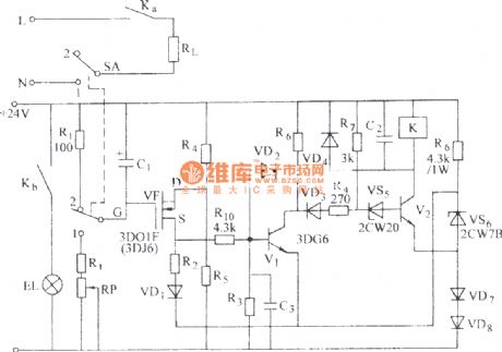
The insulated grid FET long time delay circuit (2)
Published:2011/7/5 10:22:00 Author:Borg | Keyword: insulated, grid FET
View full Circuit Diagram | Comments | Reading(560)
the circuit for preventing outdoor people from press the button in chaos
Published:2011/7/5 11:08:00 Author:John | Keyword: outdoor people, button
The circuit shown in the figure is for electric control systems of lifting loading and unloading machinery. It is reversible to run two motors. During the operating process, the circuit breaker QF is connected. Hold down the selected button on the left hand (for example, ST2). Thus, the corresponding AC contactor suctions. Afterwards, the starting button ST1 is turned on with the right hand. Besides, these two buttons are pressed to start the motor. The outsiders do not know that the motor can not be turned up only by conventional press on the button with one hand.
(View)
View full Circuit Diagram | Comments | Reading(648)
| Pages:223/312 At 20221222223224225226227228229230231232233234235236237238239240Under 20 |
Circuit Categories
power supply circuit
Amplifier Circuit
Basic Circuit
LED and Light Circuit
Sensor Circuit
Signal Processing
Electrical Equipment Circuit
Control Circuit
Remote Control Circuit
A/D-D/A Converter Circuit
Audio Circuit
Measuring and Test Circuit
Communication Circuit
Computer-Related Circuit
555 Circuit
Automotive Circuit
Repairing Circuit